How do 3d printers work video
3D Printing: What It Is, How It Works and Examples
3D printers might seem like they're right out of a science fiction movie, but they're proving to be useful in a variety of industries. | Image: ShutterstockHow Do 3D Printers Work?
3D printing is part of the additive manufacturing family and uses similar methods to a traditional inkjet printer — albeit in 3D. Additive manufacturing describes the process of creating something in layers, adding material continuously until the final design is complete. This term most often refers to molding and 3D printing.
It takes a combination of top-of-the-line software, powder-like materials and precision tools to create a three-dimensional object from scratch. Below are a few of the main steps 3D printers take to bring ideas to life.
How Does a 3D Printer Work?
3D printers are related to additive manufacturing. 3D printers use computer-aided design to understand a design. When a design is ready, a material that can be dispensed through a hot nozzle or precision tool is printed layer by layer to create a three-dimensional object from scratch.
3D Modeling Software
The first step of any 3D printing process is 3D modeling. To maximize precision — and because 3D printers can’t magically guess what you want to print — all objects have to be designed in a 3D modeling software. Some designs are too intricate and detailed for traditional manufacturing methods. That’s where CAD software comes in.
Modeling allows printers to customize their product down to the tiniest detail. The 3D modeling software’s ability to allow for precision designs is why 3D printing is being hailed as a true game changer in many industries. This modeling software is especially important to an industry, like dentistry, where labs are using 3D software to design teeth aligners that precisely fit to the individual. It’s also vital to the space industry, where they use the software to design some of the most intricate parts of a rocketship.
3D PRINTERS USE MODELING AND SLICING SOFTWARE TO GUIDE THE PRINTER IN CREATING EACH OBJECT. Video: Digital Trends
Slicing the Model
Once a model is created, it’s time to “slice” it. Since 3D printers cannot conceptualize the concept of three dimensions, like humans, engineers need to slice the model into layers in order for the printer to create the final product.
Slicing software takes scans of each layer of a model and will tell the printer how to move in order to recreate that layer. Slicers also tell 3D printers where to “fill” a model. This fill gives a 3D printed object internal lattices and columns that help shape and strengthen the object. Once the model is sliced, it’s sent off to the 3D printer for the actual printing process.
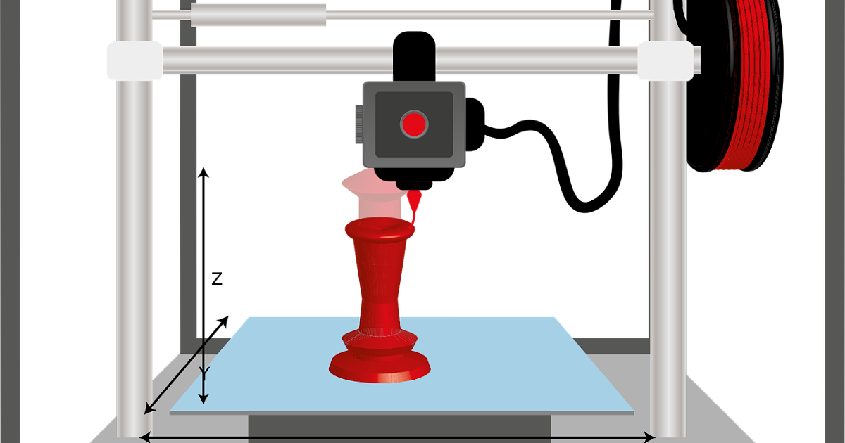
The 3D Printing Process
When the modeling and slicing of a 3D object is completed, it’s time for the 3D printer to finally take over. The printer acts generally the same as a traditional inkjet printer in the direct 3D printing process, where a nozzle moves back and forth while dispensing a wax or plastic-like polymer layer-by-layer, waiting for that layer to dry, then adding the next level. It essentially adds hundreds or thousands of 2D prints on top of one another to make a three-dimensional object.
3D Printing Materials
There are a variety of different materials that a printer uses in order to recreate an object to the best of its abilities. Here are some examples:
Acrylonitrile Butadiene Styrene (ABS)
Plastic material that is easy to shape and tough to break. The same material that LEGOs are made out of.
Carbon Fiber Filaments
Carbon fiber is used to create objects that need to be strong, but also extremely lightweight.
Conductive Filaments
These printable materials are still in the experimental stage and can be used for printing electric circuits without the need for wires. This is a useful material for wearable technology.
Flexible Filaments
Flexible filaments produce prints that are bendable, yet tough. These materials can be used to print anything from wristwatches to phone covers.
Metal Filament
Metal filaments are made of finely ground metals and polymer glue. They can come in steel, brass, bronze and copper in order to get the true look and feel of a metal object.
Wood Filament
These filaments contain finely ground wood powder mixed with polymer glue. These are obviously used to print wooden-looking objects and can look like a lighter or darker wood depending on the temperature of the printer.
The 3D printing process takes anywhere from a few hours for really simple prints, like a box or a ball, to days or weeks for much larger detailed projects, like a full-sized home.
How Much Do 3D Printers Cost?
The cost of 3D printers vary based on the size, specialty and use. The cheapest 3D printers, for entry level hobbyists, typically range from $100 to $500. More advanced models can range between $300 and $5,000. Industrial 3D printers can cost up to $100,000.
3D Printing Processes and Techniques
here are also different types of 3D printers depending on the size, detail and scope of a project. Each different type of printer will vary slightly on how an object gets printed.
Fused Deposition Modeling (FDM)
FDM is probably the most widely used form of 3D printing. It’s incredibly useful for manufacturing prototypes and models with plastic.
Stereolithography (SLA) Technology
SLA is a fast prototyping printing type that is best suited for printing in intricate detail. The printer uses an ultraviolet laser to craft the objects within hours.
Digital Light Processing (DLP)
DLP is one of the oldest forms of 3D printing. DLP uses lamps to produce prints at higher speeds than SLA printing because the layers dry in seconds.
Continuous Liquid Interface Production (CLIP)
CLIP is amongst the faster processes that use Vat Photopolymerisation. The CLIP process utilizes Digital Light Synthesis technology to project a sequence of UV images across a cross-section of a 3D printed part, resulting in a precisely controlled curing process. The part is then baked in a thermal bath or oven, causing several chemical reactions that allow the part to harden.
Material Jetting
Material Jetting applies droplets of material through a small diameter nozzle layer-by-layer to build a platform, which becomes hardened by UV light.
Binder Jetting
Binder Jetting utilizes a powder base material layered evenly along with a liquid binder, which is applied through jet nozzles to act as an adhesive for the powder particles.
Fused Deposition Modeling (FDM)
FDM, also known as Fused Filament Fabrication (FFF), works by unwinding a plastic filament from a spool and flowing through a heated nozzle in horizontal and vertical directions, forming the object immediately as the melted material hardens.
Selective Laser Sintering (SLS)
A form of Powder Bed Fusion, SLS fuses small particles of powder together by use of a high-power laser to create a three-dimensional shape. The laser scans each layer on a powder bed and selectively fuses them, then lowering the powder bed by one thickness and repeating the process through completion.
Multi-Jet Fusion (MJF)
Another form of Powder Bed Fusion, MJF uses a sweeping arm to deposit powder and an inkjet-equipped arm to apply binder selectively on top. Next, a detailing agent is applied around the detailing agent for precision. Finally, thermal energy is applied to cause a chemical reaction. Direct Metal Laser Sintering (DMLS) also utilizes this same process but with metal powder specifically.
Sheet Lamination
Sheet Lamination binds material in sheets through external force and welds them together through layered ultrasonic welding. The sheets are then milled in a CNC machine to form the object’s shape.
Directed Energy Deposition
Directed Energy Deposition is common in the metal industry and operates by a 3D printing apparatus attached to a multi-axis robotic arm with a nozzle for applying metal powder. The powder is applied to a surface and energy source, which then melts the material to form a solid object.
What is 3D printing? How does a 3D printer work? Learn 3D printing
3D printing or additive manufacturing is a process of making three dimensional solid objects from a digital file.
The creation of a 3D printed object is achieved using additive processes. In an additive process an object is created by laying down successive layers of material until the object is created. Each of these layers can be seen as a thinly sliced cross-section of the object.
3D printing is the opposite of subtractive manufacturing which is cutting out / hollowing out a piece of metal or plastic with for instance a milling machine.
3D printing enables you to produce complex shapes using less material than traditional manufacturing methods.
Table of Contents
- How Does 3D Printing Work?
- 3D Printing Industry
- Examples of 3D Printing
- 3D Printing Technologies & Processes
- Materials
- Services
Jump to your field of interest:
- Rapid Prototyping & Manufacturing
- Automotive
- Aviation
- Construction
- Consumer Products
- Healthcare
- Food
- Education
Jump to process:
- All Technologies & Processes
- Vat Photopolymerisation
- Material Jetting
- Binder Jetting
- Material Extrusion
- Powder Bed Fusion
- Sheet Lamination
- Directed Energy Deposition
How Does 3D Printing Work?
It all starts with a 3D model. You can opt to create one from the ground up or download it from a 3D library.
3D Software
There are many different software tools available. From industrial grade to open source. We’ve created an overview on our 3D software page.
We often recommend beginners to start with Tinkercad. Tinkercad is free and works in your browser, you don’t have to install it on your computer. Tinkercad offers beginner lessons and has a built-in feature to export your model as a printable file e.g .STL or .OBJ.
Now that you have a printable file, the next step is to prepare it for your 3D printer. This is called slicing.
Slicing: From printable file to 3D Printer
Slicing basically means slicing up a 3D model into hundreds or thousands of layers and is done with slicing software.
When your file is sliced, it’s ready for your 3D printer. Feeding the file to your printer can be done via USB, SD or Wi-Fi. Your sliced file is now ready to be 3D printed layer by layer.
3D Printing Industry
Adoption of 3D printing has reached critical mass as those who have yet to integrate additive manufacturing somewhere in their supply chain are now part of an ever-shrinking minority. Where 3D printing was only suitable for prototyping and one-off manufacturing in the early stages, it is now rapidly transforming into a production technology.
Most of the current demand for 3D printing is industrial in nature. Acumen Research and Consulting forecasts the global 3D printing market to reach $41 billion by 2026.
As it evolves, 3D printing technology is destined to transform almost every major industry and change the way we live, work, and play in the future.
Examples of 3D Printing
3D printing encompasses many forms of technologies and materials as 3D printing is being used in almost all industries you could think of. It’s important to see it as a cluster of diverse industries with a myriad of different applications.
A few examples:
- – consumer products (eyewear, footwear, design, furniture)
- – industrial products (manufacturing tools, prototypes, functional end-use parts)
- – dental products
- – prosthetics
- – architectural scale models & maquettes
- – reconstructing fossils
- – replicating ancient artefacts
- – reconstructing evidence in forensic pathology
- – movie props
Rapid Prototyping & Rapid Manufacturing
Companies have used 3D printers in their design process to create prototypes since the late seventies. Using 3D printers for these purposes is called rapid prototyping.
Why use 3D Printers for Rapid Prototyping?
In short: it’s fast and relatively cheap. From idea, to 3D model to holding a prototype in your hands is a matter of days instead of weeks. Iterations are easier and cheaper to make and you don’t need expensive molds or tools.
Besides rapid prototyping, 3D printing is also used for rapid manufacturing. Rapid manufacturing is a new method of manufacturing where businesses use 3D printers for short run / small batch custom manufacturing.
Automotive
Car manufacturers have been utilizing 3D printing for a long time. Automotive companies are printing spare parts, tools, jigs and fixtures but also end-use parts. 3D printing has enabled on-demand manufacturing which has lead to lower stock levels and has shortened design and production cycles.
Automotive enthusiasts all over the world are using 3D printed parts to restore old cars. One such example is when Australian engineers printed parts to bring a Delage Type-C back to life. In doing so, they had to print parts that were out of production for decades.
Aviation
Aviation loves additive manufacturing, largely due to the promise of lightweight and stronger structures offered by 3D printing. We’ve seen a whole bunch of innovations in the domain of aviation lately, with the appearance of more critical parts being printed.
Turbine Center Frame
One such large component printed this year was the turbine center frame which was printed by GE as part of the EU Clean Sky 2 initiative.
The Advanced Additive Integrated Turbine Centre Frame (TCF) is a 1 meter diameter part printed in nickel alloy 718 by GE and a consortium from Hamburg University of Technology (TUHH), TU Dresden (TUD) and Autodesk. It is one of the largest single metal parts printed for aviation.
Big turbine center frame. (Image credit: GE AAT Munich)Typically components like this are manufactured using casting, and consist of multiple parts. In the case of the 3D printed version, it was reduced from an assembly of 150 parts down to just 1 single piece. The printed version also benefits from a reduction of both cost and mass by 30%, and a reduction in lead time from 9 months to just 10 weeks.
Metal Parts Certified by EASA
Back in June 2022 it was reported that Lufthansa Technik and Premium AEROTEC had created the first load-bearing metal part that had been approved for use in aviation.
The new A-link was produced using LPBF and had demonstrated higher tensile strength compared to the traditionally-forged version.
The part was made at Premium AEROTEC’s facility in Varel, Germany, and a large number of test parts were printed and tested to ensure quality and repeatability for certification.
Printed titanium A-links (Image credit: Lufthansa Technik)Printing the part represented a cost saving for the component and set the stage for using this manufacturing method for creating structurally important metal parts in the future. It was also used to test the process and to demonstrate the certification process of load-bearing AM parts.
Hypersonic Fuel Injector
This next printed item was never destined to be fitted to an aircraft, but rather it was designed to be installed in a facility for testing flow conditions at hypersonic speeds.
When flying in the hypersonic flight regime above (Mach 5), the air passing around the vehicle becomes incredibly hot, and the pressure increases significantly. These conditions can cause the air itself to become chemically reactive, which causes issues for fuel burning vehicles.
Simulating flow conditions with CFD is computationally expensive (if not impossible), and so to replicate the flow conditions, researchers at Purdue fabricated a giant burner to recreate the hot, fast, high pressure experienced in hypersonic flight. In short, they basically built a rocket nozzle and they placed the test components in the exhaust plume to see how they performed.
The injectors that they printed feed fuel and air into the combustion chamber to create specific turbulent flow fields and a stable flame.
The injectors were printed with Hastelloy X, which is a superalloy with superior temperature resistance. The team printed multiple different injectors in rapid time, and tested them all in the burner to see which performed the best.
Now they are able to replicate the hypersonic conditions for flight on Earth at a fraction of the cost (and risk) associated with doing it miles above the Earth’s surface. This can benefit fast aircraft such as scramjet powered vehicles as well as space vehicles.
Relativity Space
We have covered US-based rocket printing company Relativity Space quite a lot on this website.
From their super large metal printer the “Stargate” to the rocket themselves, this company has been doing big things with both printing and rockets. The 4th gen Stargate 3D printer is capable of printing objects measuring 120ft long and 24ft in diameter, and 12x faster than their previous printers.
The new AI-assisted robotic printer has been able to achieve faster printing speeds thanks to its innovative multi-wire print head. This print head allows for multiple metal feedstock wires to be fed into it at the same time, resulting in higher deposition rates.
The company is scheduled to make their first LEO test flight of the printed Terran-1 rocket this month of January 2023, so we just thought we would give them an honorable mention in this article as a reminder.
You can see the Terran-1 undergoing a hot fire test in the video below.
Construction
Is it possible to print a building? – yes it is. 3D printed houses are already commercially available. Some companies print parts prefab and others do it on-site.
Most of the concrete printing stories we look at on this website are focused on large scale concrete printing systems with fairly large nozzles for a large flow rate. It’s great for laying down concrete layers in a fairly quick and repeatable manner. But for truly intricate concrete work that makes full use of the capabilities of 3D printing requires something a little more nimble, and with a finer touch.
Consumer Products
When we first started blogging about 3D printing back in 2011, 3D printing wasn’t ready to be used as a production method for large volumes. Nowadays there are numerous examples of end-use 3D printed consumer products.
Footwear
Adidas’ 4D range has a fully 3D printed midsole and is being printed in large volumes. We did an article back then, explaining how Adidas were initially releasing just 5,000 pairs of the shoes to the public, and had aimed to sell 100,000 pairs of the AM-infused designs by 2018.
With their latest iterations of the shoe, it seems that they have surpassed that goal, or are on their way to surpassing it. The shoes are available all around the world from local Adidas stores and also from various 3rd party online outlets.
Eyewear
The market of 3D printed eyewear is forecasted to reach $3.4 billion by 2028. A rapidly increasing section is that of end-use frames. 3D printing is a particularly suitable production method for eyewear frames because the measurements of an individual are easy to process in the end product.
But did you know it’s also possible to 3D print lenses? Traditional glass lenses don’t start out thin and light; they’re cut from a much larger block of material called a blank, about 80% of which goes to waste. When we consider how many people wear glasses and how often they need to get a new pair, 80% of those numbers is a lot of waste. On top of that, labs have to keep huge inventories of blanks to meet the custom vision needs of their clients. Finally, however, 3D printing technology has advanced enough to provide high-quality, custom ophthalmic lenses, doing away with the waste and inventory costs of the past. The Luxexcel VisionEngine 3D printer uses a UV-curable acrylate monomer to print two pairs of lenses per hour that require no polishing or post-processing of any kind. The focal areas can also be completely customized so that a certain area of the lens can provide better clarity at a distance while a different area of the lens provides better vision up close.
Jewelry
There are two ways of producing jewelry with a 3D printer. You can either use a direct or indirect production process. Direct refers to the creation of an object straight from the 3D design while indirect manufacturing means that the object (pattern) that is 3D printed eventually is used to create a mold for investment casting.
Healthcare
It’s not uncommon these days to see headlines about 3D printed implants. Often, those cases are experimental, which can make it seem like 3D printing is still a fringe technology in the medical and healthcare sectors, but that’s not the case anymore. Over the last decade, more than 100,000 hip replacements have been 3D printed by GE Additive.
The Delta-TT Cup designed by Dr. Guido Grappiolo and LimaCorporate is made of Trabecular Titanium, which is characterized by a regular, three-dimensional, hexagonal cell structure that imitates trabecular bone morphology. The trabecular structure increases the biocompatibility of the titanium by encouraging bone growth into the implant. Some of the first Delta-TT implants are still running strong over a decade later.
Another 3D printed healthcare component that does a good job of being undetectable is the hearing aid. It is estimated that 99% of hearing aids manufactured are made with the use of additive manufacturing, and it’s clear to see why.
Dental
In the dental industry, we see molds for clear aligners being possibly the most 3D printed objects in the world. Currently, the molds are 3D printed with both resin and powder based 3D printing processes, but also via material jetting. Crowns and dentures are already directly 3D printed, along with surgical guides.
Bio-printing
As of the early two-thousands 3D printing technology has been studied by biotech firms and academia for possible use in tissue engineering applications where organs and body parts are built using inkjet techniques. Layers of living cells are deposited onto a gel medium and slowly built up to form three dimensional structures. We refer to this field of research with the term: bio-printing.
Food
Additive manufacturing invaded the food industry long time ago. Restaurants like Food Ink and Melisse use this as a unique selling point to attract customers from across the world.
Education
Educators and students have long been using 3D printers in the classroom. 3D printing enables students to materialize their ideas in a fast and affordable way.
While additive manufacturing-specific degrees are fairly new, universities have long been using 3D printers in other disciplines. There are many educational courses one can take to engage with 3D printing. Universities offer courses on things that are adjacent to 3D printing like CAD and 3D design, which can be applied to 3D printing at a certain stage.
In terms of prototyping, many university programs are turning to printers. There are specializations in additive manufacturing one can attain through architecture or industrial design degrees. Printed prototypes are also very common in the arts, animation and fashion studies as well.
Types of 3D Printing Technologies and Processes
The American Society for Testing and Materials (ASTM), developed a set of standards that classify additive manufacturing processes into 7 categories. These are:
- Vat Photopolymerisation
- Stereolithography (SLA)
- Digital Light Processing (DLP)
- Continuous Liquid Interface Production (CLIP)
- Material Jetting
- Binder Jetting
- Material Extrusion
- Fused Deposition Modeling (FDM)
- Fused Filament Fabrication (FFF)
- Powder Bed Fusion
- Multi Jet Fusion (MJF)
- Selective Laser Sintering (SLS)
- Direct Metal Laser Sintering (DMLS)
- Sheet Lamination
- Directed Energy Deposition
Vat Photopolymerisation
A 3D printer based on the Vat Photopolymerisation method has a container filled with photopolymer resin.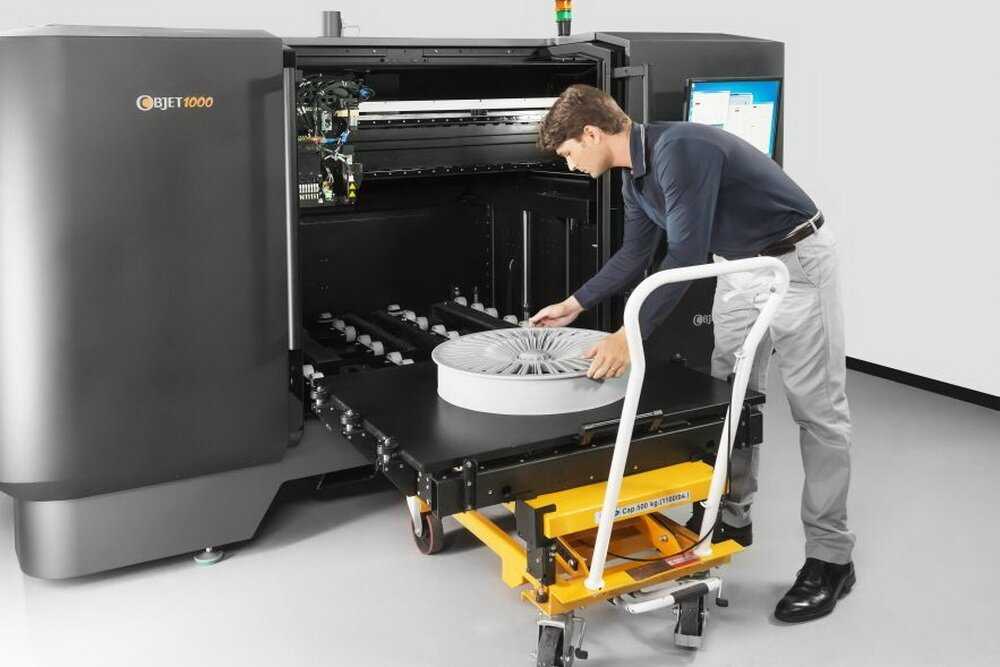 The resin is hardened with a UV light source.
Stereolithography (SLA)
SLA was invented in 1986 by Charles Hull, who also at the time founded the company, 3D Systems. Stereolithography employs a vat of liquid curable photopolymer resin and an ultraviolet laser to build the object’s layers one at a time. For each layer, the laser beam traces a cross-section of the part pattern on the surface of the liquid resin. Exposure to the ultraviolet laser light cures and solidifies the pattern traced on the resin and fuses it to the layer below.
After the pattern has been traced, the SLA’s elevator platform descends by a distance equal to the thickness of a single layer, typically 0.05 mm to 0.15 mm (0.002″ to 0.006″). Then, a resin-filled blade sweeps across the cross section of the part, re-coating it with fresh material. On this new liquid surface, the subsequent layer pattern is traced, joining the previous layer. Depending on the object & print orientation, SLA often requires the use of support structures.
Digital Light Processing (DLP)
DLP or Digital Light Processing refers to a method of printing that makes use of light and photosensitive polymers. While it is very similar to SLA, the key difference is the light source. DLP utilizes other light sources like arc lamps. DLP is relatively quick compared to other 3D printing technologies.
Continuous Liquid Interface Production (CLIP)
One of the fastest processes using Vat Photopolymerisation is called CLIP, short for Continuous Liquid Interface Production, developed by Carbon.
Digital Light Synthesis
The heart of the CLIP process is Digital Light Synthesis technology. In this technology, light from a custom high performance LED light engine projects a sequence of UV images exposing a cross section of the 3D printed part causing the UV curable resin to partially cure in a precisely controlled way. Oxygen passes through the oxygen permeable window creating a thin liquid interface of uncured resin between the window and the printed part known as the dead zone. The dead zone is as thin as ten of microns. Inside the dead zone, oxygen prohibits light from curing the resin situated closest to the window therefore allowing the continuous flow of liquid beneath the printed part. Just above the dead zone the UV projected light upwards causes a cascade like curing of the part.
Simply printing with Carbon’s hardware alone does not allow for end use properties with real world applications. Once the light has shaped the part, a second programmable curing process achieves the desired mechanical properties by baking the 3d printed part in a thermal bath or oven. Programmed thermal curing sets the mechanical properties by triggering a secondary chemical reaction causing the material to strengthen achieving the desired final properties.
Components printed with Carbon’s technology are on par with injection molded parts. Digital Light Synthesis produces consistent and predictable mechanical properties, creating parts that are truly isotropic.
Material Jetting
In this process, material is applied in droplets through a small diameter nozzle, similar to the way a common inkjet paper printer works, but it is applied layer-by-layer to a build platform and then hardened by UV light.
Material Jetting schematics. Image source: custompartnet.comBinder Jetting
With binder jetting two materials are used: powder base material and a liquid binder. In the build chamber, powder is spread in equal layers and binder is applied through jet nozzles that “glue” the powder particles in the required shape. After the print is finished, the remaining powder is cleaned off which often can be re-used printing the next object. This technology was first developed at the Massachusetts Institute of Technology in 1993.
Binder Jetting schematicsMaterial Extrusion
Fused Deposition Modeling (FDM)
FDM schematics (Image credit: Wikipedia, made by user Zureks)FDM works using a plastic filament which is unwound from a spool and is supplied to an extrusion nozzle which can turn the flow on and off. The nozzle is heated to melt the material and can be moved in both horizontal and vertical directions by a numerically controlled mechanism. The object is produced by extruding melted material to form layers as the material hardens immediately after extrusion from the nozzle.
FDM was invented by Scott Crump in the late 80’s. After patenting this technology he started the company Stratasys in 1988. The term Fused Deposition Modeling and its abbreviation to FDM are trademarked by Stratasys Inc.
Fused Filament Fabrication (FFF)
The exactly equivalent term, Fused Filament Fabrication (FFF), was coined by the members of the RepRap project to give a phrase that would be legally unconstrained in its use.
Powder Bed Fusion
Selective Laser Sintering (SLS)
SLS uses a high power laser to fuse small particles of powder into a mass that has the desired three dimensional shape. The laser selectively fuses powder by first scanning the cross-sections (or layers) on the surface of a powder bed.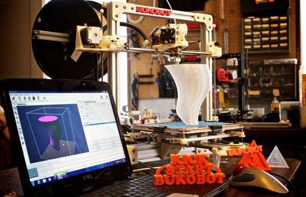 After each cross-section is scanned, the powder bed is lowered by one layer thickness. Then a new layer of material is applied on top and the process is repeated until the object is completed.
Multi Jet Fusion (MJF)
Multi Jet Fusion technology was developed by Hewlett Packard and works with a sweeping arm which deposits a layer of powder and then another arm equipped with inkjets which selectively applies a binder agent over the material. The inkjets also deposit a detailing agent around the binder to ensure precise dimensionality and smooth surfaces. Finally, the layer is exposed to a burst of thermal energy that causes the agents to react.
Direct Metal Laser Sintering (DMLS)
DMLS is basically the same as SLS, but uses metal powder instead. All unused powder remains as it is and becomes a support structure for the object. Unused powder can be re-used for the next print.
Due to of increased laser power, DMLS has evolved into a laser melting process. Read more about that and other metal technologies on our metal technologies overview page.
Sheet Lamination
Sheet lamination involves material in sheets which is bound together with external force. Sheets can be metal, paper or a form of polymer. Metal sheets are welded together by ultrasonic welding in layers and then CNC milled into a proper shape. Paper sheets can be used also, but they are glued by adhesive glue and cut in shape by precise blades.
Simplified schematics of ultrasonic sheet metal process (Image credit: Wikipedia from user Mmrjf3)Directed Energy Deposition
This process is mostly used in the metal industry and in rapid manufacturing applications. The 3D printing apparatus is usually attached to a multi-axis robotic arm and consists of a nozzle that deposits metal powder or wire on a surface and an energy source (laser, electron beam or plasma arc) that melts it, forming a solid object.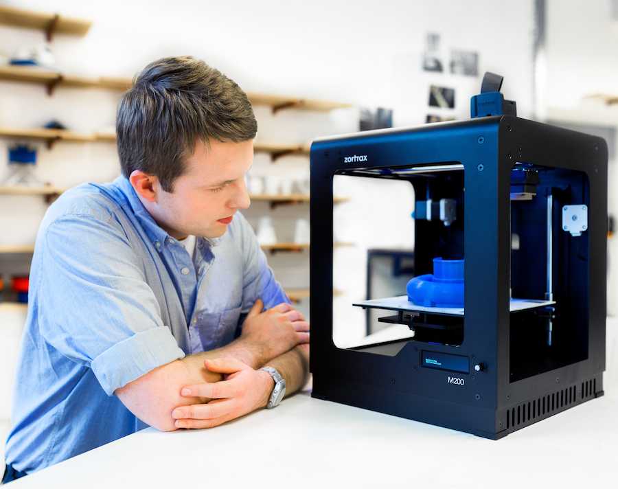
Materials
Multiple materials can be used in additive manufacturing: plastics, metals, concrete, ceramics, paper and certain edibles (e.g. chocolate). Materials are often produced in wire feedstock a.k.a. filament, powder form or liquid resin. Learn more about our featured materials on our materials page.
Services
Looking to implement 3D printing in your production process? Get a quote for a custom part or order samples on our 3D print service page.
How metal 3D printers work. Overview of SLM and DMLS technologies. additive manufacturing. 3D metal printing.
Metal 3D printing. Additive technologies.
SLM or DMLS: what's the difference?
Hello everyone, Friends! 3DTool is with you!
BLT metal 3D printer catalog
Selective laser melting ( SLM ) and direct metal laser sintering ( DMLS ) are two additive manufacturing processes that belong to the family of 3D printing using the powder layer method. The two technologies have much in common: they both use a laser to selectively melt (or melt) metal powder particles, bonding them together and creating a pattern layer by layer. In addition, the materials used in both processes are metals in granular form.
The differences between SLM and DMLS come down to the basics of the particle bonding process: SLM uses metal powders with a single melting point and completely melts the particles, while in DMLS the powder consists of materials with variable melting points. nine0014
Specifically:
SLM produces single metal parts while DMLS produces metal alloy parts.
Both SLM and DMLS technologies are used in industry to create final engineering products. In this article, we will use the term "metal 3D printing" to summarize the 2 technologies. We will also describe the main mechanisms of the manufacturing process that are necessary for engineers to understand the advantages and disadvantages of these technologies. nine0002 There are other manufacturing processes for producing dense metal parts, such as electron beam melting (EBM) and ultrasonic additive manufacturing (UAM). Their availability and distribution is rather limited, so they will not be presented in this article.
How 3D printing with SLM or DMLS metal works.
How does metal 3D printing work? The basic manufacturing process for SLM and DMLS is very similar.
1. The printing chamber is first filled with an inert gas (such as argon) to minimize the oxidation of the metal powder. It then heats up to the optimum operating temperature. nine0002 2. A layer of powder is spread over the platform, a powerful laser makes passes along a predetermined path in the program, fusing the metal particles together and creating the next layer.
3. When the sintering process is completed, the platform moves down 1 layer. Next, another thin layer of metal powder is applied. The process is repeated until the entire model is printed.
When the printing process is completed, the metal powder already has strong bonds in the structure. Unlike the SLS process, parts are attached to the platform via support structures. The support in metal 3D printing is created from the same material as the base part. This condition is necessary to reduce deformations that may occur due to high processing temperatures. nine0002 When the 3D printer's chamber cools down to room temperature, excess powder is removed manually, such as with a brush. The parts are then typically heat treated while they are still attached to the platform. This is done to relieve any residual stresses. They can then be further processed. The removal of the part from the platform occurs by means of sawing.
Scheme of operation of a 3D printer for metal.
In SLM and DMLS, almost all process parameters are set by the manufacturer. The layer height used in metal 3D printing varies from 20 to 50 microns and depends on the properties of the metal powder (fluidity, particle size distribution, shape, etc.). nine0002 The basic size of the print area on metal 3D printers is 200 x 150 x 150 mm, but there are also larger sizes of the working area. Printing accuracy is from 50 - 100 microns. As of 2020, metal 3D printers start at $150,000. For example, our company offers 3D metal printers from BLT.
metal 3D printers can be used for small batch production, but the 3D printing capabilities of such systems are more like those of mass production on FDM or SLA machines. nine0002 The metal powder in SLM and DMLS is recyclable: typically less than 5% is consumed. After each impression, the unused powder is collected and sieved, and then topped up with fresh material to the level required for the next production.
Waste in metal printing, are supports (support structures, without which it will not be possible to achieve a successful result). With too much support on the manufactured parts, the cost of the entire production will increase accordingly. nine0002
Adhesion between coats.
3D metal printing on BLT 3D printers
SLM and DMLS metal parts have almost isotropic mechanical and thermal properties. They are hard and have very little internal porosity (less than 0.2% in 3D printed condition and virtually non-existent after processing).
Metal printed parts have higher strength and hardness and are often more flexible than traditionally made parts. However, such metal becomes “tired” faster. nine0014
3D model support structure and part orientation on the work platform.

Support structures are always required when printing with metal, due to the very high processing temperatures. They are usually built using a lattice pattern.
Supports in metal 3D printing perform 3 functions:
• They form the basis for creating the first layer of the part.
• They secure the part to the platform and prevent it from deforming.
• They act as a heat sink, removing heat from the model. nine0014
Parts are often oriented at an angle. However, this will increase the amount of support required, the printing time, and ultimately the overall cost.
Deformation can also be minimized with laser sintering templates. This strategy prevents the accumulation of residual stresses in any particular direction and adds a characteristic surface texture to the part.
Since the cost of metal printing is very high, software simulations are often used to predict how a part will behave during processing. These topology optimization algorithms are otherwise used not only to increase mechanical performance and create lightweight parts, but also to minimize the need for supports and the likelihood of part distortion. nine0014
Hollow sections and lightweight structures.
An example of printing on a BLT 3D printer
Unlike polymer powder melt processes such as SLS, large hollow sections are not typically used in metal printing as the support would be very difficult to remove, if at all possible.
For internal channels larger than Ø 8 mm, it is recommended to use diamond or teardrop cross-sections instead of round ones, as they do not require support. More detailed recommendations on the design of SLM and DMLS can be found in other articles on this topic. nine0014
As an alternative to hollow sections, parts can be made with sheath and cores, which in turn are machined using different laser power and pass speeds, resulting in different material properties.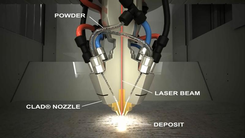 The use of sheath and cores is very useful when making parts with a large solid section, as it greatly reduces printing time and reduces the chance of warping.
The use of a lattice structure is a common strategy in metal 3D printing to reduce part weight. Topology optimization algorithms can also help design organic lightweight shapes. nine0014
Consumables for 3D metal printing.
SLM and DMLS technologies can produce parts from a wide range of metals and metal alloys, including aluminum, stainless steel, titanium, cobalt, chromium and inconel. These materials meet the needs of most industrial applications, from aerospace to medical applications. Precious metals such as gold, platinum, palladium and silver can also be processed, but their use is of a minor nature and is mainly limited to jewelry making. nine0014
The cost of metal powder is very high. For example, a kilogram of 316 stainless steel powder costs approximately $350-$450. For this reason, minimizing part volume and the need for supports is key to maintaining optimal manufacturing cost.
The main advantage of metal 3D printing is its compatibility with high-strength materials such as nickel or cobalt-chromium superalloys, which are very difficult to machine with traditional methods. Significant cost and time savings can be achieved by using metal 3D printing to create a near-clean shape part. Subsequently, such a part can be processed to a very high surface quality. nine0002
Metal post-processing.
Various post methods. treatments are used to improve the mechanical properties, accuracy and appearance of metal printed products.
Mandatory post-processing steps include the removal of loose powder and support structures, while heat treatment (heat annealing) is typically used to relieve residual stresses and improve the mechanical properties of the part.
CNC machining can be used for critical features (such as holes or threads). Sandblasting, plating, polishing, and micro-machining can improve the surface quality and fatigue strength of a metal printed part. nine0014
Advantages and disadvantages of metal 3D printing.
Pros:
1. Metal 3D printing can be used to make complex custom parts, with geometries that traditional manufacturing methods cannot provide.
2. Metal 3D printed parts can be optimized to increase their performance with minimal weight.
3. Metal 3D printed parts have excellent physical properties, metal 3D printers can print a wide range of metals and alloys. Includes difficult-to-machine materials and metal superalloys. nine0014
Cons:
1. Manufacturing costs associated with metal 3D printing are high. The cost of consumables is from $ 500 per 1 kg.
2. The size of the working area in metal 3D printers is limited.
Conclusions.
• Metal 3D printing is most suitable for complex, one-piece parts that are difficult or very expensive to manufacture using traditional methods, such as CNC.
• Reducing the need for building supports, will significantly reduce the cost of printing with metal. nine0002 • 3D printed metal parts have excellent mechanical properties and can be made from a wide range of engineering materials, including superalloys.
And that's all we have! We hope the article was useful to you.
Catalog of 3D printers for metal BLT
You can purchase metal 3d printers, as well as any other 3d printers and CNC machines, by contacting us:
• By email: [email protected]
• By phone: 8(800)775-86-69
• Or on our website: http://3dtool.ru
Also, don't forget to subscribe to our YouTube channel:
Subscribe to our groups in social networks:
In contact with
SLA Technology. How SLA 3D printing works.
Hello everyone, 3DTool is with you!
Today we will look at the basic principles of technology SLA .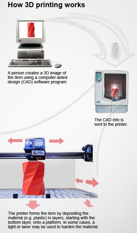 After reading this article, you will understand the main points of the printing process using this technology, the advantages and disadvantages of this method 3D printing .
On our website, you can see the list of 3D printers working on SLA technology, at this link: Catalog of 3D printers printing on SLA / DLP technology
Technology 3 D printing SLA
Stereolithography (SLA) is an additive manufacturing process that achieves the result by means of resin polymerization. AT SLA print, an object is created by selectively curing a polymer resin, layer by layer, using an ultraviolet (UV) laser beam. The materials used in SLA printing are photosensitive thermoset polymers that are available in liquid form.
SLA is known as the first 3D printing technology : its inventor patented this technology back in 1986 . When you need to print parts with very high precision or a smooth surface, 9 comes to the rescue. 0004 SLA . In this case, it is the most cost-effective and efficient technology 3D printing . The best results can be achieved only if the operator of the equipment on which the printing process takes place is familiar with the technology and some of the nuances. That is, he has the necessary qualifications.
SLA shares many characteristics with Direct Light Processing (DLP ), another photopolymerization technology. For simplicity, both technologies can be considered equal. nine0014
SLA process
Here's how the process works:
1) 2) 3)
1) A platform is placed in the tank with liquid photopolymer, at the same height level from the resin surface.
2) The UV laser then selectively cures the required areas of the photopolymer resin according to a predetermined algorithm.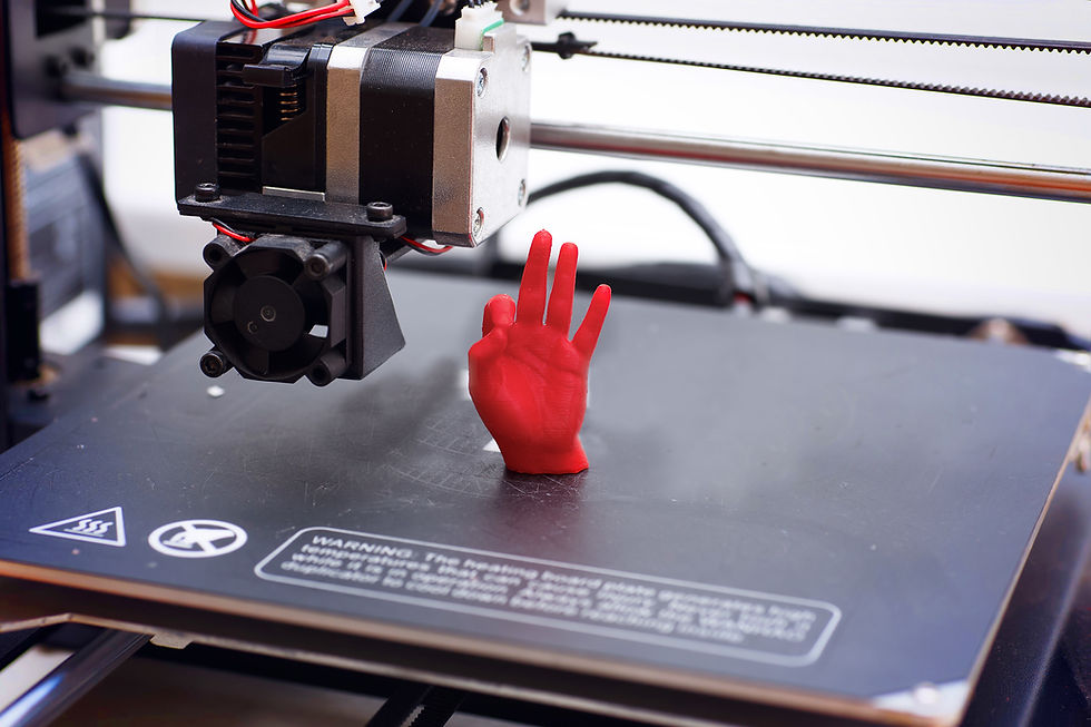
The laser beam is focused on a given path using a set of mirrors called galvos. Then the entire cross-sectional area of the model is illuminated. Therefore, the resulting part is completely solid.
3) When one layer is finished, the platform moves to a safe distance and the mixing foot inside the bath mixes the resin. nine0014
This process is repeated until the part is printed. After printing, the part is not fully cured and requires further post-processing under the UV Lamp . At the end of UV illumination, the part acquires very high mechanical and thermal properties.
The liquid resin solidifies through a process called photopolymerization: during solidification, the monomer carbon chains that make up the liquid resin are activated by an ultraviolet laser and become solid, creating strong, inextricable bonds with each other. nine0014
The photopolymerization process is irreversible, and there is no way to convert the resulting parts back into a liquid state. When heated, they will burn, not melt. This is because the materials that are produced with SLA technology are made from thermoset polymers, as opposed to thermoplastics that FDM uses.
Worksheet SLA printer
Specifications SLA printer
On SLA systems, most print settings are set by the manufacturer and cannot be changed. The only inputs are the layer height and the part orientation ( last, locates the supports ).
The typical layer height in a SLA print ranges from 25 to 100 micron .
The lower the layer height, the more accurately the complex geometry of the model will be printed, but at the same time the printing time and the likelihood of failure will increase. A layer height of 100 microns is suitable for most common geometries and is the golden mean.
Another important parameter for the operator is the size of the platform. It depends on the type of SLA printer. There are two main types: orientation top to bottom and orientation from bottom to top .
In the first case, the laser is above the tank, and the part is face up. The platform sits at the very top of the resin vat and moves down after each layer is sintered.
Schematic SLA Top Down Printer
With " bottom up " on SLA printers , the light source is placed under the resin tank (see picture above) , and the part is built upside down.
The tank has a transparent bottom with a silicone coating that allows the beam of light to pass through but prevents the cured resin from sticking. After each layer, the cured resin separates from the bottom of the tank as the platform moves up. This is called sintering step .
Schematic SLA bottom up printer
The orientation " bottom to top " is mostly used in desktop printers like Formlabs. The " top to bottom " orientation is used in the industrial SLA printer .
Printers SLA " bottom up " are easier to manufacture and operate, but the size of the possible print will be smaller, since the forces applied to the part during the sintering stage can cause printing to fail.
Top-down printers, on the other hand, can print very large parts without much loss in accuracy. The wide possibilities of such systems naturally cost more. nine0014
The following are the main characteristics and differences between the two orientations:
| "From top to bottom " | |
| Pros: | |
| lower cost | |
| nine0013 Wide market availability | |
| Minuses: | |
| Small platform size | |
| Smaller range of materials | |
| Requires additional post-processing due to extensive nine0014 use of supports | |
Popular brands:
FORMLABS
Printable area: Up to 145 x 145 x 175 mm
Typical layer height and print accuracy: 25 to 100 µm and ± 0. 5% (lower limit: ± 0.010 to 0.250 mm) respectively
| "Down up" nine0014 | |
| Pros: | |
| Very large platform | |
| Faster Print Time | |
| Minuses: | |
| nine0013 High price | |
| Qualified operator required | |
| Material change involves emptying the entire tank | |
Popular manufacturers:
PRISMLAB
Print area size: Up to 1500 x 750 x 500 mm nine0014
Typical layer height and print accuracy: 25 to 150 µm and ± 0.15% (lower limit ± 0.010 to 0.030 mm) respectively
Support during 3 D printing
Supports are always required at Print SLA . Structural structures are printed from the same material as the part and must be manually removed after printing.
Part orientation determines the location and amount of supports. It is recommended that the part be oriented so that surfaces that require maximum quality do not come into contact with supports. nine0014
In different types of SLA printers, support is used in different ways:
For top - down printers , support requirements are the same as FDM . They are essential for accurate printing of overhangs and bridges ( the critical overhang angle is typically 30 degrees ).
The part can be oriented in any position and is usually printed flat to minimize the number of supports and the total number of layers. nine0014
In printers like " from bottom to top " everything is more complicated. Overhangs and bridges also need to be supported, but minimizing the cross-sectional area of each layer is the most important criterion.
Forces applied to the part during the sintering step can cause it to come off the platform. These forces are proportional to the cross-sectional area of each layer.
For this reason, the parts must be oriented at an angle, and minimizing supports here is not a primary concern. nine0014
On the left - a detail oriented on the SLA printer "from top to bottom" (support minimization).
On the right is a part oriented on the SLA printer "from the bottom up" (minimizing the cross-sectional area).
Removing supports for an SLA printed part
Curl
One of the biggest problems with the accuracy of parts made with SLA is twisting. This problem is similar to the deformation in FDM when materials shrink.
During curing, the resin shrinks slightly when exposed to the printer's light source. When shrinkage is significant, large internal stresses develop between the new layer and the previously cured material, causing the part to twist.
Adhesion (sintering) between layers
nine0004 SLA printed parts have isotropic mechanical properties. This is due to the fact that one pass UV beam is not enough to completely cure the liquid resin.
Further passes help the previously hardened layers to fuse together. In fact, in the SLA of printing, curing continues even after the printing process is complete.
To achieve the best mechanical properties, parts printed using this technology should be post-cured by placing them in a chamber under intense ultraviolet radiation ( and sometimes at elevated temperatures ).
This greatly increases the hardness and heat resistance of the SLA part, but does not make it stronger. Rather the opposite.
For example.
Test specimens printed with standard clear resin on a SLA desktop printer have, after curing, almost 2 times greater tensile strength ( 65 MPa compared to 38 MPa) after curing.
Can operate under load at higher temperatures ( 58 degrees Celsius, compared to 42 degrees ), but their elongation at break is less than half ( 6.2% compared to 12% ).
If you leave the part in the sun, then nothing good will come of it.
Prolonged exposure to ultraviolet radiation has a detrimental effect on physical properties and appearance. The part may curl, become very brittle, and change color.
For this reason, before using the part, it is recommended to apply a spray of transparent acrylic paint resistant to UV .
SLA media
Materials for SLA printing are available in the form of liquid resin. The price per liter of resin varies greatly - ranges from $50 for standard material to $400 for specialty materials such as casting or dental resin.
Industrial systems offer a wider range of materials than desktop systems SLA printers, which give the designer more control over the mechanical properties of the printed part.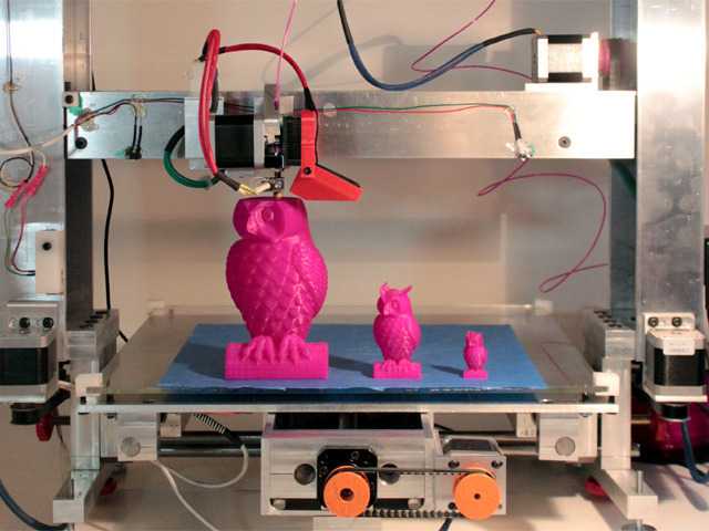
SLA materials ( thermosetting materials ) are more brittle than materials made using FDM or SLS ( thermoplastics ) and for this reason SLA parts are not typically used for functional prototypes that will be subjected to significant stress. However, new advances in materials development may change this in the near future. nine0014
The following table lists the advantages and disadvantages of the most commonly used resins:
| Material | Features |
| Standard resin | + Smooth surface Relatively fragile part nine0014 |
| transparent resin | + Transparent material - Requires post-processing for Presentable appearance |
| casting resin | + Used to create mold templates + Low ash after burnout |
| Rigid or durable resin | + ABS-like or PP-like mechanical properties - Low thermal resistance |
| High temperature resin | + High temperature resistance + Used for injection molding · - High price nine0014 |
| dental resin | + Biocompatible + High abrasion resistance · - High price |
| Rubber-like resin | + Rubber-like material - Poor printing accuracy |
Post-processing SLA 3D printing
Parts printed with SLA technology can be processed to a high quality using various methods such as sanding and polishing, staining and mineral oil treatment. Widely developed articles about post-processing can be found on the Internet.
Transparent resin housing cover for electronics in various finishes. From left to right: removal of the main support, wet sanding, UV irradiation, acrylic and polishing
Advantages and disadvantages of SLA
Pros:
-
SLA 3D printers can produce parts with very high dimensional accuracy and complex geometries.
-
The parts will have a very smooth surface, making them ideal for visual prototypes, for example.
-
Special materials are available such as clear, flexible and cast resins. nine0014
Cons:
-
Parts printed using SLA technology tend to be fragile and not suitable for functional prototypes.
-
The mechanical properties and appearance of these parts deteriorate over time.
 They are adversely affected by exposure to sunlight.
 -
Supports and post-processing when printing are always required.
nine0014
The main characteristics of the SLA are shown in the table:
materials
Photopolymer resins (thermosetting
materials)
Dimensional accuracy
± 0.5% (lower limit: ± 0.10 mm) - domestic
± 0.15% (lower limit ± 0.01 mm) - industrial nine0014
typical size
print area
Up to 145 x 145 x 175 mm - for desktop printers
Up to 1500 x 750 x 500 mm - for industrial
Total layer thickness
25 - 100 µm
Support
Always required nine0014
(Needed to make an accurate part)
Total
-
SLA print is best for producing visual prototypes with very smooth surfaces and very fine detail.
Learn more