Leadscrew 3d printer
Helix Blog | Lead Screws in 3D Printer
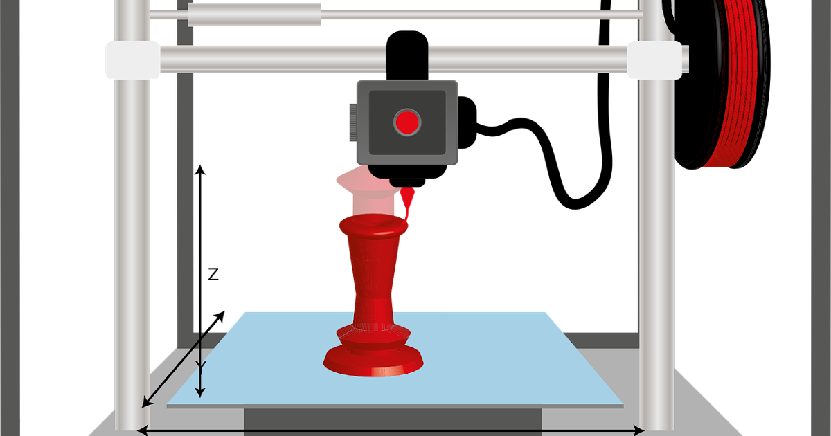
With a 3D printer, product developers can quickly and cost effectively create actual physical parts of product designs directly from product design data. Just as a desktop printer produces type on a 2D page, a 3D printer builds a physical object in 3D space, layer by layer.
Rapid Prototyping 3D Multi-Material Printers
For many of today’s manufacturing organizations, 3D printers have become a fixture for the rapid prototyping of parts and products prior to their release for manufacture. With a 3D printer, product developers can quickly and cost effectively create actual physical parts of product designs directly from product design data. Just as a desktop printer produces type on a 2D page, a 3D printer builds a physical object in 3D space, layer by layer. The majority of 3D prints are used for design interrogation and evaluation purposes. Some parts produced on a 3D printer are production-ready. Still others serve as the basis for creating molds for investment castings.
The benefits of using a 3D printer to rapid prototype parts versus the historical practice of machining prototypes as preview parts is that it’s faster and less expensive. However, not all 3D printers are created equal. This article will examine the advantages of using precision engineered lead screws for driving linear motion control applications in 3D printing systems.
Lead Screws Outperform Belt Drives in 3D Printers
Many of the 3D printers on the market today utilize belt-drive technology, which results in inferior performance characteristics when compared to precision-engineered screws. With belt-drive technology, accuracy and repeatability can be issues because belt-drives simply have more play in them, delivering less-precise linear motion control than precision formed or
thread-rolled screws.
Because of the imprecision associated with belt-drive technology, 3D printers that use belt-drives for linear motion control output parts of less than optimal quality, with undesirable surface patterns, and with less resolution on certain types of part features, such as holes and cavities.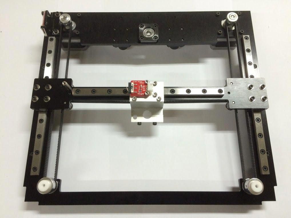 Screws, on the other hand, provide higher levels of accuracy, repeatability, and performance when used in 3D printers. Thus, 3D printers that operate with lead screws output more precise, better quality parts.
A Screw's Function in a 3D Printer
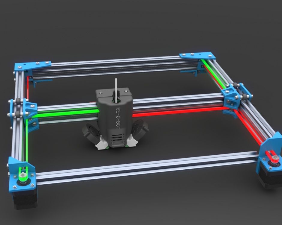
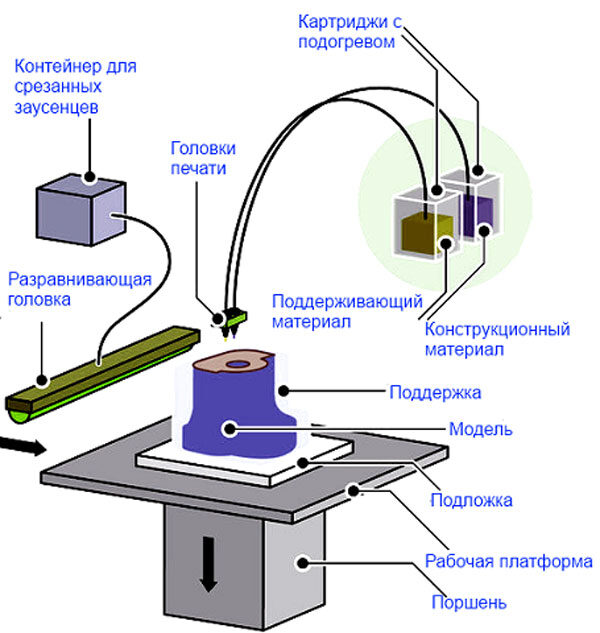
Within a 3D printing application, screws are typically driven by a stepper motor and guided by profile rails on the X and Y axes. Precision engineered acme nuts are connected to the carriage mechanism. All axes are actuated with a stepper motor- driven screw with an anti-backlash nut, and move along linear ball bearing guides.
An important advantage of the screw-rail configuration for controlling linear motion in 3D printers is that it requires a fraction of the number of components that are necessary for belt-driven 3D printers and takes much less time to assemble.
Compared to belt-drives, which deliver linear motion with repeatability of ±0.1 mm/m and a layer height of 100 microns in 3D printing applications, screws offer linear motion with repeatability of ±0.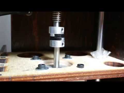 02 mm/m and a layer height of 50 microns, making them a lot more precise and accurate for controlling 3D printer performance.
Precision-grade screws have increasingly become the preferred option for low-cost, desktop 3D printers because they deliver the accuracy, repeatability, and performance that users demand - all at at an affordable price. In other words, 3D printer designers no longer need opt for belt drives for controlling linear motion in 3D printers just to keep the cost down. With precision-engineered screws, you can produce high-resolution parts while reducing cost.
Use Helix to Build Top-Performing, Cost-Effective 3D Printers
Contact Helix Linear Technologies to learn how you can use precision-engineered lead and acme screws to develop cost-effective, high-performance 3D printers and rapid prototyping systems. Helix offers a wide array of highly configurable lead and acme screw assemblies that can provide the accuracy, repeatability, and performance that you need to outperform other 3D printing systems on the market.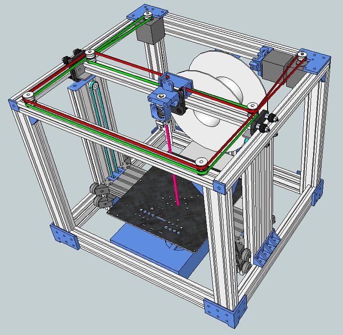
Download our "How Are Lead Screws Used in a 3D Printer?" Case Study
This 4 page case study includes more information about how screws control the precision needed for 3D printers.
Products
Lead Screws
Acme Screws
Lead Screw Nuts
Additional Reading
Are Lead Screws for You?
Lead Screw Actuators Enable World Class Rail Car Design
Additive Manufacturing
diy 3d printer - Are there practical reasons to NOT use a stepper motor with lead screw for the X and or Y axes?
I am going to answer this as someone who actually did rework their Prusa i3 fleabay clone to use leadscrews for all axes. Before digging into the matter, the backlash issue can be solved easily with spring-loaded brass nuts, kinda like how ballscrews work. That's the simplest problem to solve though as there are a lot of other issues.
Short version / tl;dr
Hardware can't handle that many microsteps.
Crosstalk and motor inductance limit speeds and acceleration.
Print quality suffers in really weird ways because of (2).
Leadscrews are not made for quick movement over extended periods of time and will wear, even with grease.
You'll need additional bearing surfaces to prevent your motors from grinding themselves apart, and to eliminate backlash due to the flex couplings.
The system becomes a lot more prone to highly destructive failure modes.
Long explanations
First
You're going to notice is that you're constrained to horribly, horribly slow movement and acceleration rates. My screws are 8 mm screws, with 8mm pitch. That means it takes 200 steps to travel 8 mm. Multiply by 1/16th microstepping, and that's 3200 microsteps per 8 millimeter of travel. Multiply by whatever speed you're trying to print at, then the number of axes you're using, and you'll find that your RAMPS board starts to stutter on complex moves if you print fast enough.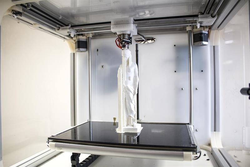
Second
You'll quickly hit the inductance limits of your motors. At "standard" power levels (ones that don't fry my knockoff NEMA17 motors), even after switching to 24 V for the entire setup, the fastest I could spin my motors was about 5 revolutions per second, which translates to 16,000 microsteps per second with 8mm pitch screws. For reference that means that under ZERO load, the fastest my N17 w/ 8 mm pitch could travel, is about 40 mm/s.
You're basically running the motor coils at several kilohertz, which means you have to be really careful about keeping your wires separate and shielded to prevent crosstalk, in addition to the fact that as your step frequency goes up, your step torque goes down dramatically. Not only does this limit the weight of the bed that the motor is capable of pushing at a given speed, but you even have to worry about the inertia of the motor and bed much more than with a belt-driven system. So instead of 30 mm/s jerk with 200 mm/s2 acceleration, suddenly you're limited to, say, 5 mm/s jerk and 40 mm/s2 acceleration.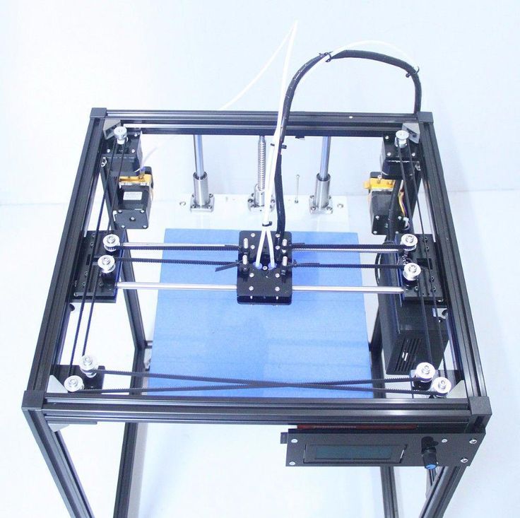
As mentioned, for best results, the whole system needs to be converted to 24 V, and not all boards are configured for this to be easily done. My cheap RAMPS clone only needed a single diode removed and everything else was fine, but YMMV in this regard.
You could solve this particular problem by gearing the motors down, but at that point you've now introduced a new source of backlash either between the gear teeth or in the belt drive system, and kinda defeated the point.
Third
Due to this effect, is that you run into extrusion pressure artifacts. Basically, the plastic in the nozzle is a fluid, a very viscous one, being forced through a small hole. The fluid pressure will "lag" somewhat behind what the extruder motor thinks is happening.
The end result is that while you're accelerating, the lines you're laying are thinner than they should be, and will be thicker than they should be while decelerating, and you tend to get weird "globs" on each corner when you come to a stop.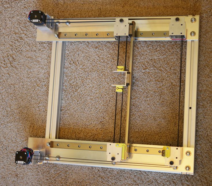 For me, with a 0.4 mm nozzle, 0.8 mm line width, and 0.2 mm layer height, these artifacts actually completely offset the additional accuracy I was getting with a tightly-coupled leadscrew with spring loaded dual nuts on it. The parts ended up being even less dimensionally accurate than before, with very strange deformities.
There ARE settings you can use in the firmware to try and combat this specific effect, but the process is tedious and takes a lot of trial-and-error, and recompiling the firmware every 30 seconds is annoying, not to mention the variables are dependent on line width, speed and acceleration settings, and layer height, so you have to recompile your firmware any time you want to change the print quality. Super, super annoying.
Fourth
Leadscrews aren't actually designed for this. The constant back-and-forth motion will wear the brass nuts and even the steel threads of the screws over time. You end up with a black powdery residue on everything underneath the screw, which, in the X axis, typically also means your print.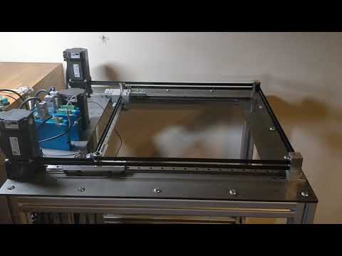 Nobody wants steel powder messing up their layer adhesion.
In my case I used Superlube, which is a silicone/PTFE grease, to help prevent this problem, but that only works so well when you've got spring-loaded brass nuts. Eventually they push most of the lube out. Additionally, the lube tends to grab and hold any metal powder that does form, accelerating wear in areas that are still lubricated.
Fifth
Bearings. Turns out motors have internal bearings, that generally suck and aren't made for heavy loads in any direction. I found that out when my Y-axis N17 motor failed because the bearing did, and spread powder all over the coils, some of which got pushed through the enamel and shorted the wires out.
Additionally, because tiny amounts of misalignment turn motors into shrapnel in a hurry, you're almost certainly going to be using flex couplings. Flex couplings have a certain amount of yield to them axially, and are primarily designed to be under compression loads, and tend to fail when stretched repeatedly.
For the Z axis this is normally not an issue because the whole system is held down by gravity, but in the X and Y axes, you'll get some weird offsets of even a millimeter or two each time the carriage or bed switches directions. So you'll want to make sure that the motors aren't load bearing themselves, and the screw remains locked relative to the frame while still being able to rotate.
You can accomplish this by having a ring fastened to each end of the leadscrew that either pushes on a thrust bearing or rides in a regular ball bearing. Ideally, you can do both, but this turns into an expensive venture with a whole lot of brackets in odd places that you may not have space for. I ended up losing about 20 mm of bed travel solving this problem.
Sixth
You need to think about what happens when a component fails. For me, it was my endstops. The first failure was from the crosstalk issue I mentioned above. Y-stops triggered, bed started shifting towards the front of the printer over time, and eventually the printer started trying to move the bed through the front of the printer frame.
It was successful.
The second time was simply the endstop switch failing mechanically. Belt travel stops at the pulley. Leadscrews go all the way to the end of the screw, and because they're geared so much lower than belts are, there's a lot more torque involved. I destroyed my printer frame three separate times because of this problem, and once more when the Y-axis flex coupling snapped. This allowed the motor to spin the screw easily in one direction but not in another - which this time forced the print bed backwards instead of forwards, yanking the Y motor through its bracket and the frame again.
Conclusion
X/Y screws are not necessarily a bad idea, simply an expensive and tedious one in 3D printing. They're much better suited to low-feedrate applications like CNC mills, mechanical engravers, and the like. You may notice that even high-accuracy applications like laser printers tend to have belt-fed carriages rather than screw-driven ones. Screws are much better suited to high load, low-speed applications, and printers tend to be the opposite of that.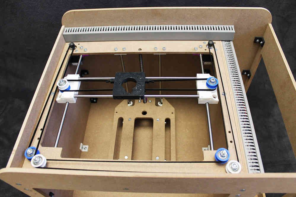
If you're trying to eliminate backlash due to the belts not being tight enough, as I was, the answer is to make a better printer. I couldn't tighten the belts enough to get my prints accurate before the motors started failing, because I didn't have the motor-end pulley supported by a bearing. Start there, literally just support on either side of the pulley on the motor shaft with a small bearing braced against the frame to take the radial load off the motor. If your belts are stretching too much, use steel-core GT2 belt. If your system is overall just sloppy, build a more robust system. My current project is a Hypercube Evo, and I found a supplier that makes steel-core GT2 belt. I'm going to use that to maximize rigidity in the CoreXY belt system. The frame is made from 30x30 mm T-slot extrusions, with 12 mm Z-axis rods and 10 mm X/Y axis rods. Bigger, more expensive components that are way more robust and will flex much less than the 400 mm long 8 mm rods on my cheapo printer.
Hope this helps.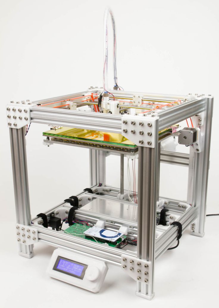 (edited to get my math right on the microsteps)
Leadscrews: an extended experience of long-term use
Sandbox
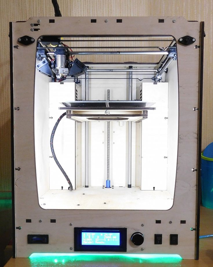
So, the printer has already printed enough for me to tell absolutely everything about the screws.
The original idea was that the belts need to be tightened, and the print resolution on them is not very high. Decided to try the screws in connection with this.
First, let's talk about speed. The achieved 100mm/s proved to be unstable. In reality, the initially found 60 mm / s turned out to be reinforced concrete stable. What is most offensive is that the speed cannot be raised even on movements without printing. That is, the printer constantly crawls 60mm / s, regardless of the job. What generates a bunch of snot on the models, the retract does not help much. This is partly a feature of my extruder: the hot zone is quite large, and there is a lot of liquid plastic. nine0003
In an attempt to increase speed and to complete the experiment, I had very, VERY thick 60mm NEMA17 sliders:
The idea was simple: larger sliders would give more torque and holding moment, which is so necessary for the lead screws.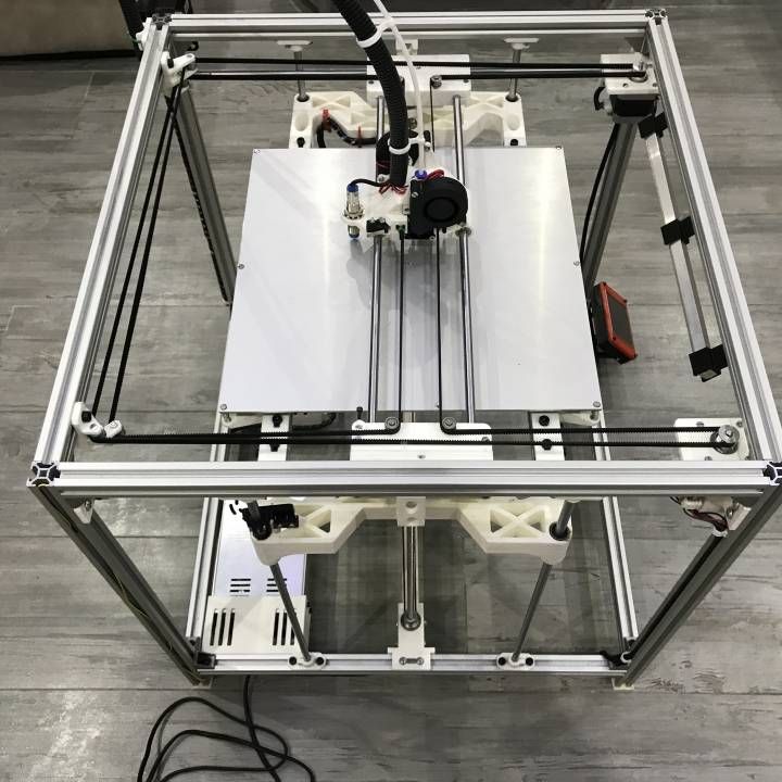 But in real life, everything turned out to be almost the opposite: it was not possible to get stable 60mm on them. In the course of the experiments, I reached the full step mode of the stepper motor, but this did not help either. In addition, the printer just yelled from resonant phenomena. These engines turned out to have too much magnetic coupling (? I don’t know how to call it correctly), and they do not digest high speeds. As a result, I sent them to supply plastic to another printer. nine0003
Speaking of noise... The printer is noticeably louder than it was on the belts. And it's not just the aforementioned resonant phenomena and the 1/4 step mode. The point is the backlash of the nut-lead screw connection. When changing direction, a distinctly audible knock is heard. Sleep next to him is impossible in principle, a knock is heard even behind two closed doors.
Not all is well with the nuts themselves either. If the screw is under the table (as with the Y-axis), then everything is more or less smooth, but if it is above the table, as in the case of the X-axis, then the table will always be strewn with black chips that fall off the nut as it wears out.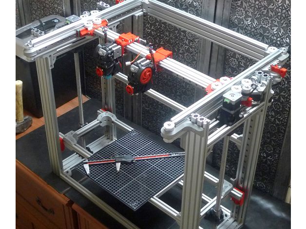 nine0003
Nut play must also be constantly monitored. If the backlash becomes more than 0.1 mm, you can forget about accurate printing. This is due to the fact that a heavy X-carriage (as in my case) after a stop by inertia chooses backlash in the opposite direction. And as a result of this, X-wobbling and Y-wobbling are added to the notorious Z-wobbling characteristic of i3, and any printout turns into something unforgettable in the most terrible sense. Software backlash compensation partly saves, but only up to 0.1 mm. The next step is to replace the nut. nine0003
I had some misalignment of the nut with the screw in the X axis, and the nut was eaten very vigorously, in about 400 hours of printing. The slightest unnecessary friction - and wear increases almost exponentially. Here someone described the solution to the backlash problem in the form of 2 nuts and a spring between them (I did not find the link), and so: this is nonsense. Nuts will gobble up even faster than in my case, and even doubly cover everything with bronze chips (this is true for X and Y - axes that constantly rotate). By the way, here is a photo of a new and used nuts:
Wear visible to the naked eye.
Another non-obvious minus: when the table is parked, and it needs to be pulled out for applying abs-juice or cleaning, you have to tediously turn the screw to do this, while with straps you could just pull the table towards you.
Based on all of the above, I sum up the disappointing result: the screws are not applicable for a 3D printer, except for the Z axis. I'm getting ready to return to the belts. Don't repeat my mistake.
Adios nine0003
Subscribe to the author
Subscribe
Don't want
4
Techno Print 3D Company
This is our first review of the most popular and inexpensive 3D printers for 2020. The list will include the best-selling devices in two price ranges (up to 30 tr and up to 60 tr). Printers working with both plastic filament (FDM) and photopolymers (LCD/DLP) will be presented.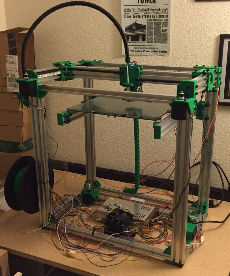 This list will always be up to date, as it is periodically updated and supplemented. Read more→
The Chinese company Dazz3D announces the launch of the project on KickStarter and accepts pre-orders for Dazz3D Basic and Dazz3D Pro 3D printers. These revolutionary new devices are aimed at both the professional and amateur markets. Read more→
We all know that precise calibration of the 3D printer desktop is the foundation and the key to successful printing on any FDM printer. In this article we will talk about the main and most popular ways to level the "bed". So, as mentioned above, 3D printing without desktop calibration is impossible. We face this process Read more→
It's hard to go through a day today without hearing about 3D printing technology, which is bursting into our lives at an incredible speed. More and more people around the world are becoming addicted to 3D printing technology as it becomes more accessible and cheaper every day. Now almost anyone can afford to buy a 3D printer, and with the help of Read more→
The FormLabs Form 2 and Ultimaker 3 are perhaps the most popular 3D printers today, capable of high quality printing with incredible surface detail.