Dimensional accuracy 3d printer
Dimensional Accuracy
Dimensional Accuracy
The dimensional accuracy of your 3D printed parts can be extremely important if you are creating large assemblies or parts that need to precisely fit together. There are many common factors that can affect this accuracy such as under or over-extrusion, thermal contraction, filament quality, and even the first layer nozzle alignment. Simplify3D includes several tools to help cope with these common issues, so we will explain each one in more detail below.
Common Solutions
First Layer Impact
Settings for your first layer can have an impact on dimensional accuracy. If your nozzle is too high or too low for the first layer of your print, it can drastically affect the next 10-20 layers of the part. For example, if you are printing a 0.2mm thick layer, but your nozzle is only positioned 0.1mm away from the bed, then this extra plastic may create a first layer that is a bit too large. Future layers can also be affected by the extra plastic on this layer, which creates several oversized layers at the bottom of the part. So before you spend too much time trying to perfect the dimensional accuracy of your prints, you need to verify that your measurements are not being affected by the first layer position. One common way to do this is by printing a model with 50-100 layers and then only measuring the top 20 or so layers. These top layers are far away from the very first layer that was printed on the bed, so it minimizes the impact of nozzle positioning. Before proceeding to the sections below, make sure that your measurements follow these guidelines.
Under or Over-Extrusion
Now that you know you are using accurate measurements that are not affected by the first layer position, the next setting you want to verify is your extrusion multiplier. This setting affects the flow rate for the entire print. If the extrusion multiplier is too low, you may start to see gaps between perimeters, holes in your top surfaces, and parts that are smaller than their intended size. If your extrusion multiplier is too high, you may notice top layers that tend to bulge upwards and parts that are larger than intended. So again, before proceeding to the sections below you will want to verify that your extrusion multiplier is properly calibrated. For more advice on these topics, please see the Under-Extrusion and Over-Extrusion sections.
Constant Dimensional Error
If you have completed the steps above and the prints are still not sized correctly, Simplify3D offers the ability to precisely offset the edges of your print to account for these differences. This setting is labeled “Horizontal size compensation” and can be found on the Other tab of your Process Settings. For example, setting this value to -0.1mm will shrink your model by 0.1mm in the X and Y directions. This setting works best when the dimensional error is consistent, even when printing models of different sizes. For example, if the part is always 0.1mm too large, regardless of if the model is 20mm wide or 100mm wide, then this setting can easily account for that difference.
Increasing Dimensional Error
If you notice that the dimensional error tends to increase as you print larger parts, then there is a different setting you can adjust. For example, if your print was 0.1mm too small for a 20mm wide part, but increased to 0.5mm too small for a 100mm wide print, then it is likely the problem may be due to thermal contraction. This can be a common issue for high temperature materials like ABS, since plastic tends to shrink as it cools. Simplify3D includes several options to help with this. First, you need to determine the shrinkage percentage. In the above example, the part is shrinking by 0.1mm over a 20mm print, so the shrinkage percentage is 0.1 / 20 = 0.5%. The easiest way to fix this error is to double-click on your model in the Simplify3D interface and set the scale to 100.5%. If you find yourself making these changes consistently, you can also setup an Import Action to perform this scaling automatically each time you import a new model. Please see this video for more details about creating Import Actions.
Related Topics
What is dimensional accuracy in 3D printing and how do you achieve it?
What is dimensional accuracy in 3D printing and how do you know which technology will yield the most accurate results? This article compares the expected dimensional accuracy of various 3D printing technologies to help designers and engineers choose the right solution for their application.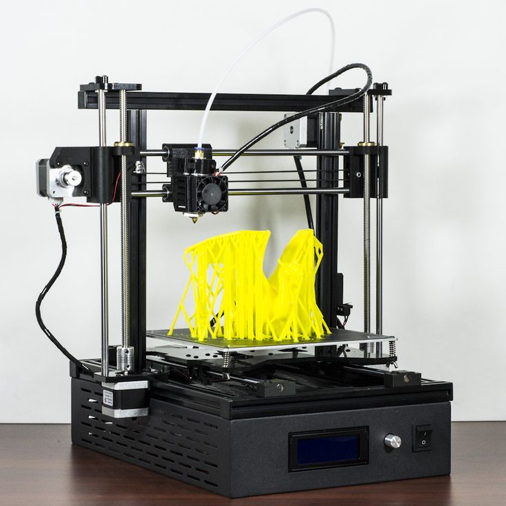
Dimensional accuracy in 3D printing refers to how closely the measurements in your CAD design match those of the part once it’s printed. It’s a key consideration if your components need to fit together precisely or if you’re manufacturing sizable assemblies.
Many factors can positively (or adversely) affect the dimensional accuracy of your 3D printed parts, including the quality of your filament , thermal contraction and/or over- or under-extrusion (for FDM specifically). Other factors, including the quality of the machine, machine calibration, quality of resin and post-processing , can also affect the dimensional accuracy of your parts.
When it comes to achieving dimensional accuracy, each additive manufacturing technology has its strengths and weaknesses. The two most important factors that govern whether your printed part will match its design specifications, apart from the technology itself, are its design and materials.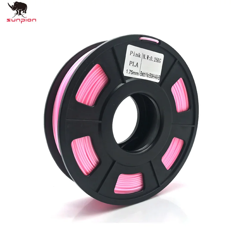
In this article, we’ll compare the expected dimensional accuracy of the 3D printing technologies we offer to help designers and engineers choose the right solution for their applications.
How do materials affect dimensional accuracy?
Accuracy in 3D printing depends in part on the materials you use. In many cases, enhancing specific material properties will mean sacrificing accuracy. For instance, a standard SLA resin will produce more dimensionally accurate parts than a flexible resin.
For parts where high accuracy is critical, we recommend you use standard printing materials. High-quality, industrial materials, such as Nylon and Ultem, are both strong and accurate will be more expensive.
How do you measure dimensional accuracy in 3D printing?
To quantify the dimensional accuracy of 3D printed parts, we use the following parameters.
-
Dimensional tolerance- quantitative values from machine manufacturers and material suppliers that state the expected accuracy of parts. These are defined with respect to well-designed parts on well-calibrated machines.
-
Warping or shrinkage - the likelihood a part will warp or shrink while printing. While design plays a big role in determining whether parts will warp or shrink, some processes are inherently more prone to warping or shrinkage than others.
-
Support requirements - for many 3D printing technologies, the number of supports you have to remove after printing will affect the accuracy of a part’s surfaces and features.
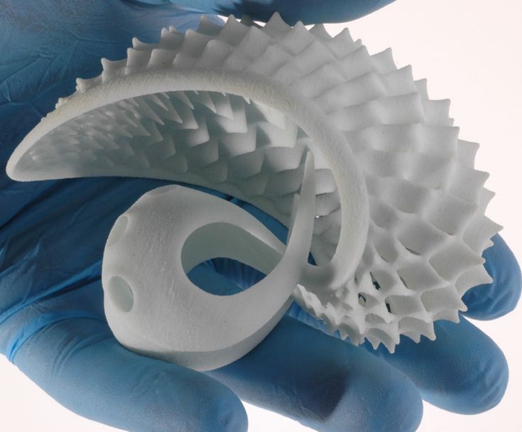
Dimensional accuracy of FDM 3D printing
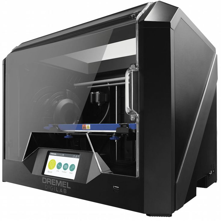
FDM (fused deposition modeling) is ideal for low-cost prototyping, where form and fit are more important than function.-kupit-v-soin-store.ru-2.png) It’s the most accessible form of 3D printing, and one of the most widely used across most industries.
It’s the most accessible form of 3D printing, and one of the most widely used across most industries.
FDM machines produce parts by extruding a thermoplastic material onto a build plate one layer at a time, from low-cost PLA or ABS for prototyping to industrial aerospace parts made from high-strength thermoplastics like Nylon and Ultem.
Typically, small parts are limited by extrusion spot size and gantry positioning accuracy. On the flip side, large parts are limited by shrinkage due to non-uniform cooling that comes from the temperature gradient mid-build.
For large parts, this can lead to big variations in temperature across the build platform. As different areas of the part cool at different rates, internal stresses cause the print to deform, leading to warping or shrinkage. Solutions like printing rafts, heated beds and radii at sharp edges and corners help to reduce this effect.
Lastly, FDM parts require support structures. Even though build prep software takes into account the supported sides and will often make adjustments to hit the ideal dimensions, post-processing can introduce some dimensional inaccuracy for parts that require a significant amount of support material.
Of course, different materials are more prone to warping than others. ABS is more susceptible to warping than PLA , for instance.
Finer points for dimensional accuracy of FDM
| Parameter | Finer details|
| ---------- | ---------- |
| Dimensional tolerance | prototyping (desktop): ± 0.5% (lower limit: ± 0.5 mm) industrial: ± 0.15% (lower limit: ± 0.2 mm) |
| Shrinkage/warping | Thermoplastics that require a higher print temperature are more at risk. Adding a radius on the bottom edge in contact with the build plate or a brim is recommended. Shrinkage usually occurs in the 0.2 - 1% range depending on the material. |
| Support requirements | These are essential to achieve an accurate part. Required for overhangs greater than 45 degrees. |
Curious about the cost and material options for FDM?
Our FDM 3D printing services Get a free, instant quote
Dimensional accuracy of SLA 3D printing
SLA (stereolithography) printers use lasers to UV cure specific areas of a resin tank to form solid parts one cross-section at a time. These cured areas, however, are not at full strength until post-processing with UV. As well, the typical printing angles and orientations of SLA can lead unsupported areas to sag.
This effect is especially prevalent in taller SLA parts, which have dimensional discrepancies thanks to the layer-by-layer build process. Dimensional discrepancies can occur because of the peeling process used by some SLA printers.
Dimensional discrepancies can also occur because of the peeling process used by some SLA printers. The pulling force during the peeling process can cause the soft print to bend which again can accumulate as each layer is built up.
Resins that have higher flexural properties (less stiff) are at a greater risk of warping and may not be suitable for high-accuracy applications.
SLA parts also require the parts to be anchored to the build plate and that angles lower than 45 degrees be supported. Support removal from SLA parts can often be considered an art and requires highly skilled technicians to remove supports and provide light sanding to those surfaces.
Finer points for dimensional accuracy of SLA
| Parameter | Finer details |
|---|---|
| Dimensional tolerance | Prototyping (desktop): ± 0.5% (lower limit: ± 0.10 mm) Industrial: ± 0.15% (lower limit: ± 0.01 mm) |
| Shrinkage/warping | Likely for unsupported spans. |
| Support requirements | Essential to achieve an accurate part. |
Curious about the cost and material options for SLA?
Our SLA 3D printing services Get a free, instant quote
Dimensional accuracy of SLS and MJF 3D printing
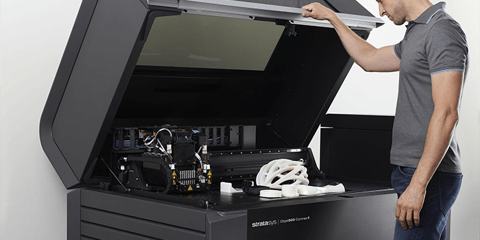
SLS (selective laser sintering) produces parts with high accuracy and can print designs with complex geometry. A laser selectively sinters powder one layer at a time to form a solid part.
HP’s Multi-Jet Fusion ( MJF) is similar to SLS, in that they both use heated build chambers, are powder-based and can produce parts with high accuracy using production-grade powders. The biggest difference between the two technologies is that MJF uses a solution to bind the powder and a heat lamp to cure the powder layer by layer.
To restrict the likelihood of parts warping or shrinking during printing, MJF and SLS printers use heated build chambers that heat up the powder to just below the sintering temperature.
MJF and SLS parts do not need to be anchored to the build plate and are suspended in the powder during the build. The heated powder allows for slower temperature changes and aids in dimensional accuracy. This results in temperature gradients in large SLS and MJF parts where the bottom of the part has cooled while the recently printed top layers remain at an elevated temperature. To further mitigate the likelihood of warping occurring parts are left in the powder to cool slowly (often for 50% of the total build time).
Finer points for dimensional accuracy of SLS/MJF
| Parameter | Finer detail |
| ---------- | ---------- |
| Dimensional tolerance | ± 0.3% (lower limit: ± 0.3 mm) |
| Shrinkage/warping | Shrinkage usually occurs in the 2 - 3% range however most SLS and MJF print providers allow for this in the design.|
| Support requirements | Not required. |
Curious about the cost and material options for SLS and MJF 3D printing?
Our SLS 3D printing services Our MJF 3D printing services Get a free, instant quote
Ready to transform your CAD file into a custom part? Upload your designs for a free, instant quote.
Get an instant quoteClarity, Accuracy & Tolerances in 3D Printing
Just because your 3D printer says it has "high resolution" does not mean it will produce accurate or sharp prints.
Understanding the meaning of the terms precision, clarity, and tolerance is a prerequisite for achieving quality 3D printing results, regardless of industry. In this article, we will analyze what these terms mean in the context of 3D printing.
Webinar
Want to learn how to use 3D printing for design? Watch our webinar and learn about the stereolithography (SLA) 3D printing process, different types of materials, and tips from experts on how to optimize your printing process to make it as efficient as possible.
Watch the webinar now
Let's start with some definitions: what is the difference between precision, clarity and tolerance? For each term, we will use a target - a common example for understanding these concepts, helping to visualize them.
Precision determines how close the measured value is to the true value. In the target example, the true value is the bullseye. The closer you are to the bullseye, the more accurate your throw. In the world of 3D printing, the true value is the dimensions of your CAD model. To what extent does a product made on a 3D printer correspond to a digital model?
Clarity corresponds to measurement reproducibility - how consistent are your hits on the target? Clarity only measures this reproducibility. You can always hit the same spot, but it doesn't have to be the bullseye. In 3D printing, this ultimately leads to reliability. Are you sure that you will get the expected results for each model produced by your printer?
In engineering terms, "clarity" is used to measure the reproducibility of results. Applied to materials for 3D printing, “clear” can mean the ability to manufacture complex geometries. For example, Formlabs Gray Pro Resin and Rigid Resin resins have a high "green modulus", or modulus of elasticity, that can successfully print thin and intricate details.
What accuracy is required in this case? This is determined by tolerances , which you define. How much wiggle room do you have based on the purpose of the model? What is the allowable variability in the closeness of the measurements to the exact ones? It depends on the specifics of your project. For example, a component with a dynamic mechanical assembly needs tighter tolerances than a conventional plastic housing.
If you're specifying tolerance, you'll probably need precision as well, so let's assume we're measuring bullseye accuracy. Earlier we called the shots in the picture with the target on the right fuzzy.
But if you have wide tolerances, this may not be a problem. The shots are not as close to each other as they are on the target on the left, but if the acceptable range of sharpness is ±2.5 hoops, then you are not out of range.
As a rule, achieving and maintaining tighter tolerances entails higher production and quality control costs.
White Paper
Tolerance and fit are important concepts that engineers use to optimize mechanical functionality and manufacturing cost. Use this white paper when designing 3D printed workpieces or as a starting point when designing a fit between parts printed with Formlabs Tough Resin or Durable Resin.
Download white paper
There are many factors to consider when thinking about precision and clarity in 3D printing, but it's also important to get your needs right.
For example, a sharp but inaccurate 3D printer may be optimal for some applications. An inexpensive Fused Deposition Modeling (FDM) machine will produce less accurate parts, but for a teacher teaching students 3D printing for the first time, the exact fit of the student's CAD model doesn't matter as much.
But if the printer performs to specifications and delivers the quality expected of it within the tolerances the user is accustomed to, this may be sufficient for successful operation.
Check out our detailed guide comparing FDM vs. SLA 3D printers to see how they differ in terms of print quality, materials, application, workflow, speed, cost, and more.
There are four main factors that affect the accuracy and clarity of a 3D printer:
3D printing is a type of additive manufacturing where models are made layer by layer. Violations can potentially occur in every layer. The layering process affects the level of clarity (or reproducibility) of each layer's accuracy. For example, when printing on an FDM printer, layers are formed using a nozzle, which cannot provide the same accuracy for obtaining complex parts as other 3D printing technologies.
Because layers are extruded, FDM models often show layer lines and inaccuracies around complex features. (Left is an FDM printed part, right is a SLA printed part.)
In stereolithography (SLA) 3D printing, each layer is formed by curing a liquid polymer with a high-precision laser, resulting in more detailed models and achieve high quality on a consistent basis.
Selective Laser Sintering (SLS) also uses a laser to accurately convert nylon powder into lightweight, durable parts.
The specifications of a 3D printer alone do not give an idea of the accuracy of the models produced. One of the common misconceptions about the accuracy of various 3D printing technologies is describing XY resolution as dimensional accuracy.
For digital light processing (DLP) printers, the XY resolution corresponds to the projected pixel size. Many 3D printer systems use this projected pixel size, or XY resolution, as a general measure of accuracy, such as stating that with a projected pixel size of 75 µm, the accuracy of the device is ±75 µm.
Check out our guide to SLA and DLP 3D printing, where we talk about the features of the two processes and how they differ.
But this data does not affect the accuracy of the printed model. There are many other sources of error that affect accuracy, from components and calibration to materials and post-processing. We will consider the last two factors in more detail.
The best way to evaluate a 3D printer is to study the models printed on it.
Accuracy may also vary depending on the media you are printing on and the mechanical properties of those media, which can also affect the likelihood of model warping.
Formlabs Rigid Resin has a high "green modulus", or modulus of elasticity before final polymerization, which allows you to print very thin models with high definition and reliability.
But, again, it all depends on your goals. For example, in dentistry, the accuracy of 3D printed models is critical. But if you're printing a concept model, chances are you just want to get a general idea of the physical product, and accuracy won't be that important.
Margins, mold surfaces, and contact surfaces printed with Formlabs Model Resin are accurate to within ±35 µm of the digital model at over 80% of surface points when printed at 25 µm settings. The overall accuracy across the entire arc is within ±100 µm on 80% of surfaces when printed with settings of 25 or 50 µm.
3D printed models often need to be cured, which in turn often leads to shrinkage. This is normal for any part made using SLA or DLP 3D printing. Depending on the printer, this phenomenon may need to be considered in the design. PreForm, Formlabs' free file preparation software, automatically compensates for this shrinkage, ensuring that the final cured models are the same dimensions as the original CAD model.
How does the final polymerization work? Learn more about the theory behind the process and see efficient ways to successfully finish curing models made with stereolithographic 3D printers.
Producing quality models on a 3D printer requires attention not only to the printer itself, but to the entire production process.
The final result may be affected by the print preparation software, post-processing materials and tools used. In general, integrated systems designed to work together produce more reliable results.
Unlike machining, where parts are progressively improved to tighter tolerances, 3D printing has only one automated manufacturing step. While complex coating adds cost to processes such as CNC milling, creating complex features with 3D printing is essentially free, although the tolerances of a 3D printed model cannot be automatically improved beyond the capabilities of the printer. without resorting to subtractive methods.
3D printing is a great option if you have rough, complex features such as undercuts and complex surfaces, and don't necessarily need surface accuracy better than ±0.125mm (standard machining). Tolerances beyond standard machining must be achieved using subtractive methods, either through manual or machine processing, for both 3D printed and CNC models.
SLA has the highest tolerance compared to other commercial 3D printing technologies. The tolerances for stereolithographic 3D printing are somewhere between standard and precision machining.
In general, more malleable stereolithography materials will have a wider tolerance zone than more rigid materials. Designing subassembly parts for tolerance and fit reduces post-processing time and simplifies assembly, as well as reduces material costs per iteration.
There are many other factors to consider when evaluating 3D printers. Should your models be isotropic? What mechanical properties should your models (and, accordingly, the materials from which they are made) have? The best place to start is to get familiar with the physical models printed on a 3D printer. Order a free material sample from Formlabs of your choice and see for yourself the quality of your stereolithography print.
Request a sample 3D model
What is the actual size of the product after 3D printing?
05/10/2018 in 3D Modeling, Expert Blog, Instructions
In this article, we will consider the most common reasons for changing the final dimensions of manufactured products printed on a 3D printer. This article will be helpful for designers and inventors to understand how to design 3D models for 3D printing.
First, let's introduce some terminology. All deviations that occur in the technological process of 3D printing and related technologies, we will call “error”. Consider what types of errors are and delve into each of them.
- Extrusion width error.
- Approximation of radii depending on layer height.
- 3D printer extruder positioning accuracy.
- Inertial beats.
- Uncontrolled material shrinkage.
- First layer error.
- Porosity.
- Matching accuracy after printing details, splitting into components.
- Locations where support material has been torn off.
- Thin wall roughness.
Extrusion width error.
Preparing a 3D model for 3D printing comes down to creating a so-called G-code. G-code is a computer code that sets the movement for all the electric motors of a 3D printer. These motors include those responsible for moving the extruder (the 3D printer's 3D printed head). The movements and movements of the extruder are given by the trajectory, which is determined by the line. In preparation for 3D printing, the model is split along the Z axis into layers, determined by the selected layer height. The trajectory of the extruder is built based on the dimensions of these layers, and in the case of the layer perimeter, it describes the outer surface of the model, averaged along the Z axis. In turn, the extruder repeats the trajectory laid down in the G-code, namely the center of the nozzle. Ultimately, when designing models, it is necessary to take into account the fact that the nozzle itself has a hole diameter through which plastic is extruded. In simple terms, the nozzle radius is added to the size of the 3D model. When choosing a 3D printer, in terms of extrusion width error, the accuracy of the part will be higher on the one with a smaller diameter nozzle.
 And when designing three-dimensional models for 3D printing, it is necessary to lay a margin for model widening. I want to note that in other 3D printing technologies that use a laser or an illumination device, the width of the outer perimeter line depends on the focus, that is, on the thickness of the beam. As a rule, these parameters can be clarified with the manufacturer of the 3D printer or with Studia3D specialists.
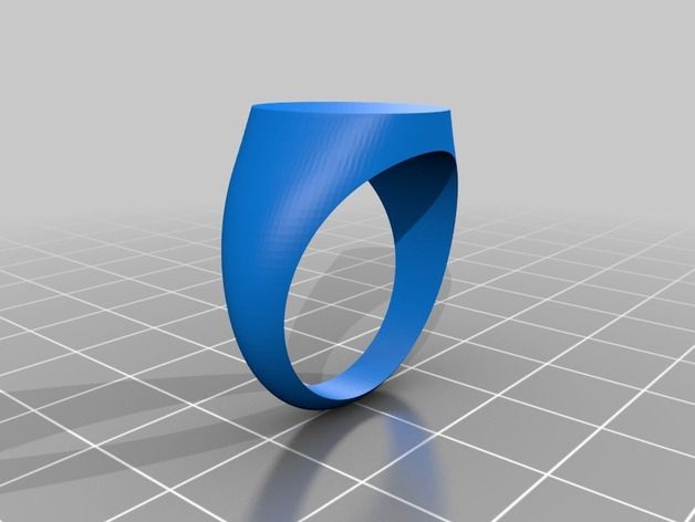
Let's see how it works on the example of a 3D model that has a hole.
The figure shows the 3D model, rendering of the prepared G-code and the trajectory of the center of the extruder nozzle for the 7th layer of 3D printing. Select the perimeters of the holes and overlay the actual extrusion width on the trajectory (Highlighted in light green).
As you can see, the hole diameter is smaller. How much? On the nozzle radius on one side + the nozzle radius on the other. That is, when designing a hole, I need to lay a gap equal to the width of the nozzle. The same goes for all other cars. The smaller the nozzle size, the closer to the nominal dimensions the part will be. At the same time, printing with a nozzle of a smaller diameter will cost more. This is due to performance. Through a larger nozzle, more plastic comes out per unit time, which affects the speed of printing. The operating time of the printer, as well as the amount of material, affects the cost of obtaining the product.
Approximation of radii depending on layer height.
The specified layer height directly affects the accuracy of 3D printing. This is clearly expressed on the radii in the sections of the model along the vertical. Consider the part from the previous paragraph, positioning it on the edge in the 3D printer chamber.
As you can see in the figure, the quality of the hole depends on the selected layer height. The lower the layer height, the better the detail. In this case, it is worth considering the time of 3D printing. As the layer height increases, the print time decreases by reducing the total length of the trajectory described by the extruder. Accordingly, the price of the part is reduced, because. The operating time of a 3D printer directly affects the cost of 3D printing.
3D printer extruder positioning accuracy.
This parameter determines the accuracy of repetition by the center of the extruder nozzle of the trajectory specified in the G-code. In other words, this parameter characterizes the maximum possible deviation of the center of the extruder nozzle from the trajectory during printing. This parameter is specified by the 3D printer manufacturer for a specific printer model. But it should be noted that this parameter corresponds to the manufacturer's recommended 3D printing speed. In turn, Studia3D specialists, when preparing the G-code, reduce the influence of this parameter to a minimum, but do not exclude it at all. In addition to speed, this parameter is affected by the rigidity of the 3D printer and the extruder drive system.
Inertial beats.
As a special case of positioning accuracy, we single out inertial beats that occur during 3D printing as a separate point. This parameter is affected by the same positions that were described in the previous paragraph, however, this error is reduced in a different way. This can be understood by studying the moment at which the influence of this error on the print quality arises - a sharp change in the direction of the extruder's motion vector. When the electric motors, together with the drive system, abruptly change the direction of the trajectory, the print head, which has some characteristic weight, continues to move in the previous direction by inertia. As a result, dynamic damped oscillations occur, which negatively reflects the surface. The influence of this error is reduced in two ways. Decreasing the speed of printing the outer perimeter, which we use when printing all models without exception and is laid at the stage of preparing the G-code. The second method is laid down when designing the model: if possible, it is necessary to add mates to acute-angled faces in the model, which, when the part is positioned on the 3D printer platform, in sections parallel to the XY plane, will give sharp corners in the perimeters.
 As practice shows, a pairing of 2 mm is considered sufficient. We show with an example.
As you can see in the figure, by rounding the corner (by entering a fillet on the face), we minimized the influence of this error.
Uncontrolled material shrinkage.
This parameter has its effect, as a rule, in the case of 3D printing of large objects. Large - this means more than 30% of the maximum size of the 3D printer camera along any of the coordinate axes. Most often, this error manifests itself in interlayer adhesion and a decrease in dimensions in planes parallel to XY.
Our observations have shown an approximate shrinkage for some of the most common materials in relation to cross-sectional dimensions parallel to the coordinate axes.
ABS: XY ≈ 5%; Z ≈ 1%
PLA: XY ≈ 2%; Z ≈ 0.5%
Polypropylene: XY ≈ 7%; by Z ≈ 10%
First layer error.
The G-code preparation program considers the 3D printer platform to be absolutely parallel to the XY plane, however, in practice, platform calibration also has its own error. In Studia3D, the norm for the difference in thickness of the first layer is:
Δ=0.1 mm from a layer height of 0.2 mm
Δ=0.05 mm from a layer height of up to 0.2 mm
Porosity.
Porosity in the case of 3D printing is usually discussed only in the case of filling percentage of internal floors up to 100%. However, when printing with 100% infill, the porosity does not go anywhere.
This can be clearly seen by examining the gap in the workpiece through a microscope to determine the strength characteristics.
If the model is not included in the printable area of the 3D printer, it is split into components. In the best case, grooves are provided for the most accurate assembly. You need to understand that the assembly of the model from the components also affects the accuracy of the overall design. This accuracy is very difficult to assess. We accept deviations from the given model of the order of + - 2%. To fix the joint, we almost never use glue, but use a special chemical solution. Ultimately, the parts are not glued, but soldered, only not by thermal melting of the material, but by chemical. As for the adhesion strength: it is higher than the adhesion between layers. In simple terms, if you throw such a part against a wall, it will break, but first of all not at the joints.
Locations where support material has been torn off.
This item applies to mechanically removed supports. Since the material of the support and the material of the main part consist of the same material, they are simply soldered together under the influence of temperature. When such supports are torn off, traces, threads, chips, etc. remain.
To minimize this error, it is necessary to order 3D printing with soluble supports. Due to the expensive soluble support material, the cost of 3D printing also increases significantly. Accuracy, like beauty, requires sacrifice.
Thin wall roughness.
When preparing a standard G-code, the program strives to make your part as strong as possible. This is bad only in one case, when the product has thin-walled elements. When constructing a trajectory, we set the minimum wall thickness inside which the infill will be built. As a rule, this thickness is equal to the 3rd nozzle diameter. But in cases where there are places where the thickness is less than the thickness of the outer wall, when constructing the trajectory, the program will draw one perimeter on each side, and fill the void between them. Due to the fact that filling will occur at a distance of 1 to 2 nozzle diameters, the extruder will begin to vibrate, inertial beat will begin (see point inertial runout ). The more this distance is reduced to 1 nozzle diameter, the faster the near-resonant frequency occurs. All this negatively affects the appearance of this wall, since the vibration is transmitted to the adjacent material. Let's look clearly.
To minimize this error, it is necessary to design the part in such a way that the wall thickness is a multiple of the nozzle diameter.