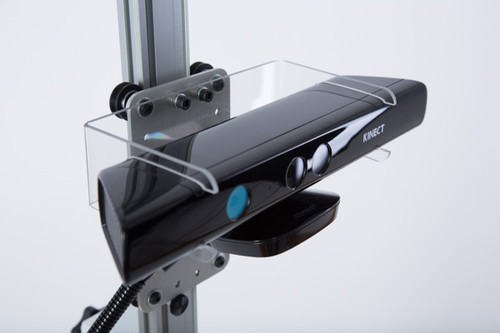
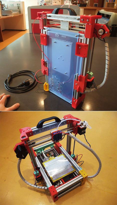
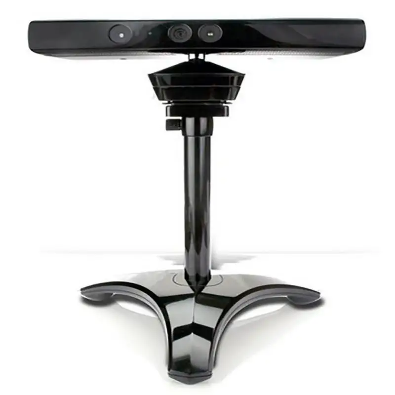
Xbox one kinect sensor 3d scanner
Xbox One Kinect and 3D Scanning - Scanning - Talk Manufacturing
iTech4DP
#1
Just thought I would throw this out there for any DIY’ers. I just hooked up the Xbox One Kinect to the PC and got the Microsoft 3D scan app, and it worked fantastic! I just did a few test shots to see how the depth worked out from one side and so far it’s pretty decent. I picked up the Kinect sensor used for $125CAD and the adapter for $65CAD. The software is free from the Microsoft Store, so this is a really cheap 3D scan option. The app exports the completed file in either .STL or.OBJ. Alternatively, you can download the Kinect SDK pack from Microsoft and build the .STL from raw footage.
8 Likes
3dpGeek
#2
I used to do this with windows 8 but after the release of windows 10 that feature went away. What version of Windows do you run?
iTech4DP
#3
I’m running it on Windows 10. Looks like the 3D Scan and Design app are new as of this month though.
3dpGeek
#4
Oh sweet! The “Windows Builder” has been around I’ll have to check the scanning now!
Richard_20
#5
What adapter do you need for this?
Richard_20
#6
Will it work for windows7?
3dpGeek
#7
There is a Microsoft AC Adapter for $50 though Microsoft Store
iTech4DP
#8
I know that the app won’t work on Windows 7 nor will the Kinect SDK v2.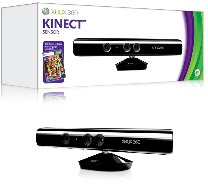 0, but Kinect SDK 1.6+ plus might just work. It’s worth a shot.
iTech4DP
#9
This is the adapter I purchased for mine. Microsoft 9J7-00001 Kinect Adapter For Windows . Since the Canadian dollar sucks so bad right now it was $65 for me.
Richard_20
#10
Sweet I have the adapter that came with the Kinex already, just need the software to run it
Piet3r
#11
Apparently you also need quite a high-end PC for this? Can you tell us the specs of your PC?
Richard_20
#12
Windows 8 Lenovo icore4 or 5 something like that…
iTech4DP
#13
Really? I use an MSI laptop core i7, 8GB ram and it works great.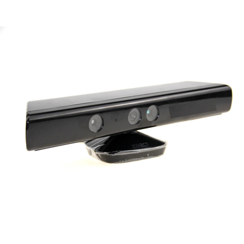 I read that an nvidia chipset helps too.
l2smith3
#14
The xbox one kinect requires a very specific Intel chipset driving your USB 3.0 port. Something Microsoft fail to mention clearly in the adaptor requirements. Also 64 bit win 8.1 or higher. There is a very hard to find app from microsoft that will check your PC for compatibility but its well hidden. A lot of the very expensive software for the original kinect work poorly if at all and have terrible support.
iTech4DP
#15
Well that sure sounds like a bit of bad luck, yes you do need a 64 bit processor to run the Kinect SDK v2.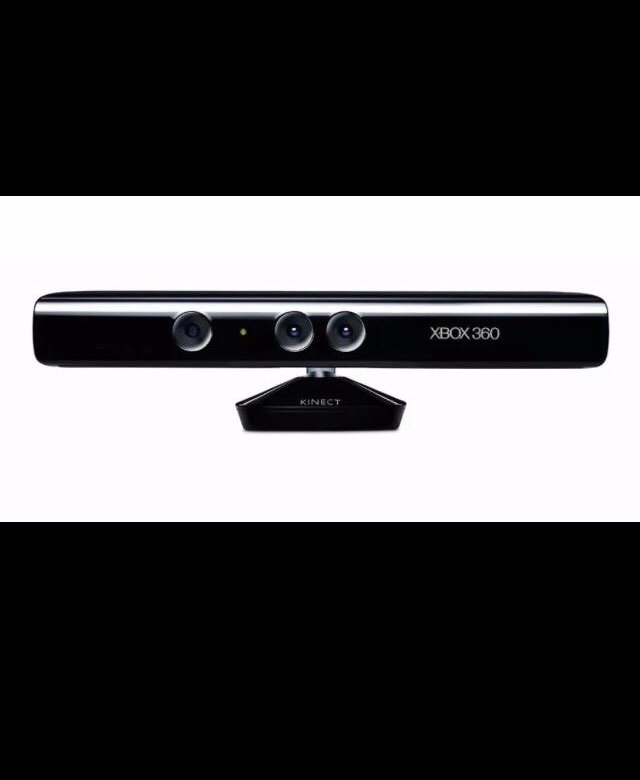 0 and the 3D Scan and Design App. USB 3.0 port is necessary as well. The results are very fluid so far for me, much better than the alternative DIY scanners out there. The Microsoft 3D scan app looks to be brand new, in the last month or so.
Here is a link to the support page for it:
https://msdn.microsoft.com/en-us/windows/hardware/mt593367
totof1965
#16
Tried this but can’t have a good scan rate, maybe I need more light ?
Geoffrey_2
#17
Actually, if you get a kinect v1, the previous model, it´s work as well with pretty much the same quality even if the scanning time is longer.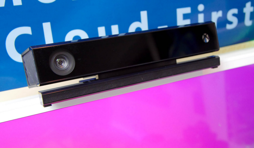 Otherwise, it work with USB 2.0, windows 7 and 32/64bits computer. The kinect v1 is also quite cheap if you succeed to get one on second hand. So it a worth to try. Keep in mind than photogrammetry is also a good alternative. In both case, keep in mind that the model should stay still during the scanning process.
Geoffrey_2
#18
I am not quite sure about the Kinect v2 but the Kinect v1 work with infrared light so you could scan even in the dark. Of course, you will get only the surface not the texture. But in 3D printing, except in you have color 3D printer, the texture of the model doesn´t matter.
monkeymake_xyz
#19
I’ve been getting fun results with my Kinect 360.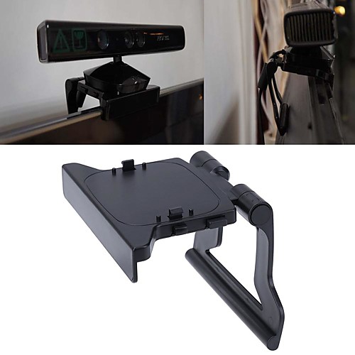 I am struggling to get busts done properly at the moment but having fun with it.
Theres handles on Thingiverse but I don’t have the link close to hand. Have attached a pic of both a test print of my daughter and the handle I’ve done.
1 Like
iTech4DP
#20
Cool! Nice handle!
I was already wondering how I can make this a little more portable. Right now it’s fairly bulky to carry around an object, but it works pretty decent if I keep it stationary.
next page →
Microsoft Integrates Kinect into 3D Builder, Allowing Full Body Color 3D Scanning and Printing - 3DPrint.com
It’s certainly no surprise that Microsoft finally dipped their feet into the water with 3D printing technology. They developed their 3D Builder app about a year ago, with a product that allows you to 3D print with ease, whether you are downloading designs or creating something new and original.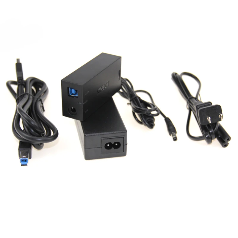
Available at the Windows Store, 3D Builder allows you to load, view, manipulate, and print 3D from your PC running Windows 8.1. But wait! There’s a one-two punch going on with 3D Builder: now you can get really innovative and original with creations due to Microsoft’s innovation of Kinect for Windows v2 sensor into 3D Builder, allowing you to perform DIY full body color scanning.
Novices can scan and print items in full color with the capabilities of 3D Builder and Kinect. For example, if you are having yourself scanned, you would need someone else to do the scanning, which is very user-friendly. You just have to stand very still while being scanned by the Windows Kinect, and quickly you will see yourself in the 3D Builder app, where you can refine the image and then send it to be 3D printed.
3D Builder allows you to:
- Scan in 3D color using a Kinect for Windows v2 sensor.
- Refine and repair models automatically before printing.
- Automatically repair models to make them printable.

- Print directly to your 3D printer or order your model through 3D Systems.
- Emboss any model with text or images.
- Merge, intersect, or subtract objects from each other, or slice them into pieces.
While we are most excited and focused on the Kinect integration with 3D Builder that allows you to scan yourself and your friends, with the update, Kinect Software Development Kit 2.0, Microsoft offers over 200 new functions to make Kinect more user-friendly and accessible, with developers able to make their Kinect apps available in the Windows Store, including:
- 3D Builder
- Nayi Disha – interactive childhood education apps
- YAKiT – a 2D/3D character design app
‘This was a frequent request from the community and we are delighted to enable you to bring more personal computing experiences that feature gesture control, body tracking, and object recognition to Windows customers around the world. Access to the Windows Store opens a whole new marketplace for business and consumer experiences.
,” said Microsoft officials, regarding accessibility of Kinect-integrated apps into the Windows Store.
Microsoft does recommend that you run 3D Builder with a Kinect for Windows v2 sensor for better results.
Everything is free to download, except for the Kinect adapter to hook up your Xbox One Kinect to your PC, through a USB 3.0 port. Available for $49.99, the adapter should be available to you anywhere.
The new Kinect Adapter for Windows also requires a USB 3.0 port, is priced at $199, and won’t work with the Kinect sensor for Xbox 360.The Kinect for Windows software development kit (SDK) 2.0 is available today for free download. There are no fees for runtime licenses of commercial applications developed with the SDK.
Slice objects in 3D Builder
Have you been using 3D Builder? Share your thoughts and experiences with us in the Microsoft Integrates Kinect into 3D Builder forum at 3DPB.com.
Stay up-to-date on all the latest news from the 3D printing industry and receive information and offers from third party vendors.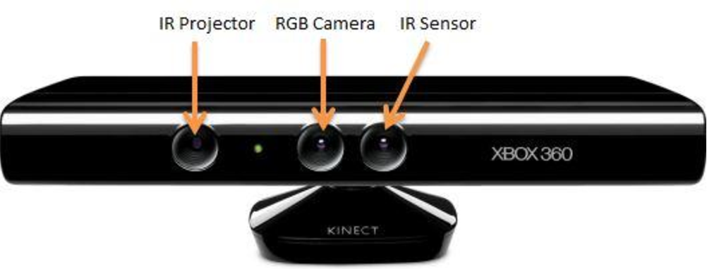
Tagged with: 3d builder • 3d builder app • kinect • kinect for windows • microsoft • windows store
Please enable JavaScript to view the comments powered by Disqus.
Testing and validation of the latest Kinect-based device for 3D scanning of the plantar surface of the foot under load.
Testing and validation of the latest Kinect-based device for 3D scanning of the plantar surface of the foot under load.
- Julia Rogaty,
- Alberto Leardini,
- Maurizio Ortolani
- Paolo Caravaggi
Journal of Foot and Ankle Research Chapter 12, article number: 46 (2019)
Excerpt
Background
The development of additive technologies, along with new 3d scanning devices, is rapidly filling the technology market with custom devices for personalized medicine. In podiatry and the shoe industry, the implementation of orthopedic practice and the development of shoe models requires taking into account foot pathologies or morphological changes that cannot be detected using standard devices. Laser scanning is the gold standard for obtaining a digital 3d model of the shape of the foot. Due to its cost, laser scanning is not as widespread and used. Therefore, the casting method is still used today. The purpose of this study is to develop and validate a novel 3D scanning device based on Microsoft's Kinect sensor technology, which can take a scanned image of the plantar part of the foot under load.
Methods
A study was conducted on 14 healthy patients who had never had a foot or lower limb injury and had no symptoms of injury to determine the measurement accuracy and repeatability of the foot scanner prototype. Accuracy is determined by comparing Kinect-based scanned images with high-resolution images obtained using a laser scanner. The repeatability of the results is demonstrated by comparing scanned images of the same part of the foot in different sessions.
Results
The total mean square error (RMS) of the Kinect scanner was found to be less than 3 mm for the entire plantar surface of the foot, and less than 1. 6 mm for the arch of the left and right foot. The stable index of the SCP of the repeatability of the results of pairwise comparison in different scanning sessions turned out to be 1.2 ± 0.4 mm.
Conclusions
This 3d Kinect scanner has demonstrated optimal intra-operator repeatability and its accuracy has been determined to be adequate for producing 3d scanned images of the plantar surface of the foot. All of the above correspond to various clinical applications. The device is a worthy, affordable alternative to measuring foot parameters in automatic mode to an expensive laser scanner. The method of developing insoles and shoes is greatly simplified.
Peer Review Reports Available
Basic Information
There is growing interest in the research and development of new 3d scanning and modeling devices for body parts. Now it is appropriate to state the existing requirements for orthopedic devices and shoes [1]. Both in podiatry and in the footwear industry, exact geometric characteristics of the shape of the foot are required.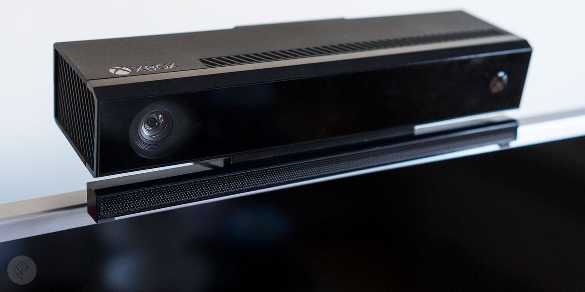 Such data are critical for the development of orthopedic devices and footwear models for different categories of people from healthcare workers [2, 3] and athletes [4] to patients with diabetes [6, 7] or with diseases of the foot and lower extremities [5 ]. The longitudinal arch of the foot is the most common morphological feature used to characterize the type of foot [8, 9]. The foot acts as a spring: when the load is distributed vertically, energy is stored in various viscoelastic regions. The plantar aponeurosis disease can be restored only by elastic recoil [10]. The form of the foot, which is mechanically affected by shoes or orthotics, is revealed under load conditions, when the joints of the foot and soft tissues involved around the medial-longitudinal arch are deformed under the weight of the body and in contact with the surface. It is widely known that a significant reduction in peak pressure can be achieved using the usual orthopedic apparatus without additional load [11] or removable insoles [12, 13].
 However, using the traditional casting method, it is not always possible to obtain a model of the foot under load. This method does not perform automatic measurements [14], and also produces the least accurate results compared to the digital scanning method [15, 16]. In this regard, laser scanners or profiler beam scanners are the gold standard for capturing high resolution spatial 3d scans of the foot. In scanners with profiling beam technology, the light beam is directed to the surface of the foot, and cameras located in different positions detect the curvature [17]. Laser scanners have a radiation source that directs a laser beam at the foot, then picks up the reflection with one or more sensors. Both scanners reconstruct the 3d model of the foot using the triangulation method.
Although, 3d scanners are significantly more profitable from an economic point of view compared to the cost of plaster casting [18, 19], however, their cost is much higher (6000-15000 euros), thereby reducing their use and prevalence. Thus, the Kinect scanner with a sensitive RGB camera developed by Microsoft for the video game industry is a possible, cost-effective solution for performing 3D scanning of the shape of the foot. The sensor is used as a static body scanner, for example, when detecting problems with posture [20], spinal deformity [21], and also as a device for motion analysis [22,23,24,25,26]. Until now, Kinect technology has been used to obtain data on the position of the foot and its morphology [27,28,29]. Research into the 3d foot scanner is still ongoing.
The aim of this study is to confirm the accuracy and repeatability of the latest 3D foot scanner device based on Microsoft's low-cost Kinect technology to determine the exact surface of the foot under load.
Methods
The Kinect Sensor is a sensitive RGB camera developed by Microsoft (Redmond, USA) that captures uniform depth, then colors the area around the foot in the image [https://developer.microsoft.com/en- us/windows/kinect. Accessed 15 Mar 2019.">30]. Initially, the technology was developed to improve the Xbox 360 game console. Kinect sensors have long been used not only in the gaming industry. The creation of the MS Windows-based software development kit for your own applications contributed to the development of this process. The 2012 Kinect Foot Scanner for Windows was tested for accuracy and repeatability in this study. out of a maximum of 30 steps. The scanner is an 82 cm high wooden box with a scanning glass plate on top and a Kinect sensor on the bottom (Fig. 1a). The sensor is attached above a rotating plate, the operation of which is not automated during scanning. the plantar aspect of the foot can be seen at different angles, while maintaining a focal length of 55 cm. The scanning dish is a glass surface with dimensions of 40 × 35 × 1.5 cm, using which you can view the surface of the plantar part of the foot. Depth sensors are also involved in the measurement process. In order to minimize light reflection, the wooden box is painted black.
 Thus, light from external sources during scanning is limited. Scan time is 25 seconds. During this time, the sensor has time to rotate 360 °. The Skanect software for Windows (Skanect from Occipital, version 1.8) is used to acquire and post-process 3d scanned images in raw format with the acquired depth data (Fig. 1b). The laptop (Intel Core i5 6300 HQ @2.30 GHz, 12GHz RAM) used for data collection allows you to get high quality 3d scanned images up to 21 steps.
Fig.1
a) 3d Kinect foot scanner. The Kinect sensor is located on a rotating platform at the very bottom of the wooden box. On top is a 15 mm thick glass plate that can be used to scan the plantar surface of the foot under different loading conditions. b) dot 3d models of the plantar part of the foot in the standing position, obtained using the computer program "Skanect".
Fourteen healthy volunteers (aged 21 to 61 years; BW 23±3 kg/m²; EU shoe size 37-43) took part in the study, with no medical history and no symptoms of foot or limb injury.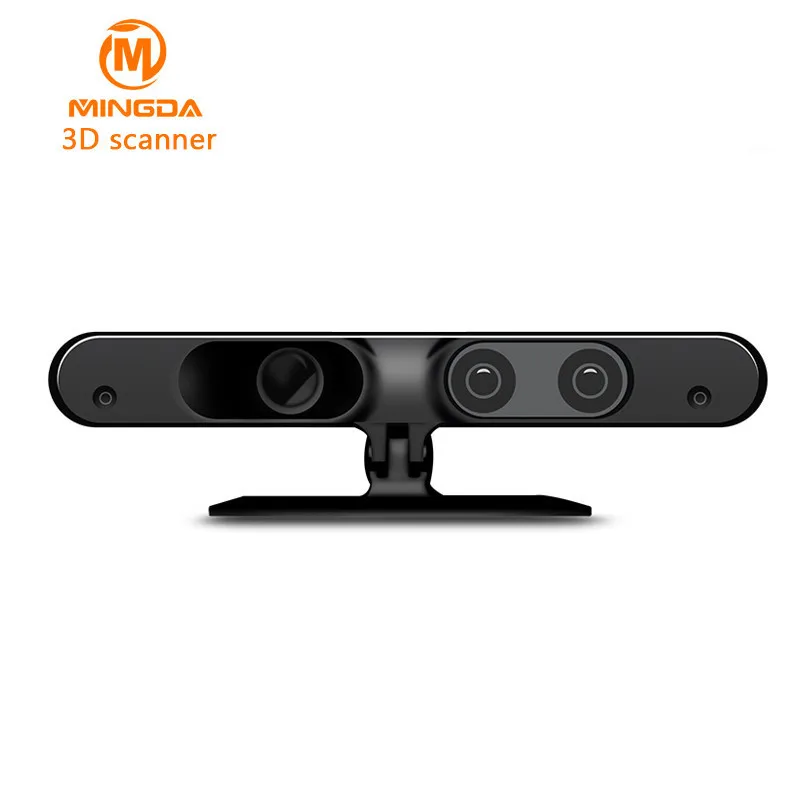 According to the data obtained, all subjects underwent podoscopy foot measurement. Some showed a mild form of flat feet ( n = 5), flattened foot ( n = 6) and mild overpronated (valgus) foot ( n = 3). A box made of organic glass for measuring the parameters of the foot is used to obtain their main morphological characteristics (Fig. 2). The accuracy of the device was measured by comparing simple scanned images of 28 feet of 14 subjects with high resolution images obtained with a 3d foot scanner (i-Qube, Delcam, CK). Scanned images were taken in a standing position of two feet and with full load; this position was chosen over the other loading conditions due to its frequent occurrence. Thus, the absence of differences in the shape of the foot is guaranteed. Using the Geomagic Control™ 3d modeling program (3D Systems, Rock Hill, USA), spatial alignment was performed and the average difference between the Kinect- and i-Qube-scanning sessions was calculated. Alignment was achieved using the "Best match to alignment" procedure - a preliminary procedure implemented by measuring 5000 randomly selected points on the image.
 More accurate data can be obtained by measuring 25,000 random points until the random difference between images is minimized [32]. Distance maps, i.e. point graphical representation of the distance between two 3d datasets, taking into account the root mean square error, is used to measure the accuracy of Kinect-scanned images of the entire plantar surface, as well as the middle arch area. The latter is independently measurable due to conformity with the classification of the type of foot, as well as the influence on the development of models of orthopedic shoes.
Fig. 2
The PodoBox is a plexiglass device designed to measure the foot. Adhesive lines on the side and bottom of the device are used to measure the height and length of the arch ( a ), and transparent flexible rulers are used to measure the length and width of the foot ( to ).
Repeatability of Kinect scans across sessions was estimated based on data from 28 subjects.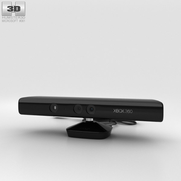 The foot of each subject was scanned in three sessions with a frequency of several days. A pairwise comparison was made to measure the root mean square error between scanned images of the same foot. The RMS score was calculated for both the right and left feet of each subject - session #1 compared to session #2, session #1 compared to session #3, session #2 compared to session #3 - and measured using the average. The coefficient of variation of the standard error throughout the study was measured to determine the repeatability of the results on the scans.
In the case of measuring the effectiveness of the scanner in determining the differences between types of feet, the main morphological parameters of three types of foot diseases were obtained - two feet with flat feet, two with flattening and two more with hyperpronation (Fig. 3). Specialized software "Matlab" (MathWorks, R2016a) has been developed for automatic analysis of Kinect-scanned images of the foot. With this program, you can measure foot length, foot width, arch height, arch width, and arch index. Arch width refers to the maximum depth of penetration of the arch of the foot in the medial-lateral direction, expressed as a percentage of the width of the foot in the same position. The arch index is calculated by rotation between the area of the middle and third parts of the footprint and the full area of the footprint without toes [33]. Moreover, various measurements of foot length and width obtained using the PodoBox device are compared with the same results obtained using a 3d scanning program and the average percentage of error is calculated.
Fig.3
Scanned samples of flat feet ( a ), flat feet ( b ) and valgus ( c ) in standing position. Top view - under the podoscope; bottom - according to Kinect images obtained by the Geomagic program.
Results
Kinect Scan Accuracy
The accuracy of 3d Kinect images of the arch area was higher than the accuracy of the entire surface of the foot.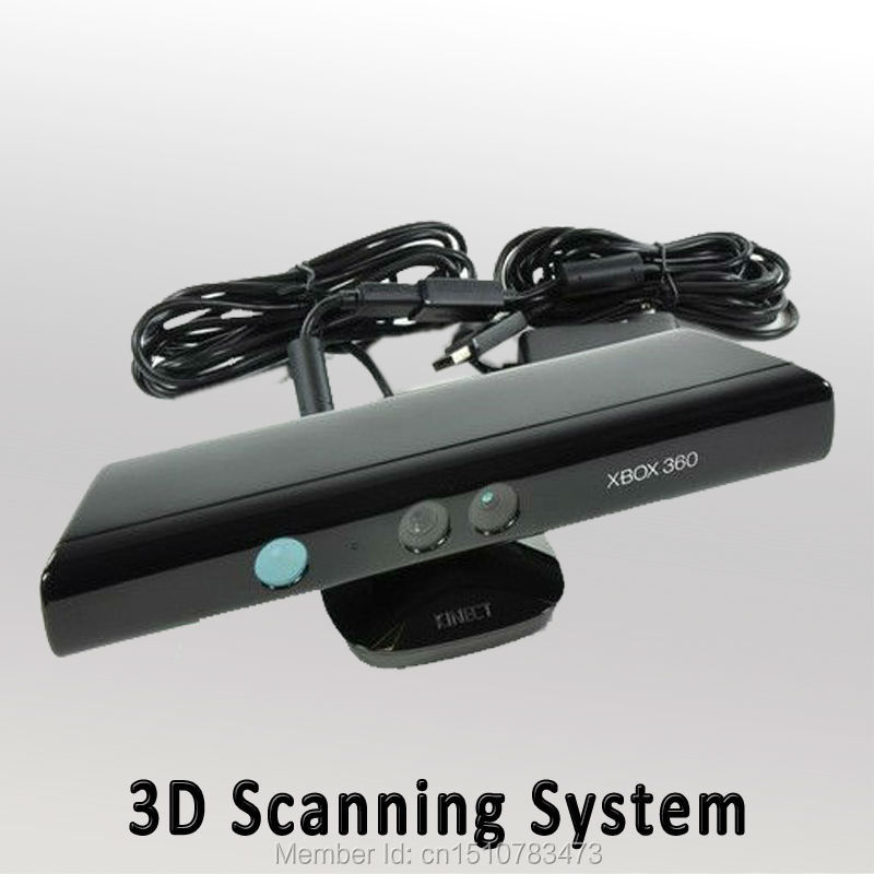 Comparing 3d Kinect scans with scans made using a high-resolution laser device (Fig. 4, top), an RMS error of 2.8 ± 0.6 mm and 2.9±0.4 mm, respectively, left and right foot. The corresponding errors only in the arch area were (Fig. 4, bottom) 1.4±0.4 mm and 1.6±0.5 mm (Table 1).
Fig.4
Comparative color distances [mm] of the laser scanner with the Kinect scanner of the right foot of one subject under load, according to the "Best Fit Alignment" software "Geomagic: Best Fit Alignment". Above are errors on the entire plantar area; below - errors in the arched area.
Table 1. Root mean square error [mm] between K and nect-scan values and reference templates for each left and right foot of 14 subjects. The overall mean square error can be seen at the bottom of the table.
| Subject ID | RMSE [mm] | |||
|---|---|---|---|---|
| Left foot whole plantar surface | Right foot whole plantar surface | Left foot arch region | Right foot arch region | |
| Subj 01 | 2.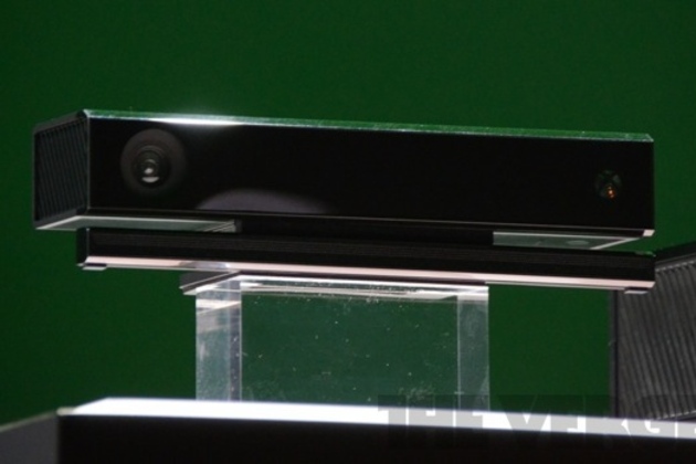 8 8 | 3.8 | 1.8 | 1.6 |
| Subj 02 | 2.2 | 2.6 | 1.5 | 2.3 |
| Subj 03 | 2.8 | 3.2 | 1.8 | 0.7 |
| Subj 04 | 3.3 | 2.7 | 0.7 | 0.9 |
| Subj 05 | 3.5 | 2.9 | 1.5 | 2.0 |
| Subj 06 | 2.3 | 2.2 | 1.6 | 1.8 |
| Subj 07 | 2.9 | 3.6 | 1.3 | 1.3 |
| Subj 08 | 3.5 | 2.2 | 1.0 | 2.5 |
| Subj 09 | 2.7 | 3.5 | 1.5 | 1.2 |
| Subj 10 | 3.2 | 2.8 | 0.9 | 1.5 |
| Subj 11 | 1.6 | 1.9 | 1.1 | 1.1 |
| Subj 12 | 2.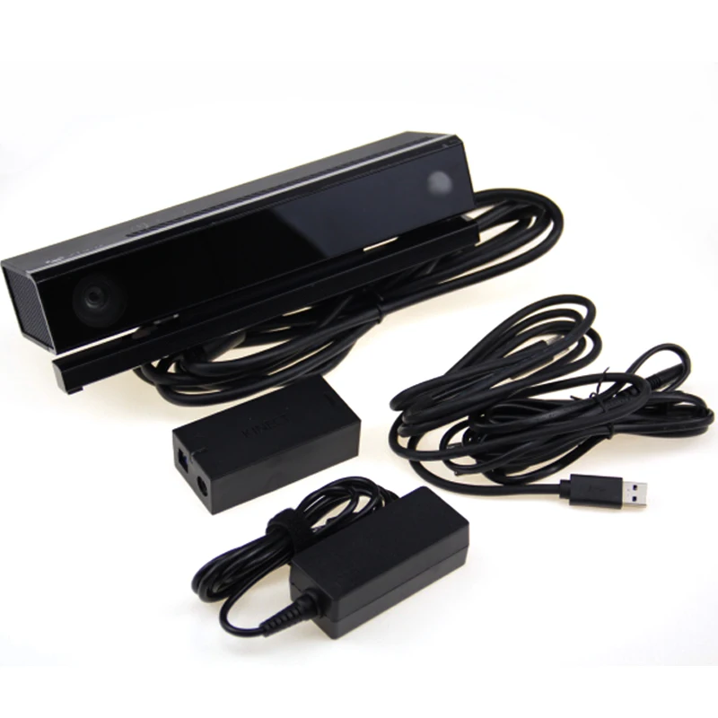 9 9 | 3.3 | 2.0 | 1.9 |
| Subj 13 | 2.5 | 3.7 | 1.4 | 1.5 |
| Subj 14 | 3.6 | 2.3 | 1.6 | 2.2 |
| Mean ± SD | 2.8 ± 0.6 | 2.9 ± 0.4 | 1.4 ± 0.4 | 1.6±0.5 |
Kinect scan match
Kinect scan match was good at all stages. The overall standard deviation of the pairwise comparison of images obtained in three sessions was 1.2±0.4 mm for both the left and right foot (Table 2). The average coefficient of variation was 24.3±12.3% and 17.4±10.5%, respectively, of the left and right foot.
Table 2. Root mean square error [mm] in distance is calculated by comparing three images taken from different scanning devices.
| Subject ID | RMSE [mm] - Left foot whole plantar surface | RMSE [mm] - Right foot whole plantar surface | ||||||
|---|---|---|---|---|---|---|---|---|
| trial1 vs trial2 | trial1 vs trial3 | trial2 vs trial3 | mean ± SD | trial1 vs trial2 | trial1 vs trial3 | trial2 vs trial3 | mean ± SD | |
| Subj 01 | 1.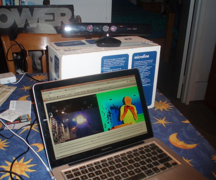 1 1 | 1.1 | 0.8 | 1.0 ± 0.2 | 1.2 | 1.4 | 1.1 | 1.2 ± 0.1 |
| Subj 02 | 1.3 | 1.4 | 0.7 | 1.1 ± 0.4 | 0.9 | 0.8 | 0.5 | 0.8 ± 0.2 |
| Subj 03 | 1.2 | 1.0 | 0.6 | 0.9 ± 0.3 | 1.4 | 1.4 | 1.5 | 1.4 ± 0.1 |
| Subj 04 | 1.6 | 1.6 | 0.8 | 1.3 ± 0.5 | 1.3 | 1.5 | 1.2 | 1.3 ± 0.2 |
| Subj 05 | 1.0 | 0.9 | 1.0 | 1.0 ± 0.0 | 0.8 | 0.8 | 0.5 | 0.7 ± 0.2 |
| Subj 06 | 1.3 | 1.8 | 1.0 | 1.3 ± 0.4 | 1.9 | 2.0 | 1.0 | 1.7 ± 0.5 |
| Subj 07 | 1.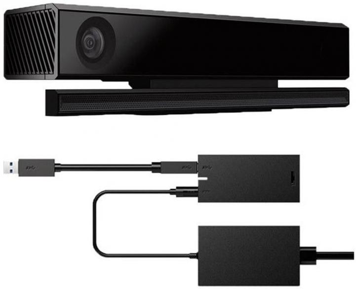 8 8 | 1.7 | 0.9 | 1.5 ± 0.5 | 1.8 | 1.6 | 0.9 | 1.4 ± 0.5 |
| Subj 08 | 0.9 | 1.0 | 1.3 | 1.1 ± 0.2 | 1.7 | 1.8 | 1.1 | 1.5 ± 0.4 |
| Subj 09 | 2.2 | 1.9 | 0.9 | 1.7 ± 0.7 | 1.2 | 1.1 | 1.0 | 1.1 ± 0.1 |
| Subj 10 | 1.2 | 1.3 | 1.1 | 1.2 ± 0.1 | 1.2 | 1.2 | 0.9 | 1.1 ± 0.1 |
| Subj 11 | 1.2 | 1.5 | 1.4 | 1.4 ± 0.2 | 1.3 | 1.3 | 1.2 | 1.0 ± 0.0 |
| Subj 12 | 0.9 | 0.6 | 0.7 | 0.7 ± 0.2 | 1.0 | 0.9 | 0.9 | 1.1 ± 0.1 |
| Subj 13 | 0.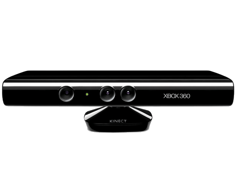 9 9 | 0.8 | 0.7 | 0.8 ± 0.1 | 1.2 | 1.0 | 1.2 | 0.9 ± 0.1 |
| Subj 14 | 1.0 | 1.0 | 0.5 | 0.9 ± 0.3 | 1.0 | 1.1 | 0.7 | 1.0 ± 0.2 |
Morphological characteristics of flatfoot, flattened and valgus foot samples.
With the help of automatic analysis of scanned images of the foot, it is possible to determine the main morphological parameters of 12 feet of 6 subjects (Table 3). The main spatial characteristics of the foot, namely the length and width, correspond to the characteristics obtained using the PodoBox device: the average error was 1.2±1.1% and 0.9±0.7% in length, as well as 9.0±4.1% and 10.2±3.2% in width, respectively, of the left and right foot. The index and width of the arch correspond to the clinical classification; the highest arch index and the lowest arch width score were found in four subjects with flat feet, while the lowest arch index and the highest arch width score were found in 4 subjects with valgus foot.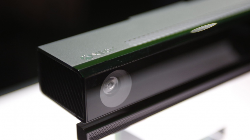
Table 3. Morphological parameters of 12 feet clinically classified as flattened [ 2 ] and valgus [ 2 ] or flat feet [ 2 ]. Arch index, foot length, foot width, arch height and arch length.
| Foot type | Arch Index | Foot length [ mm ] | Foot width [ mm ] | Arch height [ mm ] | Arch height [% foot length] | Arch width [%width] | Arch length [ mm ] | Arch length [% foot length] | |
|---|---|---|---|---|---|---|---|---|---|
| flat #1 | Left | 0.33 | 268.1 | 105.6 | 12.5 | 4.7 | 36.4 | 122.0 | 45.5 |
| Right | 0.31 | 266.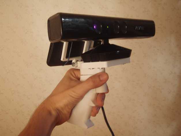 4 4 | 102.5 | 9.8 | 3.7 | 33.3 | 82.0 | 30.8 | |
| flat #2 | Left | 0.30 | 259.4 | 114.3 | 18.8 | 7.2 | 36.4 | 78.0 | 30.1 |
| Right | 0.29 | 258.9 | 117.5 | 18.9 | 7.3 | 31.8 | 82.0 | 31.7 | |
| rectus #1 | Left | 0.27 | 271.9 | 111.0 | 23.6 | 8.7 | 50.0 | 90.0 | 33.1 |
| Right | 0.26 | 268.0 | 113.1 | 20.2 | 7.5 | 46.0 | 76.0 | 28.4 | |
| rectus #2 | Left | 0.26 | 244.9 | 101.4 | 24.5 | 10.0 | 56.8 | 80. 0 0 | 32.7 |
| Right | 0.27 | 239.3 | 103.8 | 17.2 | 7.2 | 52.2 | 82.0 | 34.3 | |
| cavus #1 | Left | 0.10 | 243.0 | 96.7 | 17.9 | 7.4 | 100.0 | 104.0 | 42.8 |
| Right | 0.05 | 243.5 | 101.4 | 17.9 | 7.3 | 100.0 | 88.0 | 36.1 | |
| cavus #2 | Left | 0.07 | 269.5 | 99.2 | 15.6 | 5.8 | 100.0 | 104.0 | 38.6 |
| Right | 0.12 | 268.9 | 102.1 | 19.6 | 7.3 | 100.0 | 86.0 | 32.0 | |
Discussion
In practice, the molded foam method is still preferred. The goal of this method is to develop semi-lightweight insoles. Most of the existing primitive orthopedic scanners, as well as scanners based on laser beam operation, are too expensive for small clinics and non-commercial use. Often, using them, it is impossible to obtain the correct parameters under load. Moreover, there is currently no automatic device that can perform a foot scan other than a 3d scanner. Foot depth sensors, represented by infrared cameras and projectors, are a cost-effective scanning device in relation to laser technology. The purpose of this study was to measure the accuracy and consistency of Microsoft's latest low-cost 3d Kinect foot scanner.
Preliminary tests were carried out to select the optimal parameters for scanning the foot in a standing position on the scanning dish. The 360° rotation of the Kinec sensor is ideal for ensuring the best quality scans of the plantar side of the foot.
Kinect scanner accuracy tested on 14 subjects. A cost-effective, high-quality 3D scanner with laser technology was used for the study. The total mean square error in the construction of a 3d model of the entire plantar surface of the foot turned out to be about 3 mm, which is the same for both the left and right foot. Errors were observed only in the area of the toes and in the lateral aspect of the midfoot region, approximately along with the fifth metatarsal (see Fig. 4). Accordingly, it turns out whether errors are possible when scanning a separate area of the arch of the foot, which is the most revealing morphological feature. The overall standard deviation of the arch shape was found to be 1.5 mm, consistent between the left and right foot. However, the deviation indicator deficiency is rather insignificant, but it is observed during repeated measurements. This fact should be taken into account when developing individual prostheses or when conducting a statistical comparison of morphologically different data.
While the latest scanner shows very good repeatability between scans (from 0.5 ÷ 2.2 mm), the study of the repeatability of the measurement mechanism itself was not carried out in this study.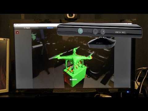 However, since the process of collecting information has become fully automated, the errors in the measurement mechanism have become of the same nature.
Further geometric analysis of the plantar surface of the foot using the Matlab software showed a decent agreement between the obtained 3d scan datasets and clinical observations. In particular, the presumptive arch index with flat feet was higher than with the valgus foot. Although, the width of the arch is the smallest with flat feet and the longest with a valgus foot. The morphological scores obtained by the Kinect scan of the foot seem to correspond to the actual morphological dimensions of the foot, and are also likely to represent objective and relevant measures, in addition to the clinical assessment in the classification of foot types. Although, the average error in measuring the length of the foot was approximately 1%. The same figure in the scanned images was 10% higher than as a result of the measurement using the PodoBox device. It can be explained that this slight increase in foot width results is due to soft tissue compression between the flexible ruler and the surface of the PodoBox (see Fig. 2b).
From an economic point of view, the total cost of an existing 3d foot scanner prototype is around 200-300 euros. Currently, at least a laser foot scanner is presented, the size of which is much larger than the size of a 3d scanner. Using the 3D scanner, resource-limited clinics and research groups will be able to perform 3D scans to accurately diagnose foot pathologies. Moreover, in non-invasive and automated procedures, it is possible to scan the foot under different loading conditions while minimizing assistant involvement. However, the present study and its result should be considered in light of some limitations. Although the accuracy and repeatability results are based, to a large extent, within the extrinsic parameters as well as the intrinsic parameters of the left and right foot, the analyzed foot sample is quite small. In addition, this study analyzed only the foot of an adult. Thus, there is no information available on the use of the pediatric foot device, nor on the repeatability of these results. As a result, all foot data was obtained under ideal conditions without load using a powerful laptop computer; scanned images may be of poor quality and may contain noise.
Conclusions
It was found that the accuracy of the Kinect-sensor without software specially developed for this study can be compared with the accuracy of a laser scanner. Therefore, it is advisable to use the obtained 3d scanned images of the plantar region of the foot for various clinical and biomechanical studies. The latest low cost foot scanner is a worthy alternative to the most expensive laser scanners currently on the market and is suitable for the development of custom insoles as well as orthoses. From a geometric point of view, the scan can be analyzed and measured using special additional software, as shown in this manuscript.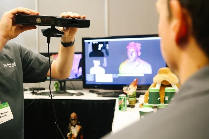 The combination of Kinect scanning with existing analysis software provides a durable automatic foot measurement device, making it easier for podiatrists to obtain foot spatial parameters, species classification, and correct diagnosis.
Availability of data and accessories
Datasets used for analysis during the current study are available from the author upon reasonable request.
Translation notes:
Additive technologies are layer-by-layer building up and synthesis of an object using computer 3d technologies.
Podiatry - treatment of diseases of the feet.
Triangulation method - the acquisition of primary data by various methods from pre-selected sources for the purpose of analysis.
Top Ten 3D Scanners Between $100 and $100,000 There are several ways for you: you can of course create your 3D model from scratch in a 3D modeling program or find a suitable one on the Internet, but you can also scan an existing object! The purpose of this review is to help you understand the variety of 3D scanners available and offer the best in every price segment from a photogrammetric smartphone app to professional 3D scanners.

Scanners are listed in ascending order of price so that you can choose the one that suits your budget and use the resulting 3D models for both 3D printing and animation.
If you are not satisfied with the suggested solutions, there is an extended overview at this link.
3D scanner in hand:
1. Best smartphone app: Autodesk 123D Catch (free)
Autodesk 123D Catch is a free photogrammetric application. It allows you to create a 3D model from photographs of an object taken from different angles. You can use it to scan objects, people, and even the landscape. For some applications, if you don't need perfect accuracy, you don't need special equipment. This application actually provides quite good detail and is easy to use. However, it will take you at least 30 minutes for the app to process your photos as the processing takes place on the server and it takes time to send them.
2. Best DIY 3D Scanner: Kinect ($99.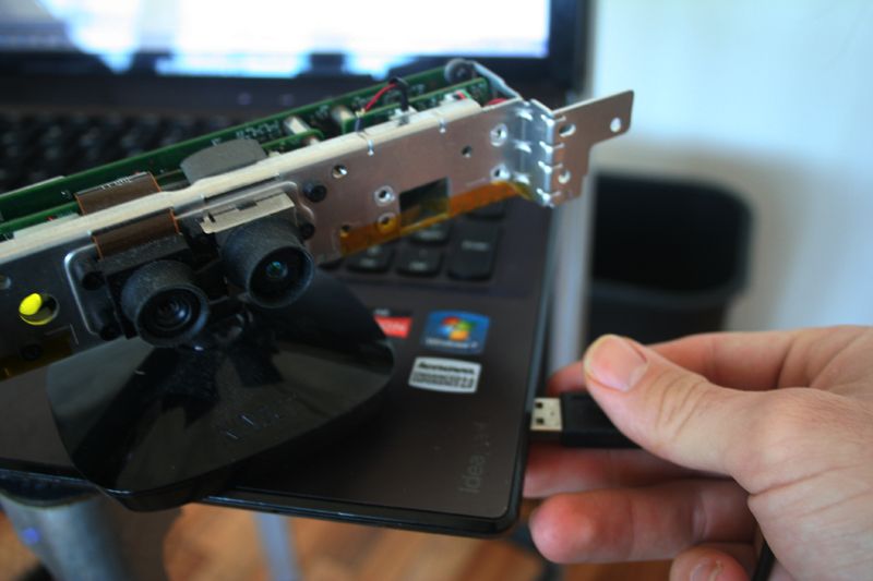 99)
99)
The Xbox Kinect is designed to expand your gaming experience. It is not designed for 3D scanning, but you can easily find manuals and third party software (like ReconstructMe) to turn it into a 3D scanner. If your arms are growing out of your shoulders, this is an interesting and inexpensive solution for 3D scanning.
Price: $99.99
Resolution: 0.051 mm
)
This scanner can be attached to your tablet or phone (generally designed for iPad, but can be adapted to other devices). Lightweight and easy to use, with a very good resolution. Suitable for large items (can scan a full-length person) and outdoor scanning. You will be able to use it with software running on Occipital's SDK. This will increase the resolution and give you access to special features like room scanning. It probably won't be something you'll use for 3D printing, but it's interesting for game development, for example.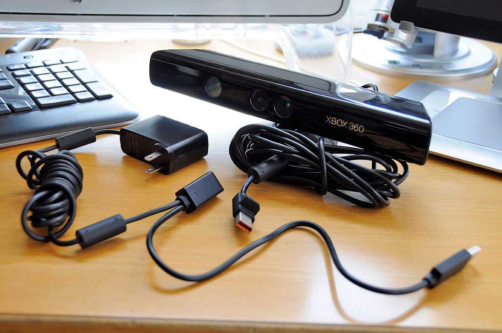
Price: $ 379
Resolution up to: 0.5 mm
accuracy to: 4 mm
4. The best of cheap manual 3D scanners: Cubife ($ 399)
3D scanners can be quite affordable and easy to use if you choose from inexpensive portable models. Cubify fits these criteria very well and has a relatively good resolution. But still, its capabilities are not enough for texture scanning and it is better to use it for subsequent 3D printing of one-color models.
Price: $ 399
Resolution: 0.9 mm
Resolution at a distance of 0.5 m: 1 mm
3D scanner on the table:
5. The best and cheapest table 3D 3D 3D 3D- Scanner: Matter and Form ($519)
If you're looking to take your quality to the next level, you can purchase a desktop 3D scanner. This model is compact, easy to use, and delivers good resolution, especially considering the price (not your go-to option if you're looking for perfection, but great for educational and demo purposes).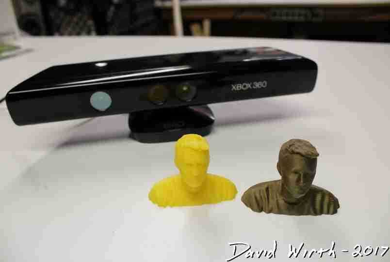 The scanning process takes place with the help of a laser and a rotating platform. The scan takes about five minutes and simultaneously reads the texture of the object.
Price: $ 519
Resolution: 0.43 mm
accuracy: ± 0.25 mm
6. The best device "two in one": XYZPRINTING DA VINCI 1.0 ($ 600)
is an inexpensive device combines a 3D scanner and a 3D printer. The quality of the models is not too high, but the price is very low for such a combined device. This makes the XYZprinting Da Vinci the easiest solution for beginners who want to get into the world of 3D scanning-printing.
Professional 3D scanners:
7. Best value for money portable 3D scanner: Fuel3D Scanify ($1490)
Very easy to use, intuitive, and feels good in the hand, this scanner delivers good accuracy and texture quality. The only limitation is that the size of the scanned area is limited, which is great for small objects, but for scanning a full-length person, for example, it will not work.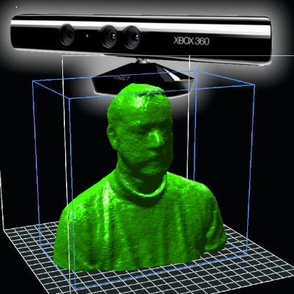
Price: $ 1490
Resolution: 0.35 mm
accuracy: to 0.3 mm
8. The best price for desktop 3D scanner: David Laserscanner-SLS3 ($ 3995) 9000 9000 9000 9000 9000 9000 9000 9000 9000 9000 9000 9000 9000 9000 9000 9000 9000 9000 9000 9000 9000 9000 9000 9000 9000 9000 9000 9000 9000 9000 9000 9000 9000 9000 9000 The scanner uses a different scanning technology than others. Instead of a dual laser scanning system, it uses a structured light source and cameras for fast scanning with very fine detail down to 0.06mm! The scanner comes with DAVID Pro Edition 3 software that works with OBJ, STL and PLY 3D file formats that can be exported to other programs for further editing.
Price: $ 3995
Resolution: 0.06 mm
accuracy: 0.5% of the size of the object
9. The best desktop professional 3D scanner: Solutionix Rexcan 4 ($ 79 900)
This is a professional The 3D scanner and its price provides much better scanning quality.