3D printer ring
3d Printed Ring - Etsy.de
Etsy is no longer supporting older versions of your web browser in order to ensure that user data remains secure. Please update to the latest version.
Take full advantage of our site features by enabling JavaScript.
Find something memorable, join a community doing good.
(1,000+ relevant results)
11+ Stunning 3D Printed Rings - From Casual To Question Popping
Making your own jewelry is a hobby many of us claim to have at least dabbled in, and now that 3D printing lets us be a lot more precise with our measurements, 3D printed rings are a new way for us to continue this craft.
It’s easy to see why every time a new art form is brought to the common household, people tend to gravitate towards making things that they can wear.
3D printed jewelry has been at the top of many a 3D printing enthusiast’s to-do list for a long time, from necklaces and earrings to bracelets and brooches. 3D printed rings, however, are a little trickier.
Rings are always on display, as we use our hands so often. Because of this, they can be significant features of our wardrobe. Whether it’s the insignia of our alma mater, a family crest, or any other symbol that’s dear to us, 3D printed rings let us find new ways to always keep something close to us in our thoughts.
Unlike things like necklaces and bracelet, rings need to be an exact size to be worn comfortably. Too loose and they’ll fall right off, too tight and they’ll not go on or – even worse – not come off at all. So always make sure to know your ring size before settling on your design.
This gets a little more complicated if you’re making a 3D printed ring as a gift, doubly so if you’re looking to craft a 3D printed engagement ring, but knowing the correct size is important to be immediately worn.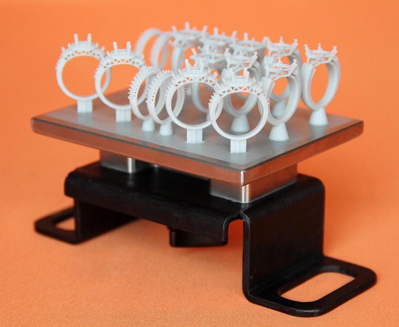 But don’t worry, you can always surprise them with a prototype and then tweak the measurements for the next print if needs be.
Here we’re going to look at some of the best 3D printed rings, from gimmicky to meaningful, gift to personal, and how to make sure they come out just right.
Fun 3D Printed RingsIf you’re unable to print with metal, then you may not be able to 3D print a ring that matches what you’d find in a good store, but that doesn’t mean there isn’t some fun to be had. Here are some of our picks for the best 3D printed rings to wear for the heck of it.
Gothic Punk Skull 3D Printed Ring
Elegance and darkness often go hand in hand. The allure of night hiding our sins, knowing the workday is over and we can be our true selves. If your true self has even a hint of goth, then this 3D printed ring is not to be overlooked.
The immaculate detailing and spine-tingling expression are a great combination. This ring is an excellent addition to any black ensemble, and shouldn’t be confused for a simple Halloween decoration.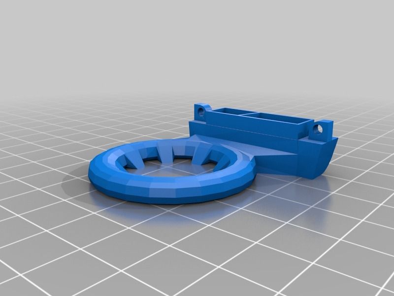
Lucky Elephant 3D Printed Ring
Sometimes simplicity is key, but there are times when a balance is needed to make something truly special. This 3D printed signet ring has just enough detail to be an impressive piece, but not so much that it distracts from the overall quality.
The lighter the color of filament you use, the better the elephant’s features will stand out, but it can be silhouetted if printed in a darker shade. If you’re a fan of the design, then we recommend printing multiple versions to match any outfit or style you’re going for.
The elephant is seen to bring luck and wealth (provided they aren’t white, of course) and this makes a great gift as a good luck charm or as a simple present for any elephant fans in your life.
Green Lantern’s Ring
If you’re a comic book fan, chances are you thought of this the moment you thought about making a 3D printed ring. Naturally, the internet does not disappoint, providing this excellent recreation of the ring worn by The Green Lantern of DC fame.
While we could have selected any number of the Green Lantern rings available for 3D printing, this one caught our eye because the files allow for multiples to be made at once.
This is perfect for printing and sharing with friend groups as a symbol of your friendship bound in a love of comics, or as a forget-me-not for those moving away.
Whatever your reasons, this easily recognizable and truly iconic 3D printed ring is a great way to show off your fandom.
Lord of the Rings 3D Printed RingPerhaps the only fictional ring better known than that of The Green Lantern is the Ring of Omnipotence from the legendary series, The Lord of the Rings.
The Black Speech language of the inscription is perfect to the last detail, and this design is suitable to be printed in just about any material, so you can get as fancy as you like with this piece of memorabilia.
Perfect as a personal item, gift, or even decorative material for your bookcase; the one ring to rule them all has never been easier to own for yourself.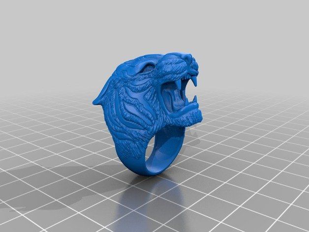 Invisibility not included.
3D Printed Bird Rings
The grace of a bird in flight is an undeniable wonder of the world, and the innovation of turning that wing flap into a wearable piece of 3D printed jewelry is why I’ve included these rings on this list as my personal favorites.
The files found here come as a bundle of four, featuring an eagle, an owl, a raven, and a swallow. Each bird’s wings form the circumference of the ring, and the detailing in their feathers and faces are impressively detailed.
Because these come in a file pack of all four, they are also perfect for gifts amongst close friends as well as additions to a personal jewelry collection. If printed in plastics, smoothening the surfaces with acetone will give them a polish and sheen just like the example photos.
Two of the rings even have particular inspirations from franchises I personally love. The owl was inspired by the famous mind-bending TV show Twin Peaks, while the Raven was inspired by The Longest Journey, better known now as Dreamfall. Yes, the bird in those games was a crow, but who’s keeping track?
3D Printed Engagement Rings
With wedding ceremonies leaning more towards do-it-yourself and destination celebrations, more and more people are paying less attention to old traditions in favor of modern and personal experiences for their special ones and special days.
Because of this, 3D printed wedding rings are a very popular choice for those who want to commemorate a once-in-a-lifetime love with a homemade 3D printed engagement ring.
If you have a metal 3D printer, or a 3D printer that can print metal filaments, then you can design anything yourself from scratch. Though metal doesn’t have to be the material of choice if you can’t.
Though don’t be disheartened if you can’t print in metal, as any one of the designs we’ve talked about here would work as a 3D printed engagement ring depending on your wants and interests.
Designing an engagement ring from scratch is as simple as knowing the measurements and including an inlet for any gemstone you want to use.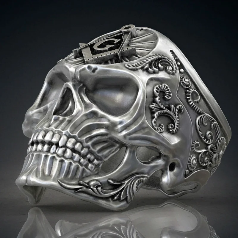
3D Printed Ring Holders
Now that you’ve decided on what 3D printed rings you want to make, you’re going to need somewhere to keep them. Rings are smaller than a lot of other pieces of jewelry and are quite easily lost.
Because of this, here are a few 3D printed ring holders to keep your creations safe and on display.
6 Post Ring Stand
If you’ve gone for multiple rings, then this 3D printed ring stand is the perfect addition to your bedside or vanity table.
Its design is simple and should fit rings of any size. If you have specific uses in mind, you can alter the files to include the names or types of each ring so they have a dedicated post of their own.
Wall Mounted Ring Stand
Coat hooks hold our jackets, hat stands our hats, in that vein, there’s this 3D printed ring holder that can be mounted to your wall via hook or screw so you’ll always know where your favorite rings are.
The files here come in sets of two, and you can print as many as you need to hold all the rings you own or have made along the walls of your home. The hangers come in three different types to suit any size of ring, ensuring they won’t fall off easily. The general size of each mount is also small enough to be achievable for any 3D printer.
Double Use Watch and Ring Stand
Rings aren’t the only things we need to keep safe, and many of us have watches that are dear to us for one reason or another. For those cases, this 3D printed ring holder doubles as a watch stand to keep our things secure.
The small inlet allows for rings to be kept safe next to the watch, and the design itself is quite attractive and shouldn’t look out of place on a vanity table.
Other articles you may be interested in:
- 3D printed jewelry: best brands and most stunning pieces
- How 3D printing entered fashion
- 3D printed clothes: feature story
- Best jewelry design software
- Best 3D printers for jewelry
- 3D printed items you can print and sell
3D printed jewelry - ideas
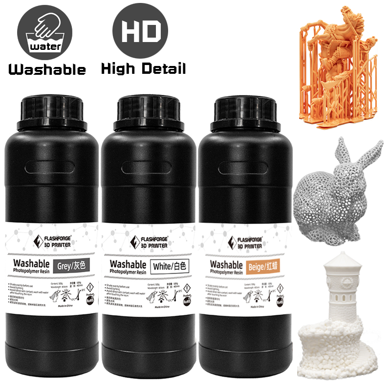
The technology of photopolymer 3D printing is rapidly improving and is increasingly being used in the jewelry industry.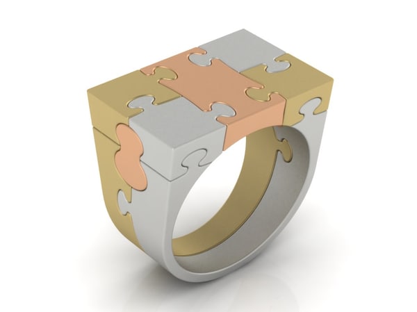 3D printing in jewelry is no longer a rumor, but an established reality. Rings, bracelets, brooches, earrings of the most unusual shapes can be printed on a “magic” 3D printer and then cast from metal.
All you have to do is choose a 3D printable file online or create your own 3D model using a 3D jewelry design software like 3Design, MatrixGold, etc. The file is then “cut” into layers in a special slicer program, appropriate settings are selected on the 3D printer and printing is started.
You can read more about the technology, comparing it with traditional manufacturing methods, and application examples on our blog in the Jewelry Making section.
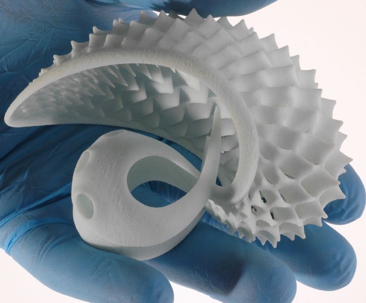
Examples of unique jewelry that can be created with resin 3D printing:
3D printed skull ring
Skull rings are a common fashion accessory. They are worn by both men and women, regardless of style and occupation. The symbol of the skull, as the infinity of life and wisdom of the ancestors, is one of the most common and ancient in the history of mankind.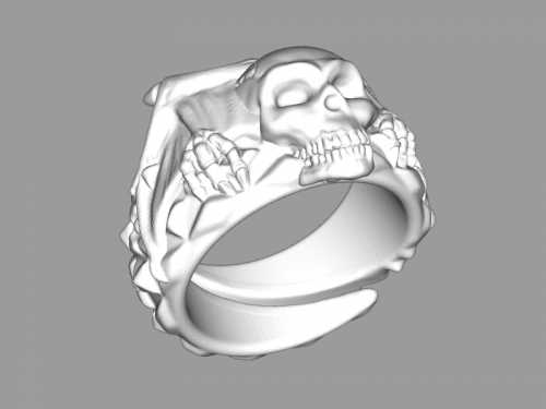 Traditional jewelry making methods require long and painstaking processing of small and intricate details of the ring. A 3D printer will print it out for you, like Phrozen Sonic Mini 4K or Phrozen Sonic Mini 8K.
3D printed flower ring
A flower ring is something that almost every girl wants to have in her collection. For many of them, this is a must-have accessory. Flowers come in different sizes and styles, small and large, thin and graceful, or, conversely, massive.
For 3D printing, you can use model or burnout resin. According to the burnt-out model, in the future, you can cast a metal decoration. The range of resins is very large, there are high resolution 4K and 8K resins for creating highly detailed models. Models shown are in Phrozen Wax-like Castable Violet.
3D printed anchor
Anchor pendant is an incredible piece of jewelry inspired by the sea. It has a special meaning for people close to the sea. The anchor is a symbol of hope, stability and confidence in the future.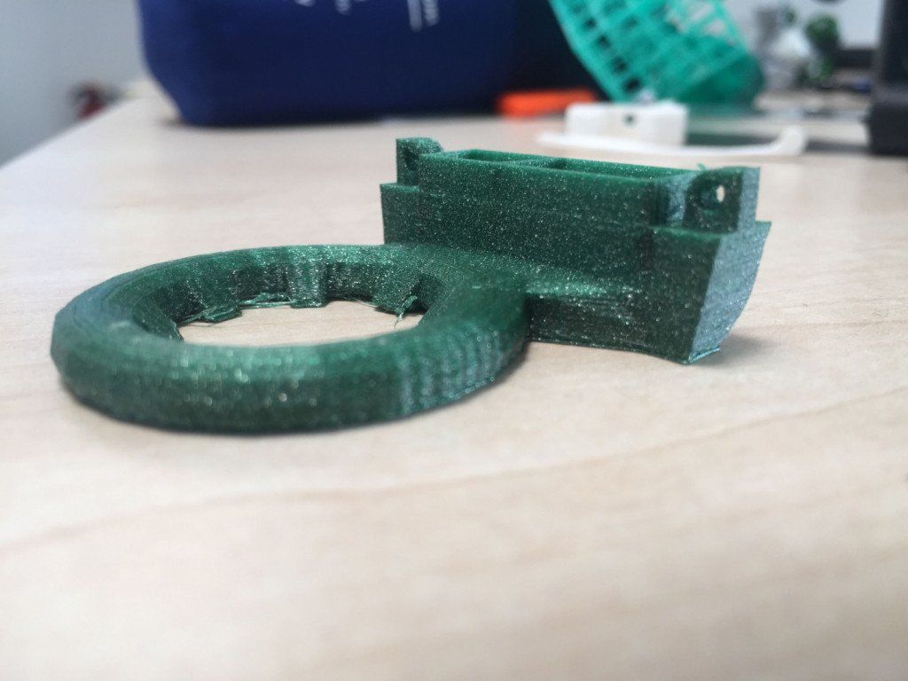 It is associated with a ship that has landed on its native shore.
3D printed tiger pendant
According to Chinese astrology, this year is the Year of the Tiger! This means that people all over the world will wear tiger-themed jewelry.
3D printed bouquet brooch
A brooch-bouquet is another fashionable decoration. Just look how delicate this brooch is. 3D printing did an excellent job with her intricate details.
Conclusion
With 3D printing, you can create an unlimited number of designer jewelry. You can create a one-of-a-kind unique decoration. The detail is amazing. At the same time, jewelry 3D printing definitely increases the production capacity of the enterprise. Many modern manufacturers are using resin 3D printing technology as a way to save time and money in the long run.
3D Printing and Jewelry: Basic Design Parameters, Supports and Orientation
Introduction
To better understand the methods and parameters for developing digital design for 3D printing, it is important to understand how the Form 2 stereolithography 3D printer works. In addition to the process of hardening and creating very thin layers of polymer with a laser, the layers are subjected to shear forces during printing as the printer sheds and prepares each successive layer. Understanding the forces involved during printing helps in understanding the parameters for both design and printing.
This article assumes the use of knowledge of the CAD program in the modeling process with files that can be converted to STL or OBJ format. We used Rhino5, but the same principles apply to any CAD software you are comfortable with. The models shown as examples do not claim to be of aesthetic value, but were created to demonstrate the principles described.
Another technical process, casting, also affects how the model is developed. Just because you can print a model on your Form 2 doesn't mean it will run successfully.
Download detailed manual
3D Printing Mechanics
OVERVIEW
Printed parts are created on the Form 2 build platform in very thin layers, one per pass. After each layer is printed, the platform resets to allow the next layer to be printed. PreForm is free print preparation software from Formlabs. PreForm allows you to load multiple 3D files and then orient, position and support your designs before sending them to the printer. It is not a design tool or replacement for CAD software.
PRINTING PROCESS
Form 2 uses a laser to cure a layer of resin between two surfaces dipped in a resin reservoir in a process called curing. The laser traces a path through the resin layer, defined by the cross section of your part at different heights, and starts at the "bottom" as shown in the PreForm software. PreForm assists in this process by cutting the slices to a thickness determined by the layer height you choose. For jewelry models with fine details, a layer height of 25 microns is recommended. The thinner the layer height, the more layers PreForm will form, resulting in finer details but longer build times.
The layout displayed in the PreForm (Fig.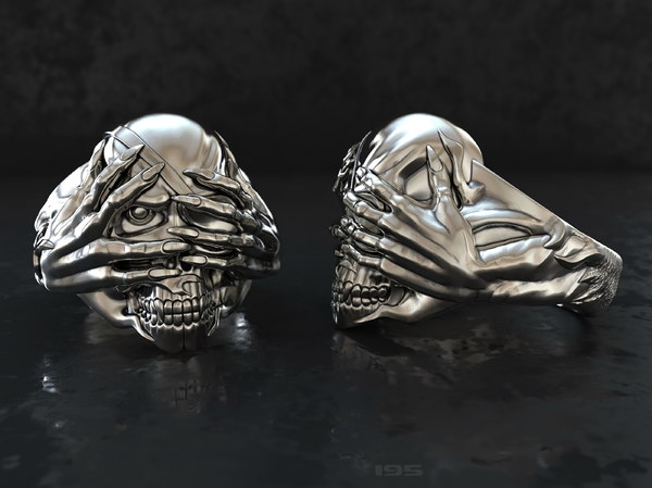 1) shows how the print will be built, where it is on the "floor" plane, from the "bottom" part to the top of the part. The view in PreForm is reversed in relation to how the part will be printed in the printer (Fig. 2). PreForm renders the bottom of the platform on top. In the printer, this surface sinks down into the resin bath, essentially building your part upside down.
Figure 1: View in PreForm.
Figure 2: Printer Orientation
During the laser curing process, the resin adheres to the build platform and subsequent resin layers and adheres weakly to the optically clear silicone surface of the resin reservoir. The thickness of each layer is determined by the distance between the two surfaces. For example, when you set a layer thickness of 50 microns in PreForm, the machine will use this thickness to set the surface spacing for each successive layer (fig. 31).
After each layer has cured, the platform and attached layers must be peeled off the silicone surface of the resin reservoir.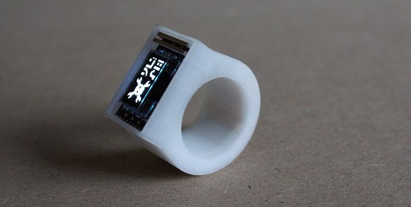 The reservoir moves sideways with respect to the platform to achieve this and must overcome the adhesive and suction forces holding the polymer layer to the silicone surface. Although they are significantly weaker than the forces holding the part to the platform, these lateral forces can cause distortion or distortion in the printed part if they are not compensated for.
Resin flow in the tank, created by the lateral peel movement, is another force acting on the part. The platform rises above the surface of the resin tank to allow the cleaner to remove any particles or debris from the build area that might interfere with the hardening of the next layer, and the resin circulates in the tank (Figure 3.2)
Various resins used for printing are first cured in a specified shape after exposure to a laser beam. This initial molding process does not fully cure the polymer. 3D parts right after the printer are often referred to as being in the "raw state".
After printing is complete, the part must be fully cured with a combination of heat and light.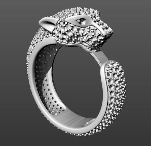 Standard materials such as grey, white and black resins can be used for presentation models in the "wet state" without further curing. Functional polymers, in particular Castable Resin, require additional curing as they are quite soft when wet. A fully cured part will result in a better casting result. Thin parts cure more easily than thick parts and the advantage of thin and light parts is that they have less mass to control during the peeling process.
For more information about the curing process, see the booklet: How the mechanical properties of 3D stereolithography change during UV curing.
Fig. 3.1: Not actual size, layer height increased for details.
Fig. 3.2: Tank moves horizontally, platform is raised, cleaner moves horizontally. Not actual size, layer height increased for parts .
Digital Design Fundamentals for Printing and Casting
OVERVIEW
In addition to creating beautiful designs, jewelry designers must work within cost and process parameters, paying close attention to wall thickness and weight.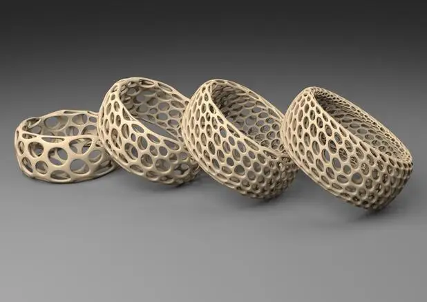 Jewelry is generally designed to reduce weight due to material costs (precious metals) and wear resistance, while still giving the illusion of reassuring volume. Maintaining a low weight and low wall thickness helps achieve successful prints in a shorter time and requires less resin to build. A useful general resource on guidelines for technical details can be found in the Formlabs design specifications.
The casting process has its own success parameters, which will be discussed in this section.
Just because you can print your design doesn't mean you can successfully apply it!
This document provides a broad overview of some of the fundamental principles of digital design for jewelry printing and casting, and therefore will only cover some of the basic principles and explanations. Please note that the following information is provided as one of many approaches to the technical aspects of digital modeling and we welcome feedback if you agree, disagree or use a different way to model your jewelry.
WEIGHT AND MINIMUM WALL THICKNESS
As described above, significant forces are applied to the print as it is built in layers.
If a part is designed to be very heavy, it will require more support during the printing process than a lighter part. If the part is designed to be very light, other measures must be taken to ensure successful printing and casting.
When designing small, lightweight parts, observe the minimum recommended wall thicknesses for best results. The annular specimen shown below (Figures 4.1 - 4.3) is modeled to demonstrate the results of the same model with three wall thicknesses: 0.3 mm, 0.5 mm and 0.75 mm
The wall thickness of 0.3 mm (fig. 4.1) entails two main problems: the printable walls are not straight, but significantly concave. This is a result of these very thin walls being subjected not only to peel and flow forces during the printing process, but also to any slight shrinkage of the polymer during the print curing process and subsequent post-curing.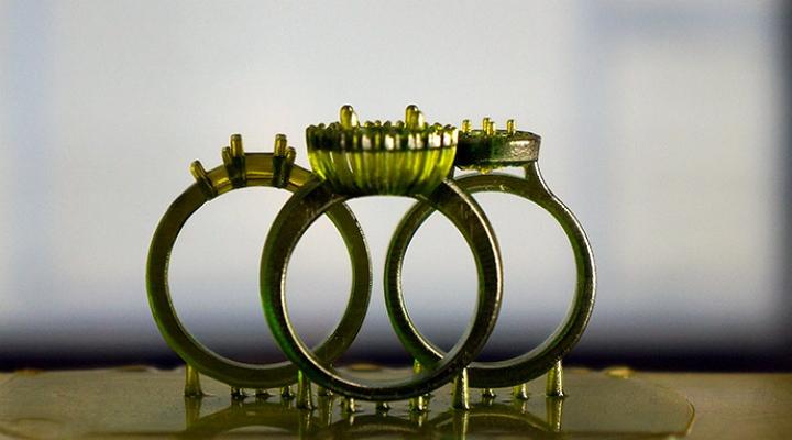
The casting is not completely filled on one side due to thin walls. If multiple casting attempts are made, the part may or may not fill completely, but there is no way to overcome the warping of the printed part.
With a wall thickness of 0.5 mm (Fig. 4.2), we see a reliably filled filling, but there are some distortions and concavity in the side walls. We used the file to make some photographic cuts along the surface to show that the surface is indeed concave. It would be possible to continue filling to make this surface perfectly flat, but this would result in dangerously thin walls that would not support the load of a customer wearing the ring.
A wall thickness of 0.75 mm (Figure 4.3) works well at this scale with reduced distortion. The same few surface cuts produce very slight surface depressions that can be easily filled flat without significant loss of wall thickness. The result is a structurally strong ring that will withstand everyday wear.
Fig.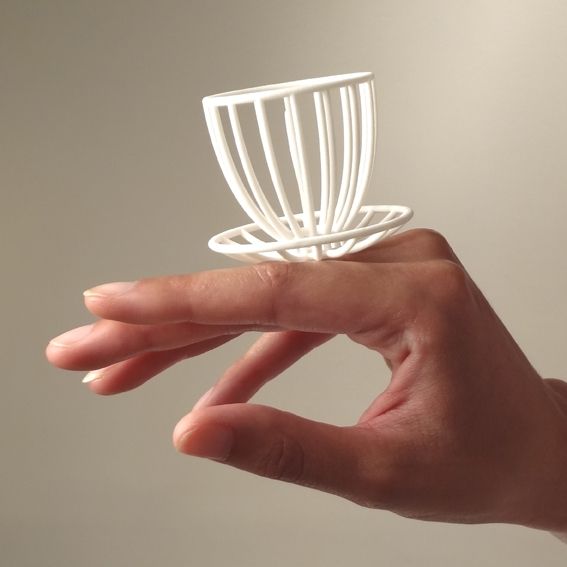 4.1: Hollow center section with a wall thickness of 0.3 mm Pay attention to deformation of the surfaces and incomplete filling.
Fig. 4.2: Hollow center section with 0.5 mm wall thickness Filling the entire flat surface shows contrast with the concave center wall.
Fig. 4.3: Hollow center section with a wall thickness of 0.75 mm Filling the entire flat surface demonstrates the integrity of the flat surfaces.
Large parts must be designed with practical weight for printing and fabrication. If the part is too heavy, the print will need a stronger network of supports so that it doesn't come loose from the assembly supports during the peeling process.
From a practical point of view, heavy parts increase the material costs of both the final cast metal and the resin used for printing, and possibly cause customer dissatisfaction due to uncomfortable wearing. If a part is designed too light, it faces potential distortion caused by peel and cure forces.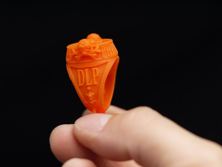 Parts that are too light cannot be cast due to walls or components that are too thin to properly fill during the casting process, as noted above for small parts.
In general, in handcrafted jewelry, large pieces should be designed in hollow shapes with a minimum wall thickness that will maintain structural integrity and allow for everyday wear. The figure shows a 18mm wide hard bracelet that has a wall thickness of 0.9mm.
The three options are shown on the next two pages (Fig. 5.1 - 5.3) The first option (Fig. 5.1) is printed with a solid surface, except for a small hole with a diameter of 3.5 mm, which allows internal cleaning with isopropyl alcohol (IPA) and filling the hollow bracelet with molding sand for casting.
Figure 5.1: Digital and printed model of a hollow bracelet with one small sand hole. Note the support structure needed to assemble this part (see Orientation and Supports section).
The surface produced on the Form 2 is smooth and consistent, creating a shape and surface ready for small hole plate welding and finishing.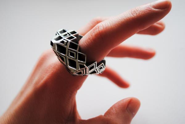 Unfortunately, this part cannot be cast.
The main reasons why any attempt to cast this part will fail are:
Flushing and Curing: It is very difficult to flush and cure the inside surfaces of this hollow mold, and the uncured resin can react with the sand, causing a casting error.
Molding Sand 1 : it would be very difficult to completely fill the inside of the bracelet with sand, and even if it were completely filled, it would also be difficult to remove the sand after casting.
Sand 2 : When the polymer burns out, a large volume of sand is left in the shape of the inside of the bracelet, floating in a space known as the core, supported only by a 3.5 mm mixture cylinder, which was the hole. This small cylinder of sand cannot support this core, especially when the molten metal is poured at high speed into the flask.
The second option (fig. 5.2) simply adds more and more access holes to the hollow inner bracelet.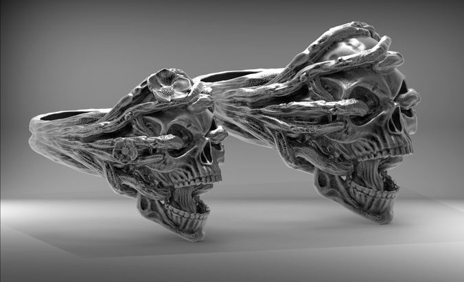 These holes can be decorative and serve as an integral part of the design.
Fig. Figure 5.2: Digital model of a hollow bangle with several large holes on the inside to allow for successful addition of sand and casting.
The third option (fig. 5.3) creates a bracelet from several parts. Use this approach if you want to cover all surfaces, or if you want to create a decorative pattern through the inside of a bracelet that has perforations too thin to successfully add molding sand and cast the bracelet as one piece. Building supports and keys in the model greatly simplifies assembly.
5.3: Digital and printed model of a hollow bangle with a decorative inner surface. This example shows a perforated filigree surface type split into multiple pieces (one of the six interior surfaces shown) that would prevent full and successful sand fillings when printed as a one-piece bracelet.
PROCLE SETTINGS FOR SMALL STONES
Most jewelry can be broken down into its individual components. All of these components must not only be printable, but also usable. If we look at traditional gemstone jewelry, we see separate stone settings (“settings”) and the structure to hold these settings together. Considering the example of a ring consisting of several bartacks, we can break these bartacks into prongs and frames. The ring shown below (Fig. 6) has an 8mm center stone and 2.5mm side stones.
For these 2.5 mm side stones, the rim thickness was 0.4 mm and the prong diameter was 0.7 mm. Although for such small parts the thickness of the rim can be successfully printed at 0.3 mm, such a thin wall can be problematic for casting.
If the casting is successful, finishing this casting can reduce this thickness to a dangerously thin wall. The 8mm center stone has proportionately larger bezel and prong dimensions of 1mm and this poses no problem for both printing and casting.
6: Digital, printed and cast model ring for 8mm center stone with 2.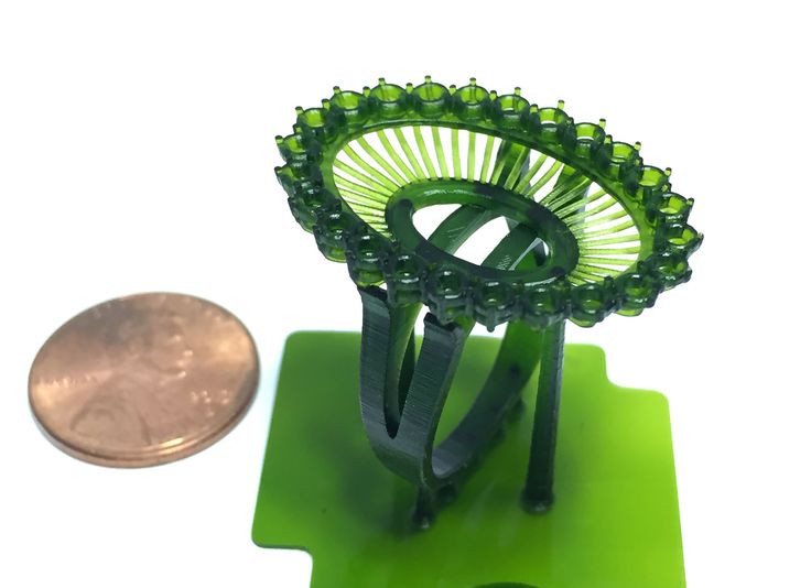 5mm side stones.
When smaller stones are installed inside the walls, similar considerations must be taken regarding the thickness of the walls on either side of the stones and the diameter of the claw. For this type of structural and visual application, the wall thickness should be at least 0.5 mm and the prongs should be at least 0.5 mm.
If you create your model with vertical walls and prongs close together to fill the space with rocks, the prong may merge with the side wall during the printing process (fig. 7.1). Even if it maintains its position, then the sand will almost certainly break at this point, and the prongs will merge with the wall (fig. 7.2 - 7.3)
CASTING AND GROUND NOTES:
Wax casting (or, in our case, resin casting) technique is based on sealing the part with a refractory material, a sand, which forms the shape of the part and allows molten metal to fill the exact the area of the part, after which this part is completely removed when burning at high temperature.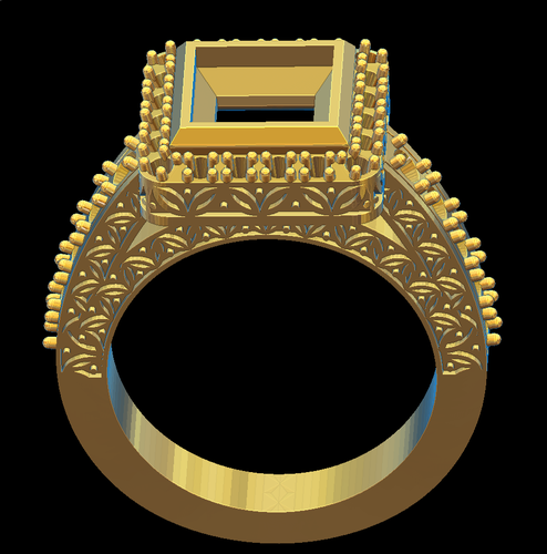 Molding sand is very heavy, but as with very hard materials, it is also very brittle.
Digital design for metal casting requires an understanding and planning of negative (molding) as well as positive (polymer or metal after casting) spaces.
In the example above, consider how little space is left between the prongs and the walls for sand. After some of the polymer has burned off, this very small piece of the mixture must withstand the force of the molten metal rushing into the mold at high speed. In this case it won't happen.
This gives two extremely important results:
- The sand breaks and the metal just runs freely between the prongs and the wall
- Tiny mixture particles are present in the molten metal mixture. These particles cause voids, and they can also appear in the metal near the surface. There are few things worse than a final polish showing pieces of the mixture.
These images illustrate vertical walls and prongs, and a very thin sand line between prongs and wall.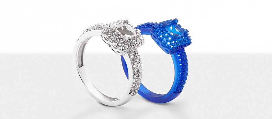
Figure 7.1: Digital ring model with 0.5 mm straight walls and 0.5 mm straight prongs.
Fig. 7.2: Injection printed ring, molded to burnout and cast, showing distance between walls and prongs.
Fig. 7.3: Mold sand after burnout of the molded part, before casting, showing negative spaces in the sand between the wall and the prongs.
One way to solve this problem is to add slope to the side walls and prongs (fig. 7.4 - 7.6). The "tilt" turns these walls and prongs so that they form a cone from the thicker base to the thinner top, and usually a 5 degree angle is sufficient to improve castability without being in the way. If the design allows it, then a large angle of inclination will always help better.
This creates a stronger piece with visually thinner edges and more space between the top of the wall and the prong so that the mix is stronger to withstand casting forces. There may be some space closure where the prong meets the wall at its base due to printed and cast artifacts, but the top of the space will be defined and more easily molded.
This space, which previously only existed in the digital file because it was too small to be cast before the slope was added, allows for safer casting and provides a guide for setting stones.
Although skew is outside the scope of this article, skew in such details in the model also improves results in the molding process and subsequent wax injection processes. See our document Vulcanized Rubber Injection Molding with 3D Printed Master Molds for more information on the process.
By applying the angle to our prongs, we increase the sand line between the teeth and walls to improve casting success.
Figure 7.4: Digital model of the previous ring (Figure 7.1) with a 5 degree slope in the side walls and prongs.
Fig. Figure 7.5: As before (Figure 7.2), the revised sand piece shows the increased space between the wall and the prong.
Fig. Figure 7.6: As before (Figure 7.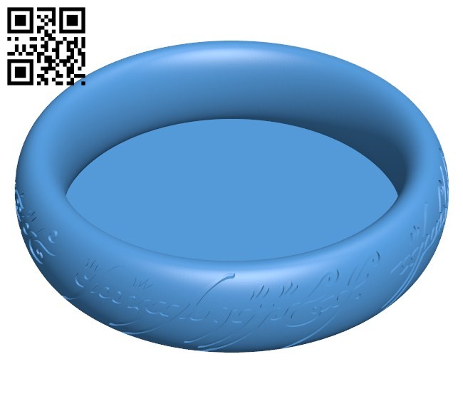 3), the sand after burnout of the revised part, showing the increase in the thickness of the sand between the wall and the prong
HOLES
For all practical purposes, holes should have a minimum diameter of 0.5 mm, and this diameter should only be used for holes in very thin material. You can use smaller holes, but the results may be inconsistent with both printing and casting. In the ring below (Figure 8.1), a 0.5mm hole has been modeled in the center of the bottom bartack bar (most likely this hole is not needed, but it's a good example!). Such a small hole in a relatively thick piece of metal runs the risk of sand breaking during casting and hole filling.
A filled hole can always be drilled, but as mentioned above, having a filled hole means there are broken sand particles in the casting that can cause a defect. One solution is to simply indicate the ends of the through hole by dividing the sphere at both ends of the hole, providing a guide for the drill (Figure 8.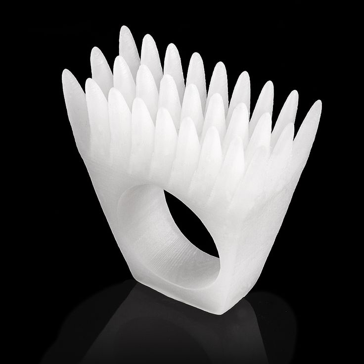 2).
2).
Fig. 8.1: Digital model of a ring with a 0.5 mm hole that can be filled during casting. Please note that this hole size is for illustration purposes only. If it was a "real" model, the hole would be closer to 1.5mm and would be cast successfully.
Fig. 8.2: If small holes are needed, drill them after the part is cast. Create a shallow recess for which there will be no problems with casting. This will give an accurate drilling template.
Another solution for printing and casting small through holes (fig. 9.1) is to add an openwork decoration to the back of the hole (fig. 9.2). Not only does this help with printing and molding, but it saves weight and adds a decorative element.
Fig. 9.1: Casting the ring leaving small round through holes behind the stones. Fig. Figure 9.2: Ring casting modeled with rectangular openwork holes around round stones to add visual interest and improve castability.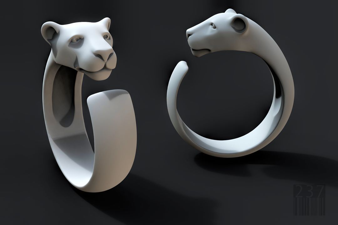
INTERNAL CORNERS
As we saw earlier, it is important to consider negative spaces in your design, especially internal corners, which can cause the problem of sharp sand edges breaking into parts during casting. Consider the flow of metal into the mold and how to make this flow as smooth as possible. Sharp edges, rough finishes, and even sharp or compressed edges from supports that have not been completely removed can cause turbulence in the liquid metal. At best, the casting will be fine. In the worst case, this turbulence can cause porosity (imagine an oncoming wave). If possible, round the inner edges (fig. 10.1 - 10.2), and if the design allows, also the outer edges (fig. 10.3 - 10.4). Spend time finishing your print, smoothing surfaces and removing any artifacts
Fig. 10.1: Sharp corner (negative space) in the shoulder of the shank, positive sand space may break during casting.
Fig. 10.2: By rounding a sharp inside corner, positive sands become much stronger.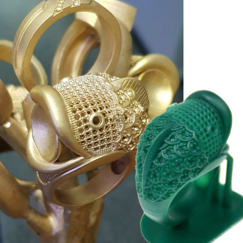 Overriding this angle by engraving when finishing is a simple solution.
Fig. Figure 10.3: Sharp internal corners in this square hole create turbulence and a potential risk of sand breaking.
Fig. Figure 10.4: Rounding inside corners provides stronger edges and smoother metal flow during casting.
ENGRAVED DETAILS
Everyone wants an engraving inside the ring! If the images and text are large enough, engraving shouldn't be a problem. If very fine engraving is required, the best solution is to find a good laser, machine or hand engraver. In the examples given (Fig. 11.1 - 11.4), the letter E was used in different fonts. One ring has letters engraved to a depth of 0.3 mm (Fig. 11.1), and the other - to a depth of 0.5 mm (Fig. 11.3). As with any features built into a part rather than applied on top of it, these negative spaces must be created with a slope. The height of the smallest letters is 1.5 mm, and the smallest letters of decorative type tend to fail at both depths.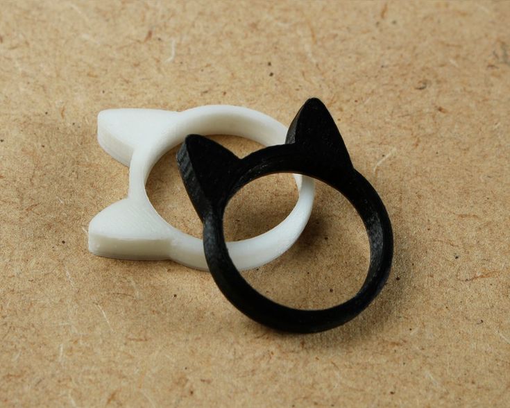 This is mainly due to the sand not being able to handle these thin and intricate details, and also because your printer is approaching the limit of printing very small negative objects.
These small letters seem to improve a little at the shallower depth of 0.3 mm, due to the fact that the mixture that fills these spaces becomes shorter and therefore stronger. When the mixture does not withstand loads, particles of this destruction can cause damage to the casting. For very small engravings, these should be outsourced; for large letters or images, find out how these objects can be printed
11.1: Printing a ring with an engraving depth of 0.3 mm.
Fig. 11.2: Casting of a ring with an engraving depth of 0.3 mm. Note that although the smallest font E is displayed, by the time the ring is completed and polished, the engraving may have lost all outline. 11.3: Printing a ring with an engraving depth of 0.5 mm.
Fig. 11.4: Casting of a ring with an engraving depth of 0.5 mm. Note that the smallest letter is better defined and may survive to the end, but not guaranteed
SURFACE RELIEF
When adding small details raised above the surface, consider the finishing process. Even the most perfect casting comes out with a matte surface, and in the case of resin prints, some artifacts appear due to the creation of layers during the printing process.
Although Form 2 produces an exceptionally smooth surface, these microscopic layers may remain visible in the casting. The surface of the casting is usually cleaned (polishing process), then polished (subtractive process) to obtain the final finish. The polishing process removes material and if the surface detail is too thin, that detail will be reduced and lose visual effect during the polishing process.
A simple and effective solution is to highlight the relief. The image below (Fig. 12) shows a 0.3 mm "wire" in a grooved shank.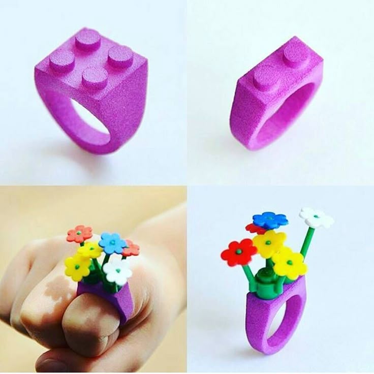 This will be lost or reduced in strength by the time the part is finished. By exaggerating the depth of the groove and the height of the "wire" while maintaining the same width of 0.3mm, the final finished parts achieve the desired effect better.
Figure 12: Digital image of the design relief on the left and exaggerated relief to achieve the designed effect after finishing.
WATERPROOF MODELS
To get the best print possible, it is important to make sure that your digital model is "waterproof", which means that all surfaces of a solid object are joined without any open seams. Check for open seams using analysis commands such as "show edges" in your CAD program. Repairing models is not always an easy task and is beyond the scope of this article.
Another important detail to note is the difference between grouped components and logical components. Grouping collects several separate designs and allows them to be manipulated as a single part, while the logical process creates a single design from several separate designs.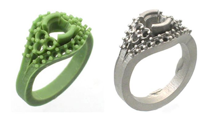 PreForm, whose software prepares models for printing on the Form 2, is able to eliminate many problems, such as open seams and grouped or logical parts.
Grouped and "leaky" (as opposed to waterproof) parts are sometimes printed after repairs in PreForm. However, sometimes PreForm cannot fix all the errors in your file and allows you to print anyway. The image (Figure 13) is the same detail, one from a grouped file with some exposed edges, and the other from a logical and waterproof file.
The most reliable approach is to check and correct your digital models before sending them to the printer
Figure 13: The top print is the result of printing a file using grouped components without proper connection into a "watertight solid". The bottom seal is the result of the same elements, joined together correctly, forming a "watertight solid body".
Orientation and Supports
SUPPORTS
As previously discussed, printed parts are built up by curing successive layers of resin between the build platform and the clear surface of the resin reservoir.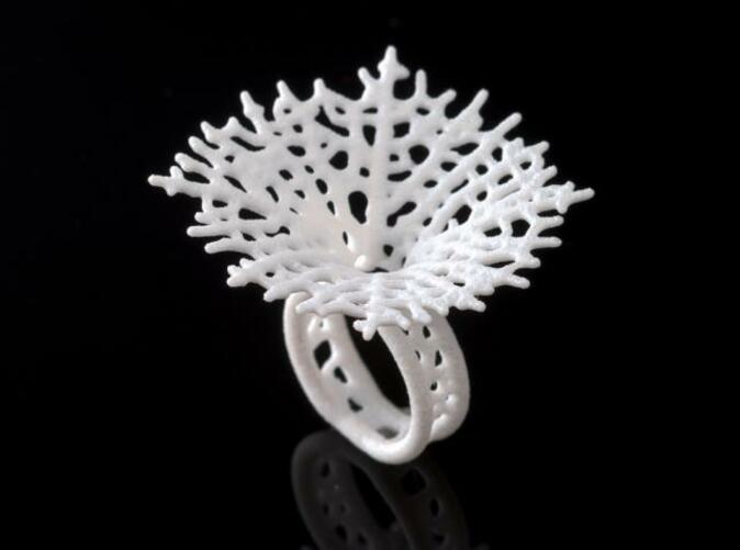 The layers solidify in the space of the assembly area according to the geometry of your model. The layers must be bonded to the build platform or each hardened layer will just float in the tank.
Supports descend from the surface of the build platform to the part and maintain part anchoring so subsequent layers build accurately on top of each other without floating. The PreForm slider tool, located to the right of the screen, lets you drag them up and down to check each layer individually.
Check. that each layer can be traced from the bottom to the extreme points of your part. If the line cannot be drawn from top to bottom in case of overhanging objects. As you drag the slider tool, you may notice "islands" appearing. The printer will draw these shapes independently. This can result in floating spots of hardened material in the tank, which can cause problems later in assembly. One way to fix this is to provide support for any islands. In this way. You can draw a line from the bottom of the part, through the print support, to the end of your part.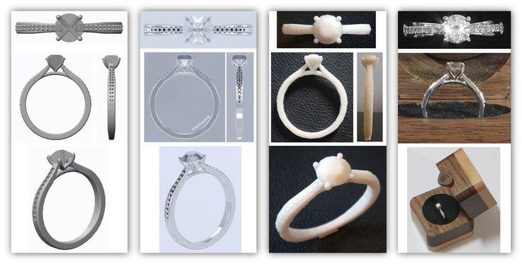 To learn more about this idea. Check out the “Local Miniatures and Islands” section in our tutorial video on “What the supports are for.”
There are three options for supporting your part:
- PreForm automatically creates a support structure based on the parameters selected for density and touch point size
- PreForm automatically creates the support structure and you can edit the placement, size and number of touch points using the Edit button on the support screen. PreForm will generate touch points as small as 0.3mm. Small sizes have the advantage of supporting small details without obscuring them, but they provide less structural support.
- You can create your own support structure in your model. The small and light design of the jewelry may allow the use of simplified supports, as in some of the ring examples shown earlier, with only one large support at the bottom of the shank.
Eliminating extra supports makes cleaning and surface finishing easier, but may mean the part is not fully supported.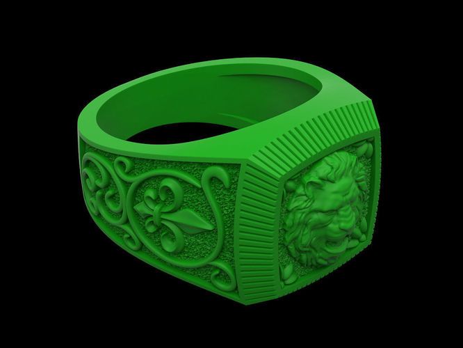 Experiment, try different settings, and get to know your printer.
One caveat must be made here: when printed parts are unsuccessful, they leave residue in the resin tank, and then the resin needs to be filtered and the tank cleaned to remove such particles and ensure no contamination for the next print job (read the document “Cleaning the Resin Tank”). resin” for more information) After you have done this procedure several times, it will not take too long. So don't use this as an excuse to stop experimenting!
Fig. 14.1: Fault in spherical ring when printing with PreForm.
Fig. 14.2: Spherical ring with hole facing up (or down in the actual assembly so as not to trap the resin), the bottom surface of the sphere shows slight deformation.
Fig. 14.3: Spherical ring with CAD support and base, "wrong" orientation due to the possibility of trapping the polymer inside the sphere, actually gave the best result.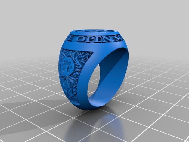
EFFECT OF ORIENTATION ON PRINTING
Printing success depends on how the parts are oriented during printing. For the simplest parts, orientation is less critical, but as parts become more complex, thoughtful and correct orientation becomes important. Be aware of the forces acting on each print layer: peeling and resin flow. When viewing a part in PreForm, the part is displayed on top of the build platform surface. The Form 2 platform prints upside down from the image shown in the PreForm.
There are two major hurdles to overcome this. First, printing large flat surfaces parallel to the build platform exposes these surfaces to significant peel and flow forces, and requires huge supports to print successfully. The simplest fix is to direct such surfaces in such a way that only portions of the surface are subject to printing forces at any given time. Second, hollow objects can trap resin if the opening of the object is oriented over the resin tray.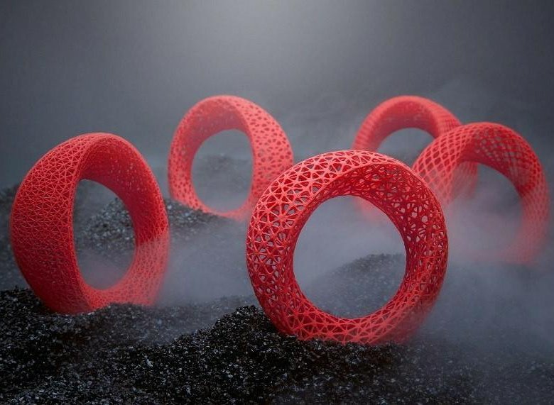 Once the hollow part is sealed, the polymer can be trapped inside, deforming the final surface and adding mass during the peel/flow process. The easiest solution is to orient your part so that the opening of the hollow object drops into the resin tray.
The following examples (fig. 14.1 - 14.6) show different orientations of the same part, in most cases against the rules. For the spherical ring, the PreForm automatic angular orientation (Fig.14.1) was chosen, but for the square ring, the PreForm angular orientation (Fig.14.5) gave the best results in terms of accuracy and surface finish. The flat-topped square ring parallel and close to the assembly surface is predictable and shows that the surface does not meet the requirements (Fig. 14.4), with artifacts of this mismatch adhering to the surface of the part. A square ring with a single support built into the array (Figure 14.6) was printed almost exactly as planned by PreForm and would have been easier to clean up. The most important thing to take away from these examples is the importance of experimentation in learning how to use your printer.
Figure 14.4: Square ring with flat face parallel to build platform, flat face does not meet requirements.
Fig. Figure 14.5: PreForm Auto Orientation Square Ring, Best Done
Figure 14.6: An irregularly oriented square ring printed perfectly, creating a closed container with opening pointing up.
Part orientation can affect how many supports are needed. Use the Slider tool in PreForm to make sure all model details are supported. In these first examples (Figures 15.1 - 15.3), the ring was at an angle with low support density, and four of the unsupported prongs were not printed. The setting of the emerald is set in an intuitive vertical position (Fig. 15.4), and you can see that the inner corner of the very delicate heart shape is missing from the gallery (Fig. 15.5 - 15.6). For such a small part, it would be impractical to add support to this corner, as the cleaning can never be completely completed. This could have been prevented with the Slider tool. As soon as we flip the emerald setting so that the inner heart points are supported by the previous layers, they print perfectly (Fig. 15.7)
Fig. 15.1: Angle ring.
Fig. Figure 15.2: Using the Slider tool in PreForm to view unsupported islands that will float away during printing.
Fig. 15.3: Ring printed showing incomplete assembly of upper large prongs due to unsupported islets.
Fig. 15.4: Setting the emerald in vertical orientation.
Fig. Figure 15.5: Using the Slider tool to make sure the inside of the heart shaped decor won't print successfully
Pic. 15.6: Seal of the emerald setting, showing that the inner points of the hearts are not printed. Also note that shrinkage occurs before and after the prongs are attached to the top bartack plate.
Another printing problem in this orientation can be seen where the prongs of the center stone are attached to the top frame of the bartack in both ring and bartack. Where the prongs are not attached to the shield, there is very little compression of the polymer due to the transition from a relatively heavy part to a much thinner part (Figures 15.6 and 15.8).
Fig. 15.7: The setting of the emerald is reversed so that the inner heart objects are supported by the previous layers.
Fig. 15.8: This ring was printed in a vertical orientation and shows the prongs shrinking before it is attached to the top bar of the bartack
part of the length of a thin prong is built as it meets
Fig. 15.9: The setting of the emerald is oriented so that the transition from thick to thin is minimized, which greatly improves the blending of the prong into the frame.
Fig. 15.10: The ring is oriented so that the transition from thick to thin is minimized, which greatly improves the blending of the prong into the frame.
MOLDING IN BRIEF
We have already addressed some of the issues with molding printed parts, but there are other considerations to consider when casting or outsourcing the printed part.
Where do you need a sprue or better question, where do you not need it? The sprue should be placed in a location that provides the best flow of metal into the mold and where it does not interfere with the structural components or make it difficult to clean the casting. If you are not sure where to place the sprue, ask your caster where they would like to place the sprue and discuss any problems with them.
What metal do you use for casting? Gold and silver are not problematic metals, but platinum is difficult to cast under the best conditions and even more difficult when casting polymers. When casting resins for platinum, most manufacturers recommend printing on a solid resin and then making a mold so the waxes can be used for casting (see our vulcanization documentation)
Even the best casters sometimes fail to successfully cast some parts. If your design is extremely complex, it would be a good idea to send an extra print in case the first casting is not successful.