What does cad stand for in 3d printing
SolidFace 3D CAD - SolidFace 3D CAD What does CAD stand for
Definition – What does CAD stand for?
Computer-aided design (CAD) is a computer technology that designs something and records the design’s process. The CAD may facilitate the making procedure by transferring comprehensive diagrams of a product’s materials, strategies, tolerances, and measurements with particular conventions for the merchandise in question. What does CAD stand for? It could be used to create either two-dimensional or three-dimensional diagrams, which, when revolved, can be analyzed from any point of view, even from the inside looking out. A particular printer or plotter is usually required for printing professional design renderings. CAD is also less-known as computer-aided design and drafting (CADD).
SolidFace explains Computer-Aided Design (CAD)
To make detailed engineering designs through 3-D and 2-D drawings of the physical components of manufactured products. To create concept designs, product layouts, strengths, and dynamic analysis of assembly and the manufacturing procedure themselves.
To prepare situation impact reports, in which computer-aided designs are employed in pictures to produce a rendering of the appearance when the new structures are built.
What does CAD stand for? CAD solutions exist today for all of the major computer platforms, including Windows, Linux, Unix, and Mac pc OS X. The interface mostly centers around a computer mouse, but a pen and digitizing visuals tablet may also be used. View manipulation could be achieved with an area mouse (or room ball). Some operational techniques allow stereoscopic eyeglasses to see 3-D models.
Many U.S. universities zero require lessons for producing hands drawings making use of protractors and compasses more. Instead, there are plenty of classes on various kinds of CAD software programs. Because software program and hardware expenses are decreasing, universities and producers train students on how best to make use of this high-level equipment now. These tools also have modified style workflows to create them better, lowering these teaching costs even further.
The CAD industry has been in motion and evolving for 60 years and will continue for 60 more.
What does CAD stand for? Sixty years ago, the “Creator of CAD,” Dr. Patrick Hanratty conceptualized the first numerical control system, which later becomes Computer-Aided Design or CAD. The preciseness, skillfulness, and edit-ability of CAD designs revolutionize the engineering, architecture, and manufacturing landscape. The importance of CAD cannot be contested.
What does CAD stand for? The History of CAD closely follows the “History of the Computer, ” there have been a lot of innovations and versions over the years. With its begin in 1957, it was still years ahead of small and affordable computers that could run the software. Pencil and paper would always be the primary tool “draftsman” would create designs for more than 30 years. But it was the base for things to come; CAD software would become a fundamental tool for nearly every industry.
THE OVERALL GAME CHANGER
During the 1970s, silicon chips and microprocessors let more powerful yet cheaper computers. Smaller design companies could begin to access the technology and were able to spread out operations leading in a boom of production and design applications. Some of the features of CAD/CAM now days are only improvements with modeling and additional data set analysis from conception and engineering to the manufacturing process. By updating the operating systems, the goal of CAD/CAM developers now is to refine the system to become faster and more user-friendly.
CAD BRAND TIMELINE
PRONTO 1957 Built by Patrick Hanratty, this is the first commercial numerical-control programming system, sparked precisely what is CAD.
Sketchpad 1960 Built by Ivan Sutherland, this is the first to work with a total graphic interface, making use of a light pen on an x-y pointer display, it allowed users to constrain properties in a drawing, created the usage of “objects” and “instances.”
ADAM 1971 Built by Patrick Hanratty, this graphical design, manufacturing, and drafting system was written in Fortran and made to work on just about any machine, a big success that continued to be updated to focus on 16 and 32-bit computers, today 80% of CAD programs could be traced back again to the origins of ADAM.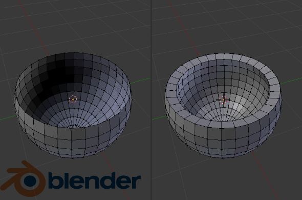
IGES 1980 allowed users to transfer their 3D designs between CAD software packages, once STEP premiered IGES anymore didn’t get updated.
CATIA 1981 by Dassault Systems – Multi-platform CAD software, today still in use.
AutoCAD 1982 by Autodesk, this is the first 2D design CAD software designed for PCs rather than mainframe minicomputers or computers.
Pro/Engineer 1987 Now PTC Creo, this is the first mainstream CAD tool that took the concepts of Sketchpad (Interactive, easy to use, fast) and made it more realistic, based on models, history-based features, and the use of constraints, this was an immense turn in CAD history, it entirely knocked out any competition, others were coded in Fortran and assembler, this was coded in UNIX’s X-Windows which made it more precise, robust, and faster.
STEP 1994 Changed from IGES as the new file extension to use when migrating 3D models from one system to another, 1994 was the first of STEP that made it a global standard for models, in 2019 still is the most common file format.
SolidWorks 95 1995 by Dassault Systems – Another software that succeeded in ease of use, allowed thousands of engineers to start using 3D CAD technology.
Solid Edge 1995 by Siemens Made as a response to SolidWorks initially a PLM software (Product Lifecycle Management), native from Windows, had solid modeling, assembly modeling, and 2D orthographic view.
SolidFace 2013 A industry direction, tried to be more intuitive and straightforward, also allowed the creation of simple and complex collaboration in part and assemblies we really upped the game in the CAD world.
Future of CAD Software
CAD technologies are rapidly evolving, with constant developments. These applications are growing necessary in various areas and for more and more different forms. This expanding use of CAD leads to new developments. Indeed, these CAD tools have to be adapted to the latest methods and modern users they’re targeting.
What does CAD stand for? Do you know the fundamental changes that folks using CAD software want? And what could possibly be achieved later on? Let’s notice what the brand new significant trends are usually and which CAD software program functionalities could be remarkably improved in the forthcoming years.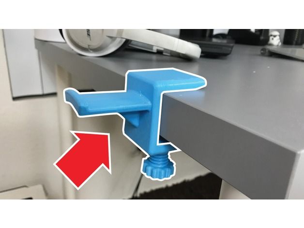
The Evolution of the usage of CAD Software
What does CAD stand forThe B2B software world rapidly is evolving. The benefits of 3D CAD are usually unlimited; in fact, it is a real game-changer for several companies that are utilizing it to improve their work, products, or services. Companies are not applying 3D modeling software for the same purposes. There are several ways to create the majority of CAD software: gaining a better visualization of a task, rendering, 3D publishing, simulation, and prototyping to provide some examples.
For the medical field, CAD software can be handy to get a precise visualization of a new nagging problem. It could be used, for instance, before medical procedures to look for the best technique to adopt. This is an excellent device for simulation also, so as to start to see the result of possible surgery. Those visualization mechanisms are also used efficiently in architecture or mechanical engineering. It is now necessary to get a useful and detailed overview of the project.
CAD programs are now used not only by designers, but also engineers, researchers, surgeons, and several other professionals. This is why software manufacturers are changing and enhancing features, and as new developments are appearing, we have been starting to start to see the form of the continuing future of CAD software.
Do you know the Next Developments for CAD application?
The growing usage of CAD software results in new trends and recent evolutions. Let’s discover what will be enhanced in the upcoming yrs for these programs.
Automation and Artificial Intelligence
One of the most significant trends these ages is unquestionably automation. We can see it in many areas, thanks to the advancement of Artificial Intelligence. It will be more and more present with 3D modeling software. Certainly, CAD applications can anticipate our activities and improve our 3D modeling experience, allowing users to repair or plan design errors.
Automation will significantly increase your work and enable us to bypass 3D modeling obstacles. Thanks to AI, these applications will progressively become more intelligent. Some software companies are already beginning AI in their methods, and it will be even more common in the upcoming years, allowing them to automate design tasks. It will create new quality control features, generally improving the continuous function and products of businesses focusing on these programs.
Some CAD companies already unveiled a new version by using these automation technologies. The company’s CEO is claiming that automation may be the future of design.
On its side, others developed new tools making use of AI and automation furthermore. Dream Catcher can be a valid program, for example. They are allowing users to focus on regenerative designs, with the ability to generate a vast selection of designs in just a few hours.
Cloud-Based Software
What does CAD stand for? 3D modeling software might have some constraints: These 3D programs were previously quite complicated, concentrating on only one computer. Now, with the increasing usage of what we contact the cloud, a lot of applications and software are cloud-based. CAD software can be accessed from wherever around the globe and don’t need any connection process: they are called SaaS, or Software-as-a-Service.
The shift to SaaS is changing the way we can collaborate and work. CAD users need better collaboration with their teams. That is why SolidFace cloud is now so essential. It is enhancing the partnership since it allows several people to focus on the same document. Extended collaboration will be something important now, improving teamwork and efficiency.
Cloud-structured CAD software was something unimaginable a couple of years ago just. Now, they’re spreading! For instance, Onshape is by using this cloud-based technology and can avoid problems plus crashes associated with license keys plus compatibilities. When using a cloud-structured CAD plan, you don’t have to worry about information or upgrades management as you obtain a universal usage of data.
These programs may also be allowing the analysis of some data: Who done the model? Just how long did it try to finish this? Some cloud-based software program tools enable these analyses and may improve workflow.
These cloud-structured applications have massive advantages undeniably, and they’ll become more and much more present accessible in the coming years.
Virtual Reality
The gap between 3D CAD and reality could become thinner while using CAD software. Visualization and rendering are improved continuously.> CAD software tools need to get proper 3D tools for these functionalities, to get 3D models closer to fact and achieve the best preview feasible of the project.
Now, the case of visualization is going further: Virtual fact claims will soon become standard CAD software functionalities. Some 3D designs can be viewed as if they existed in a physical space, thanks to virtual reality helmets. This could be especially useful in sectors like architecture, and some software program markers are needed to create the compatibility of this software with 3D looking at equipment.
New options regarding digital reality could possibly be unveiled inside the upcoming years, as these technologies seem promising for a number of different industries, really.
Solid Specialization or Personalization Possibilities
What does CAD stand for? Another aspect of making 3D software fascinating for companies may be the way these applications can fit the consumer’s needs. That is why we can achieve more specialization increasingly in the CAD globe. >There are a lot of 3D programs dedicated to specific sectors like electronics, architecture, and cinema. This way, CAD users have the CAD tools and features they need to work on their project, as these scheduled applications are made for a particular use.
Customized CAD
Before choosing your 3D modeling software, you shall consider the most readily useful tools for you are. Do you want a software dedicated to chemistry, jewelry, or character design? CAD specialization is now essential for the companies, and it is not going to stop now!
CAD software could be more customizable, and customers may have a facilitated usage of the features and equipment they utilize the most, or which will be more exciting because of their projects.
We can say already that development <will intensify in the upcoming years. Indeed, all the different sectors and users might need various features. There is a growing importance for personalization. Users now want to augment and configure their work environment, and they need to optimize it to use the best tools for them. The main goal is to quickly design and custom products, thanks to software adapted to the user. These advanced platforms need to be personalized, once again, to improve the daily work of the user.
As you can view, the universe of CAD software is developing fast, and the primary purpose of all these trends are equal: improving the user’s work. We now know these functionalities will grow and be quite reasonable in the future years quickly. We believe you require some insight into where the CAD software program heading now. So start following us to see what SolidFace is bringing to the industry.
What does CAD stand forProblems SolidFace is trying to solve in working with CAD Interoperability Today.
For more than forty years, CAD has served numerous designers to innovate and deliver exciting products to life. The software industry for CAD is expected to rise in 2019. But with the CAD software program businesses’ success, there’s an apparent shift happening with techniques products are developed. Marketplace trends are usually shifting to a scenery <where the authenticity and reach of CAD tools are falling low to some degree.
With disruptive technologies like 3D printing and cloud computing, there is a crowd of community makers, hardware startups, and personal technology product manufacturers. This quick development has led designers to democratize, beginning the use of multiple CAD systems in the design process, and attacking the CAD interoperability.
You have many suppliers who work on their CAD platforms, and then you have a few different 3d modeling solutions within your organization. Merging this democratized CAD data without changing the design intent is inherently sensitive.
To know why it is problematical, you need to comprehend and understand how the CAD system stores the data.
Most contemporary CAD software uses almost similar data representations. There are assemblies at the top, with parts beneath and different drawings. The components are described either parametrically or making use of their topology defined making use of boundary representation (B-rep) solid design explicitly, comprised of NURBS (Non-Uniform Rational Base Spline) surfaces. These areas are usually tightly knitted with one another using tolerance information to help make the geometry watertight.
What does CAD stand for? Now, the most significant problem with different CAD systems is differently that different software handle tolerances. Frequently, when translating the file in one order to some other, the receiving program misses out a few of the thresholds, producing a design with holes or gaps. The model will often come in the <form of surface patches, which you then toss with and see if the program can suture those surfaces into a solid model.
What does CAD stand for? The cause why CAD systems have permission issues is primarily because of the imprecision present in the mathematical algorithms written for geometric modeling kernels. Even more, native CAD files further increase the complexity, as every CAD system considers surfaces and topology differently. Standard types such as IGES and Stage have their own problems. Since they are open up, anyone can try to write data files in the format, whether proficient or not, really, causing a chance of a large number of mistakes.
The MBD Trend
What does CAD stand for? They are throwing more fuel to the interoperability fire, maybe the recent Model Structured Design (MBD) style that is rising to define product making information accurately. The idea behind MBD would be to embed all of the manufacturing information straight onto the 3D versions, eliminating the necessity of 2D drawings. Although some large aerospace companies have adopted this process to get benefits in minimizing price and wastage, it’s been only 2-3 years that this idea has obtained traction outside this business.
MBD transforms CAD interoperability significantly, as it sums another coating of data to the 3D CAD files. The translator now also needs to handle all the commentaries as nicely apart from its usual task of deciphering the geometry.
To conclude some typically standard Merchandises designed using CAD
What does CAD stand for? Nowadays, CAD software is so universal that it could mainly be more comfortable to count the list of products that were not designed using it. CAD now has control in fields as diverse as home appliances, consumer electronics, and furniture. Below, we’ve selected a few types of items designed using CAD.
IPOD
Presumably, the most ubiquitous styles of the 21st century, Jonathan Ive‘s design for the original iPod, sparked a revolution in the exact way we consume music. Its friendly manner signaled a significant departure from the cluttered songs participants that defined the marketplace in the first 2000s, and, crucially, had been both easy to use and engaging to own.
Tip Ton Chair
In 2008, designers Barber & Osgerby were requested by the Royal Culture of Manufacturers and Arts, who needed recommendations about furniture for a second college in Tipton, England. Barber & Osgerby saw a chance to produce a brand-new type of chair that could aid focus while allowing both great design and value. The Tip Ton chair was consequently born, allowing forward tilting and different seating positions without requiring any moving parts. Barber & Osgerby also took into the record the school environment and created a practically indestructible, stackable, and easy-to-maintain chair. View the Tip Ton chair’s CAD data here.
Louboutin fragrance bottle
British designer Thomas Heatherwick‘s designs have varied in scale from the 2012 Olympic cauldron to his range of spinning top-esque stools, Spun. He’s also worked beside the Christian Louboutin fashion house to create a unique fragrance bottle. Heatherwick intended to subvert the standard form of a fragrance bottle by putting a hole in the center of a rectangular container. The design was motivated by the belief that “liquid is alive,” with liquid flowing around the bottle, while it also evokes gentleness, personality, and sexuality.
Lily light
Janne Kyttanen‘s Lily light, created for the Freedom of Creation studio, was deeper than just a nice lamp-although. It was undeniably aesthetically appealing. It also meant the first product outcome to demonstrate the opportunities offered by 3D printing in the field of interior design. At the time, 3D printing was an extraordinarily expensive manufacturing machine. Kyttanen’s task, consequently, was to produce a significant impact with a small light, while making sure the finished product was commercially possible still.
Polder Sofa
Created by Hella Jongerius within 2005, the Polder Sofa is really a playful, unique style that eschews the symmetry connected with sofa design typically. Rather, it opts for an irregular style, divided up by rigorous lines, which is designed to reflect the looks of the Dutch scenery from the bird’s eye view. It is possible to explore the CAD information for this task yourself at Vitra.
What is CAD? Definition, Advantages and Uses Explained
Computer-aided design, more commonly known as CAD, is the use of computers in the design process across a wide range of different industries. It is primarily used to create highly accurate 2D and 3D models, but CAD covers all steps in the design process, from creation and modification to analysis and design.
- We also have a ranking of the best CAD software.
CAD is a vital tool as it improves designers’ productivity, quality, and communications, and it can also be used to create a database for manufacturing. CAD software makes it possible to visualize properties such as height, width, distance, color and material, and also to build entire models for any application.
Architecture, construction, engineering, 3D printing, carpentry, and metal fabrication are just a few of the many industries that use CAD. Computer-aided design and drafted (CADD) is a less commonly used variant of the name.
- We also have a ranking of the best architecture software.
That’s a basic rundown of CAD, but there’s plenty more to learn about this important technique. This guide covers everything you need to know about CAD, including its advantages and disadvantages, how CAD works, and its applications.
What is CAD – the Basics
CAD is used to create precise drawings and models of objects and structures, either in 2D or 3D.
CAD was developed as a more accurate, affordable way for designers, engineers and manufacturers to design, visualize and test models while minimizing the chance of mistakes.
As CAD allows for easy modification, documentation and collaboration, it is a far more precise, efficient and faster method than traditional manual drafting. Today, CAD has replaced manual drafting across a wide range of industries.
CAD software takes into account how the various materials involved in a project interact, allowing designers to consider every element in a project, from plumbing to electricity. This results in fewer revisions and a more efficient workflow.
Today, CAD software incorporates cloud technology, providing entire teams with instant, remote access to projects. These advantages mean CAD has had a huge impact on architecture, engineering, and construction, among other industries.
There are many types of CAD software out there, and while they all operate differently, all are based on geometry. Every CAD program has X (horizontal), Y (vertical), and Z (depth) coordinates which allow users to create 2D or 3D models. CAD programs typically use either vector-based graphics or raster graphics to represent drawings and models.
As well as expensive paid-for CAD software used by professionals, there are also free programs that are better suited to students and hobbyists. For example, While AutoCAD is the industry leader and is used by professionals across a wide range of sectors, Blender is a high quality free CAD software that is available to anyone.
CAD History
The early origins of CAD can be traced back to the 1940s and 50s, when various developments made in computer software widened the design-related capabilities of early computers. The term “computer-aided design” was coined in 1959 by MIT researcher Douglas T. Ross.
A turning point came in 1963, when computer scientist Ivan Sutherland developed the world’s first computer graphic program, SKETCHPAD. This program allowed people to graphically interact with a computer by drawing directly onto a CRT monitor with a light pen and marked the beginning of CAD software as we know it.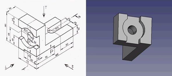
It wasn’t until the 70s when CAD began being used in industry rather than simply for research purposes, as large automotive and aerospace companies began developing their own software. The CAD program CATIA was developed in 1977, and another major milestone came when John Walker founded Autodesk in 1982.
CAD software continued to grow throughout the 80s and 90s, although it remained restricted mostly to larger companies during this time. CAD became more accessible as personal computers rapidly spread in popularity in the late 90s and 2000s, leading to the development of open-source CAD programs that are available to everyone.
2D & 3D CAD
CAD can be used to create both 2D drawings and 3D models. Some CAD software specialize in one or the other, while other programs are capable of producing high quality 2D and 3D designs.
2D CAD models are flat, two-dimensional drawings and provide the information, such as dimensions and layouts, needed to reproduce or build the subject.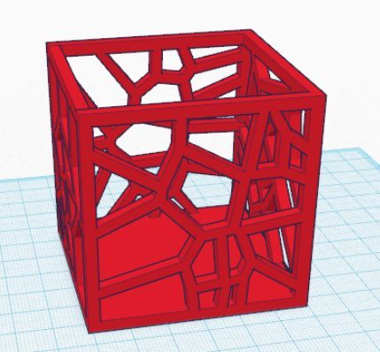 These 2D models are commonly used in industries such as architecture, civil engineering, automotive, interior design, landscaping, cartography and fashion.
For example, CAD software is used by architects to create floor plans of buildings and houses, and these floor plans contain most of the information that would be needed to construct the inside of the building. As well as floor plans, CAD can be used to create technical drawings and blueprints, piping and instrumentation diagrams, HVAC diagrams, site and plot plans, electrical schematics, and wiring diagrams.
3D CAD models have similar uses to 2D models, but they provide more detail about the individual components and assemblies of physical; objects and structures. So, 3D models better show how subjects fit together and operate. CAD can be used to create 3D models of almost any kind of structure or object, from buildings to aircraft.
These 3D models are therefore used in a wide variety of industries, such as for creating intricate visualizations in the automotive and manufacturing sectors.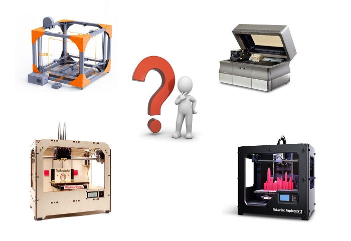
Advantages of CAD
There are a range of benefits that make CAD such a valuable tool across multiple industries. Let’s take a look at the main advantages of CAD.
Accurate, high quality visualizations – The main advantage is that CAD software allows you to visualize designs and projects by creating highly accurate, lifelike 2D and 3D models. It allows for far more accurate designs than physical drawings, making it easy to create complex shapes and surfaces, and it also provides a wide range of tools for creating high quality, visually pleasing drawings and models. This is vital for designers as it allows you to fully test and alter models before bringing your digital design to life in the form of a physical object.
Revisions – CAD allows you to make as many documented changes as you need to your designs in a much easier way than if you were using a pencil and paper. Instead of having to go back to the drawing board if a design doesn’t function as expected, CAD makes it easier to identify errors and solve them before prototypes are made, giving more quality control power and saving both time and money.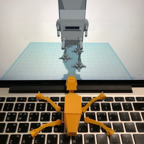 The best CAD software can even run simulations to test for any problems.
Increased productivity – Designers using CAD can work faster, smarter and cheaper. This is because it removes the need to draw everything by hand, makes for easier edits and allows for accurate testing before developing a prototype. This allows for more efficient work, which in turn means companies can employ less designers, making for an all-round quicker and more affordable design process than traditional methods.
Collaboration – Many designers work as part of a team, so collaboration is key. CAD software makes it incredibly easy to instantly share designs with your colleagues, both in-house and remotely, and each team member can view the design history so that every stage in the process can be worked on collaboratively. Many CAD programs now use cloud technology, so that designs are accessible at all times and don’t even need to be manually shared.
Documentation – CAD software documents every part of the design process, including measurements, angles and dimensions.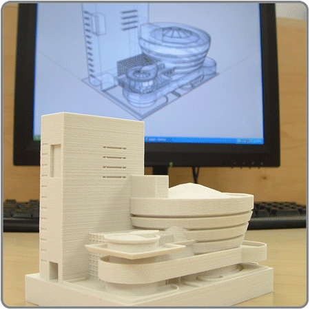 These properties can be easily reused in future projects, and you can also easily save components and subassemblies for futures designs.
Easier to understand – 3D models can be much easier to understand and comprehend than complex physical sketches. Whereas physical sketches require plan, elevation and side views, CAD software can easily create standardized, organized models and drawings that are easy to understand even to colleagues without a background in design or engineering. This also means that CAD models can be used in marketing and sales pitches to clients as they look impressive and clearly demonstrate the aesthetics and functions of a design.
Realization – As well as improving the design process, using CAD can also accelerate the manufacturing process. By using compatible computer-aided manufacturing (CAM) software, you can easily check the tool paths for CNC machining and input the files in the machines. CAM software creates the required machine code for production based just off the CAD model, providing a much more efficient method than traditional manufacturing processes.
Specialization – CAD is used across a wide variety of industries, and there are specialized programs for almost every sector. This makes it a widely applicable technique.
Disadvantages of CAD
While there are many benefits of using CAD, it isn’t without limitations:
Price – The best CAD software can be costly – thousands of dollars in some cases. This isn’t a problem for companies that are able to save on the cost of the additional team members that would be needed without CAD, but it does mean the best software may not be accessible to beginners and hobbyists.
Hardware – High quality CAD and CAM programs typically require powerful hardware for optimal performance. Again, while this isn’t a problem for larger companies, this expensive hardware isn’t always accessible for individual designers using CAD.
What is CAD Used For?
We’ve already touched on some of the many applications of CAD, but now let’s take a more detailed look at some of the most common and significant uses of CAD software.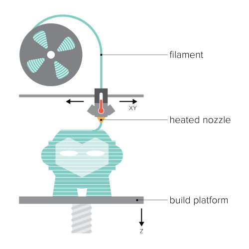
Architecture
Architecture is heavily reliant on the creation of complex yet highly accurate drawings and models, so CAD is an invaluable tool to architects. CAD is also useful to architects as certain software, like Revit and ArchiCAD, use BIM workflows to improve productivity. BIM (building information modeling) is a 3D model-based process that allows for more efficient design and construction in architecture projects by incorporating intelligent automation and collaboration tools.
Engineering
CAD is a valuable tool to engineers as it allows them to perfect their designs before building prototypes, and they can also simulate designs to test stress levels, fluid flows and tolerances of projects, among other factors.
It’s used across a wide range of engineering fields, including buildings, infrastructure, telecommunications networks, electrical circuits, thermodynamics and mechanical parts. Like in architecture, engineers use BIM CAD software to help improve structural fabrication, minimize errors and streamline collaboration.
Product Design
CAD software such as Inventor and Fusion 360 help industrial product designers both visualize objects and understand how they will function. For example, CAD is used in car design to conceptualize and render automotive designs.
Graphic Design
Similarly, 2D and 3D CAD software is used by professional graphic designers to create visualizations, as well as add effects, shapes, typography and backgrounds to their visuals.
Construction
In construction, CAD software can be used to simplify blueprints and provide uniform measurements, as well as making adjustments when the project is in process. It can also digitize construction sites and link project information from design to construction.
- We also have a feature story on 3D printing in construction.
Other Applications
CAD is also used for the visualization and design of products in a wide variety of other sectors, including city planning, animation, metal fabrication, carpentry, fashion, interior design, game design and manufacturing.:quality(90)/images.vogel.de/vogelonline/bdb/516000/516072/original.jpg)
- We also have a ranking of the best animation software.
Manufacturing from CAD
While CAD is used in the design process, it can’t be used to actually create physical objects and structures. For that, you need to use a computer-aided manufacturing (CAM) program along with a manufacturing machine.
CAM uses numeric control software and encodes automated instructions for a machine, such as a 3D printer, CNC router or laser cutter. The best results are achieved when both CAD and CAM are used together, as they provide much more control over the entire process from conceptualization through to realization.
Using CAD
As we’ve previously covered, the availability of high quality free CAD programs means that it’s available to everyone, regardless of budget. That being said, there are a few things you should consider before getting started with CAD yourself.
Firstly, you’ll want to check the number of cores and threads your computer processor has.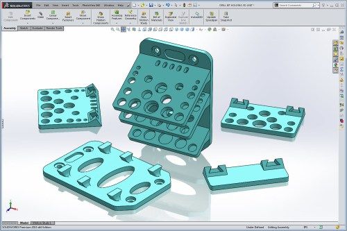 Some CAD software are best used on processors with multiple cores, while other programs can’t handle them, so knowing this will help you find the best CAD tool for you.
You’ll also want to make sure that you have sufficient random-access memory (RAM) so that you’ll be able to multitask efficiently, like rendering or working with multiple programs at the same time. You should also check that you have a sufficient graphics processing unit (GPU). Your computer’s graphic card is what makes CAD visualization possible, so having a high quality card like a Nvidia or AMD will help you get the most out of your CAD program.
Finally, remember that not all CAD programs are compatible with all operating systems. While some run on Windows, others are only available on Mac, and not every CAD software is available on mobile operating systems.
What is CAD? Conclusion
CAD refers to the use of computers in the design process of objects, structures and buildings. It’s primarily used to create highly accurate 2D drawings and 3D models, but it covers every step in the design process, from conceptualization to testing.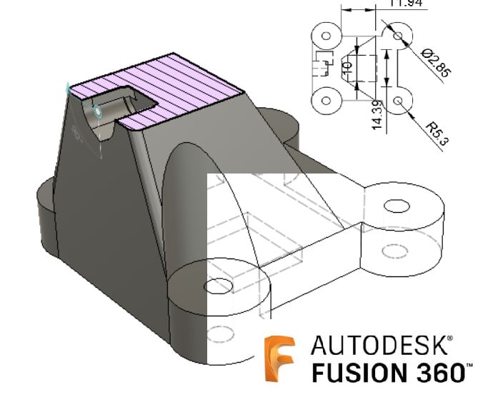
CAD has a wide range of advantages, including high accuracy, unlimited revisions and increased collaboration, that make it valuable to professionals across a wide range of industries, particularly architecture, engineering and construction. There are both paid and free CAD software available, meaning it’s accessible to beginners and hobbyists.
CAD is constantly evolving, with every new version of a particular software bringing new updates and features. Both free and paid programs are becoming more powerful each year, and some tools, such as Autodesk’s Dreamcatcher, are even incorporating AI to further improve the quality and efficiency of the design process. As CAD programs become more advanced, they will open up more possibilities to designers and engineers and become even more important to an ever increasing range of industries.
short tips for the transition from a CAD model to a printed object / Sudo Null IT News
was withdrawn from publication due to a technical error.Please be understanding. Thank you!
Whether it's just a hobby or a source of income, 3D printing is always based on product design. Those accustomed to traditional technologies will have to rethink the entire approach to product design and manufacture.
When the project is ready, a number of additional operations are performed: setting the orientation of the model and other parameters that ensure the proper printing process. In addition, it is necessary to take into account the fact that most 3D printers allow you to choose the degree of filling the model with cellular structures. The correct choice of this parameter provides protection of the object from deformation and destruction during the printing process, as well as significant savings in material and reduction in production time.
Finally, the last factor influencing the success or failure of the 3D printing process is the strength of the connection between the model and the table. If the workpiece is separated from the table during printing, then all the work will go down the drain.
Here, we'll walk you through the 3D printing process and give you some simple tips on how to use additive manufacturing in the design phase. In addition, we will dwell on the methods of preparing a finished project for printing, and also consider ways to securely fasten the workpiece to the table.
These guidelines apply primarily to Fused Deposition Printers (FDM) printers, but may apply to other types of printers as well. The process of obtaining a finished part by 3D printing is basically the same regardless of the method used.
Designing an object
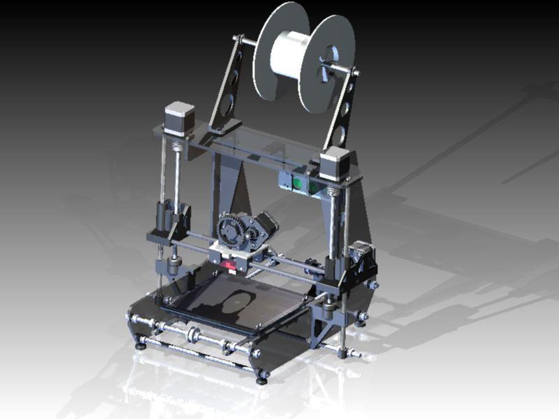
Any 3D printing starts with construction. If you are developing a product yourself, then you need to build a 3D model of it in a computer-aided design (CAD) system to turn the designer's idea into reality. In this case, the object can be both very simple and very complex. However, too thin and too small models should be avoided.
3D-CAD from Siemens from this article for 49900r (90% discount), the promotion is valid until March 20, 2020. Read more>>
Saving the file in a special format for printing
To print an object, its model must be saved in a special file format - for example, STL, which has become the de facto standard in the world of 3D printing. In this format, model surfaces are represented as a grid of triangles. Simple surfaces are broken down into a small number of triangles. The more complex the surface, the more triangles you will need. Today, other formats are used in 3D printing, in particular, the 3MF format developed by Microsoft. But the most common is still STL.
CAD systems make it very easy to save the model in the desired format: just click the Save As command. To improve print quality, it is desirable to set a number of settings for saving to the STL format - for example, the tolerance during transformation and the angle of the plane.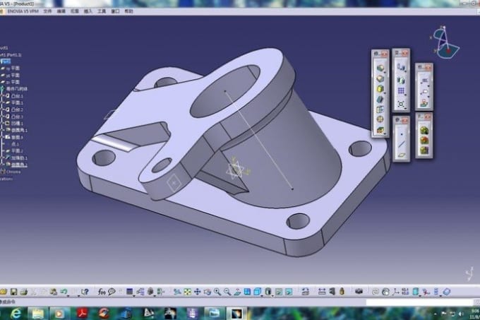 The lower the conversion factor and the better the angle, the smoother the printed part will be.
Opening the file in the slicer program
Most, if not all, 3D printers come with their own slicer software. The slicer loads the STL file created in the CAD system and cuts it into layers, and then creates a control program for the printer.
Place the model correctly in the print space
After entering the print settings, the model (or several models) needs to be placed on the printer table. You can print many objects on one table at once. At the same time, compared to printing a single object, the time slightly increases, but in general it still turns out to be less. Here are some tips for choosing the right model orientation.
Set parameters
In the slicer program, the user sets parameters such as print speed, material consumption, nozzle and desktop temperatures.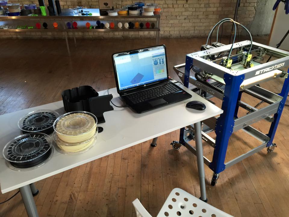 Most slicers have simple settings for beginners. In this case, most often there are also advanced settings so that experienced professionals can achieve optimal results. Advanced settings include percentage infill, amount of backing material, and type of backing or raft (this is a small, thin base that keeps the printed part stable. The backing is removed when it's finished). The number of options is truly endless. Specific settings vary depending on the brand of printer. It's easy enough to set them up.
Sending the control program to the printer
After setting the print settings, the placement of future objects on the table, their orientation and quality, it's time to finally start the printer. It is enough to press the Print button and find something to do while the production is in progress. Depending on the complexity of the design, the process takes from several minutes to several hours.
Finishing
Finishing includes removing the printed part from the table, as well as removing the support material by melting, mechanical separation or dissolution (depending on the design of the printer).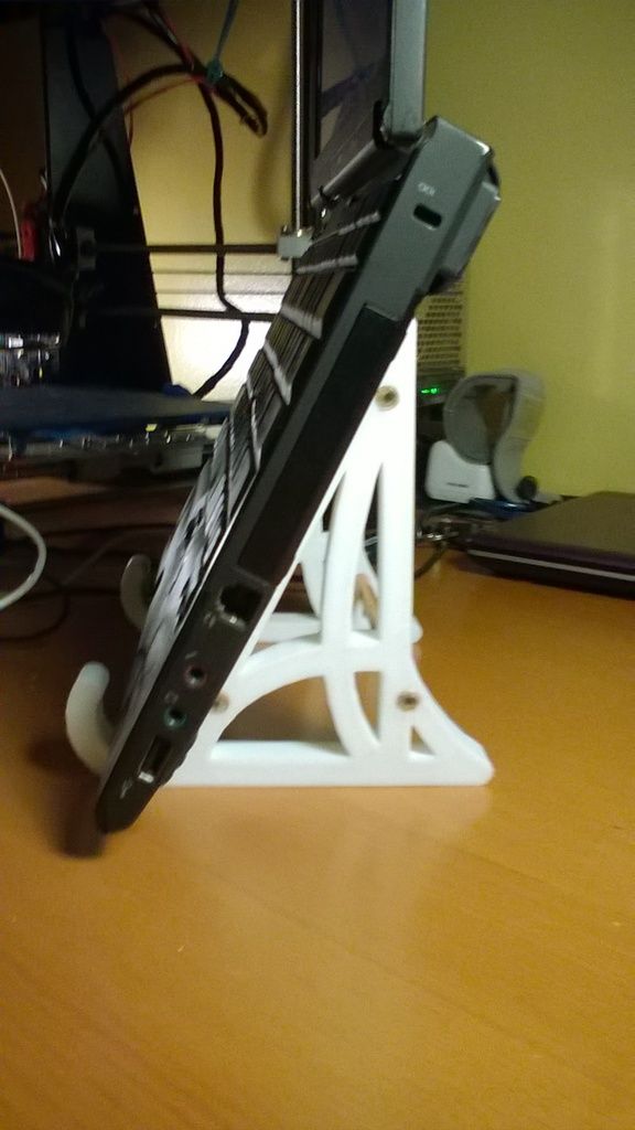 The part may require some light sanding or polishing, but overall a properly printed object looks good from the start. Other types of finishing are placing plastic parts in a container with acetone to smooth out surface roughness, gluing (if the dimensions of the structure exceed the dimensions of the 3D printer or individual elements of the object must have different orientations), drilling holes and painting.
3D printing process
3D printer design considerations
Eliminate sharp corners
If the direction of the surfaces changes abruptly (for example, a vertical wall intersects with a horizontal overlap), then such a model is difficult to print. The printer will build excessive inner surfaces, wasting too much material. There are two easy ways to prevent this: add chamfers to smooth out where the surfaces meet, or round the corners so the printer gradually builds a vertical surface. In addition, rounding will increase strength, since destruction most often occurs at sharp corners.
Elimination of thin walls and small geometries
Layer by layer fusing technology consists in supplying hot plastic through a nozzle with the formation of a printed object layer by layer. The thickness of the extruded plastic layer cannot be made smaller than a certain limit, depending on the diameter of the nozzle and the speed of the print head. Excessively thin-walled details are difficult to print - often the result is a chaotic weave of fibers. If the part can be printed, it is very fragile and breaks easily.
Too thick walls - also bad
On the other hand, if the walls are too thick, they become brittle and crack easily. This is especially important when printing from materials other than resins, as excess thickness during the manufacturing process leads to internal stresses in the part.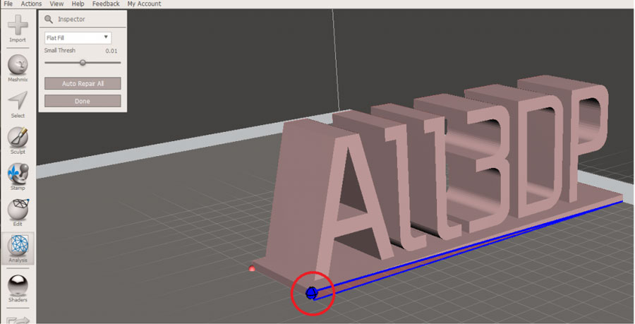 Even when printing from plastics, material is wasted on walls that are too thick and time is wasted.
Removing large overhangs
3D printers allow you to create amazing shapes and surfaces, but they are not capable of printing directly in the air. If there is a void in the part with material above it, additional support material must be used. Most slicers add material automatically, but require you to specify the orientation and volume of the support structure. Printers with a single nozzle create an array of thin columns, which then have to be broken off. The result is an uneven surface. Therefore, it is recommended to avoid large overhanging elements whenever possible in order to reduce the need for support material.
If such an element is unavoidable, you can try to flip the object. Most printers are capable of printing overhanging elements with an angle of about 45 degrees. At a certain height, the edge of such an element may sag somewhat.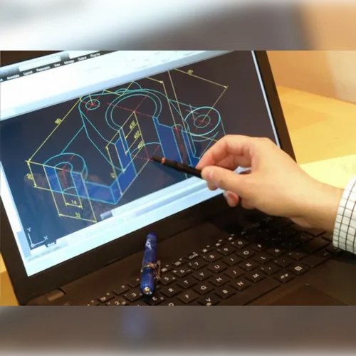 The actual capabilities of a particular printer are determined by trial and error.
Holes shrink
Remember that the part is made of heated plastic. As it cools, it inevitably shrinks. Therefore, holes and other critical structural elements have to be made larger so that after shrinkage their size is as close as possible to the required one.
However, if you need to make a tight tolerance hole, it is better to print it with a smaller diameter and then ream it with a suitable tool. This is especially true for holes whose axis is parallel to the printer table.
Increasing the footprint
If the area of contact between the object and the base is small, the part may separate from the table during printing. To prevent this from happening, wide bases are added to the model legs, which are installed on the printer table. In general, the closer to the table, the more material must be added to the support.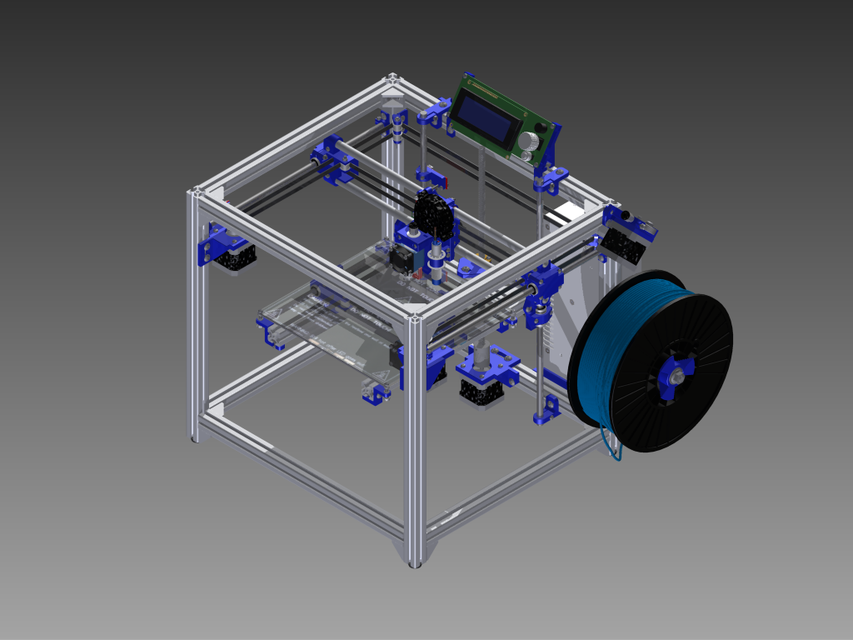 There are other ways to securely fasten the part to the table, which we will discuss a little later.
Special moves
The right approach to design makes printing easier. In addition, there are special post-processing techniques that are important to be aware of.
Place round surfaces vertically
The model should be oriented so that the minimum amount of support material is used. Ideally, it should rest on the table with a large flat edge. In addition, circular geometry must be placed so that the circular faces are vertical. If we look at the printer table from above, we should see a round silhouette of the object. In this case, the part comes out as symmetrical as possible with the formation of a solid round structure.
Place voids and holes vertically
If there are voids in the model (for example, it is a rectangular pipe), it is desirable to place such voids vertically in order to reduce the volume of the support material. If you print the pipe in a horizontal position, you will have to provide support for the entire interior. If you put the pipe on the end, then no support is required at all.
The same is true for holes: to get a hole with a straight axis, it is best to print it vertically - in the form of a stack of rings, which avoids warping or deforming a round hole into an oval one.
Set print quality settings
Proper selection of print parameters, such as STL conversion tolerance and slicer software settings, allows parts to be produced with a surface quality that matches that of cutting. However, this entails an increase in print time. When choosing quality parameters, one should proceed from the purpose of the object: is it a finished product or a prototype? Will the part be visible or hidden?
The quality parameters also affect the shape of the holes in the part. In CAD files, holes are represented as a set of straight lines at an angle to each other.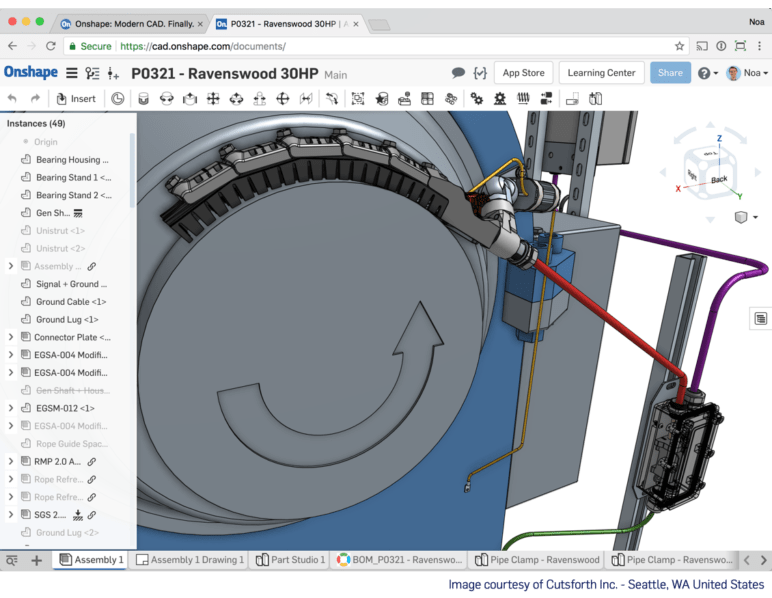 The higher the quality of the model in the saved STL file, the less the circle looks like a polygon.
Reducing the layer thickness
To obtain the best quality, especially when using layer-by-layer deposition technology, it is necessary to reduce the thickness of the layers. It does increase the print time, but the end result is worth it!
Optimizing the filling with honeycomb structures
In terms of strength, objects do not have to be solid. Similar to a honeycomb, printers can create a honeycomb infill that balances strength and saves expensive polymer material. However, if the printed part serves as a prototype for strength testing, and the serial product will be manufactured by traditional methods, and also if the part is subjected to certain types of mechanical stresses and pressures, a solid design will be preferable.
Choosing a material
The success of printing largely depends on the correct choice of material.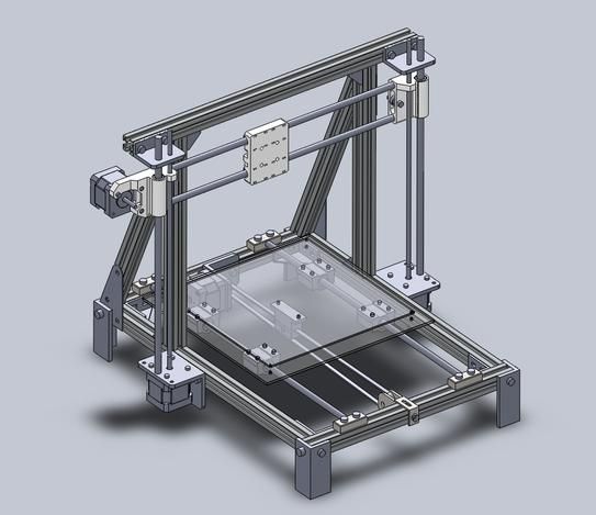 Materials have different properties. For example, the melting point of thermoplastic polyurethane (TPU) and polylactic acid (PLA) is lower than that of acrylonitrile butadiene styrene (ABS). In addition, the material is taken into account when choosing the type of support structures. For an object made of polylactic acid, supporting elements can be made from the same polylactic acid, since it will be quite easy to separate them from the finished part. If the part is printed from ABS plastic, then the support elements must be made from a different material, and it is better not to use such elements at all in thermoplastic polyurethane parts.
Cellular filling
A solid body is not always the best choice for 3D printing. Printing solid parts has its advantages, but the internal honeycomb structure saves both expensive material and time.
Creating objects with a specified degree of filling with honeycomb structures is a unique opportunity for 3D printing. Moreover, it is not required to design such a structure: this is done by the slicer program. As a rule, it is enough to set only the percentage of filling (the closer it is to 100, the more solid the object will turn out) and select the type of cells, if the printer has such an opportunity.
In addition to saving time and material, the internal honeycomb structure has many other advantages.
Cellular filling prevents warpage
Printing large objects as a single piece introduces a danger of warpage. By reducing the infill percentage, the air during printing passes through the part, providing more uniform cooling and eliminating warpage.
Cellular filling does not lead to loss of strength
Printing cells instead of solid material does not reduce the strength of the part. In many cases, a honeycomb part is strong enough for the chosen application, but lighter and less material intensive.
The function determines the choice of cell geometry
Most slicers support a wide variety of cell geometries. The optimal option is determined by the functional purpose of the object. Standard box padding simplifies printing, while hexagonal and triangular boxes add strength. Wave fill allows the object to bend or twist.
How to choose the right filling percentage?
In general, the strength of an object increases as the percentage of infill increases. Most printers have a default infill percentage of 20, which is optimal in some cases but too high or too low in others. Consider mechanical stresses in the printed object and increase the percentage of infill in areas where greater strength is required. If high strength is not required, choose the lowest possible filling. This saves material and speeds up printing. Most often, the selection of the optimal percentage of filling is done by trial and error.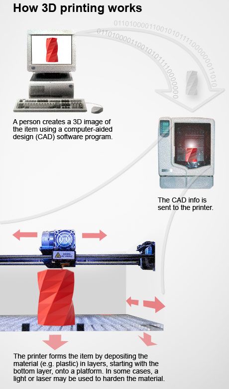
Ways of fastening the workpiece to the table
“Rafts”, “brims”, “skirts” – these terms sound funny, but they just refer to the three main ways of attaching a 3D printed part to a printer table. Let's take a look at each of these methods and their areas of application.
Skirt
The skirt involves creating a few rings around the object at the beginning of the print to make sure the plastic is extruded normally. The skirt is not in contact with the object at all. It surrounds the printable area and helps start the fusing process. When creating a skirt, a large volume of hot thermoplastic polymer passes through the nozzle. This prepares the printer for printing the part itself. This guarantees good adhesion to the table and obtaining smooth surfaces of the object.
Brim
The brim is a wide, flat area connected to the main object as a support base (think of a brim of a hat). It is very similar to a skirt, but connected to the model. In addition to all the advantages of a skirt, the brim keeps the edges of the object being made on the table.
When printing, the outside of an object often cools faster than the middle, causing the edges to curl. Brim prevents this phenomenon by holding the edges.
Raft
A raft is a detachable base, made in the form of a thin mesh platform, located under the entire object (which lies on the raft). To create a raft, the printer first prints a flat plate in two or three layers, and then begins to manufacture the object.
The rafts provide excellent adhesion to the table surface and also provide a strong print base. This is especially useful when making small and oddly shaped parts that do not fit well on the table, as well as thin-walled objects.
After printing is completed, in most cases the raft will separate easily from the part.
If the printer does not have a heated desktop function
Rafts are used if the printer does not have desktop heating.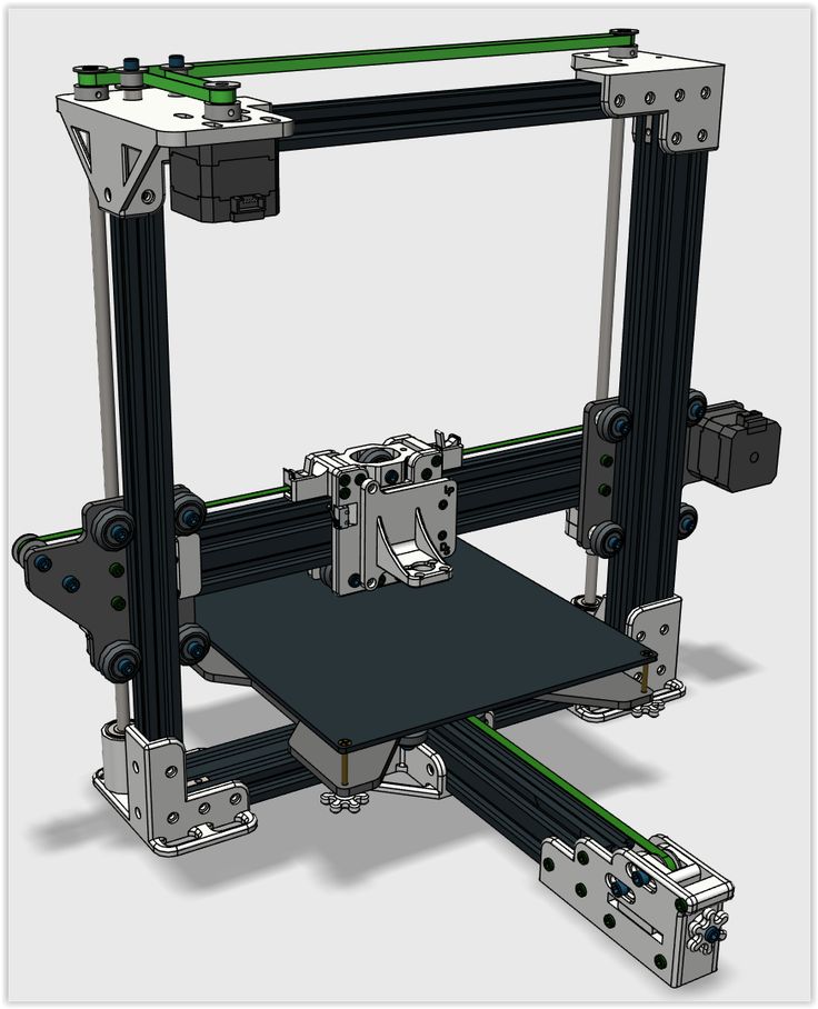 In this case, excessive adhesion becomes a problem.
An alternative method is to apply adhesive paper tape to the printer bed, with the edges down if possible (this also protects the bed). You can also use packing tape, but it is usually more expensive.
If buckling does occur or the object separates from the table, apply a dissolvable glue stick to the adhesive tape. This will enhance adhesion.
Find out the features of a specific 3D printer and take them into account when preparing a model
3D printing is not only a science, but also an art. Effective design for subsequent 3D printing requires an understanding of the technological process, taking into account its features and the purpose of the future object. This will greatly improve print performance.
Using Solid Edge in 3D printing
Not all CAD systems are suitable for 3D printing
The capabilities of the applied system should not limit the designers. Our Solid Edge system is designed with the latest 3D printing technologies in mind. Various 3D printers and 3D printing services are supported.
Take it to the next level with specific techniques for designing 3D printed parts
Generative modeling in Solid Edge opens up new possibilities: the designer selects a specific material, sets the design space, allowable loads, restrictions and target mass of the part, and the system automatically calculates the desired geometry. As a result, 3D printing methods can produce the most complex shapes.
In addition, when building models, the use of the results of three-dimensional scanning is provided. Solid Edge successfully combines the traditional boundary representation of solid models (B-Rep) and the representation of surfaces in the form of a grid of triangles, which avoids time-consuming transformations that are fraught with errors.
If you've already downloaded an STL file for printing, our unique synchronous technology makes it quick and easy to edit your imported models in Solid Edge in preparation for the process.
Printing with your own printer or submitting an order to a 3D printing service provider
Printing in Solid Edge on a local 3D printer is done using the 3D print command. Models can be saved in STL and 3MF formats, or sent directly to Microsoft 3D Builder. If you don't have your own 3D printer or need to try out different materials and surface finishes, Solid Edge allows you to directly submit your models to cloud-based 3D printing services (such as 3YOURMIND). You immediately receive quotes for the production of parts from various materials with its subsequent delivery directly to your door.
3D-CAD from Siemens from this article for 49900r (90% discount), the promotion is valid until March 20, 2020. Read more>>
3D printing replaces CAD/CAM milling
Information / Articles
| 3D printing is a new stage in the development of digital dentistry, which was developed to solve a number of tasks beyond the capabilities of conventional CAD/CAM milling. Compared to milling, printing has several advantages: 1. Save materials. When milling, about 90% of valuable materials are wasted. When printing, you use only the amount of material that is needed to make the structure and a small amount to build auxiliary "support" elements. 2.Precision. When milling, you are limited by the capabilities of the router, the milling strategies used, the diameter of the cutters used, the milling angle, the inability to mill large undercuts, or features that the router cannot physically mill due to the inability to access them. When printing, everything is much simpler, print the form that you need and are not limited in design. 3.Speed. When milling, you simultaneously produce one product, when printing, you can simultaneously produce several tens or hundreds of crowns or other designs. First you need to decide what kind of work you plan to use it for? Unfortunately, there are no universal printers, and here it is important to choose the one that you need and not overpay. The main 3D printing technologies used in dentistry are: 1. photopolymer polymerization (DLP, SLA, PolyJet) The second technology is mainly used for printing structures made of cobalt-chromium alloy (laser sintering), or titanium, or for printing plastic models. The principle of operation is layer-by-layer sintering of the powder using a laser. The first technology is gaining momentum and consists of layer by layer (DLP), dot layer by layer (SLA), or inkjet printing with photopolymer. Among the new developments, continuous polymerization of products should be noted. So not individual layers are polymerized by the method of illumination of each individual layer, but a continuously grown product, projecting a polymerizing video stream into the illumination area. If initially this technology used ordinary plastic with a photoinitiator as a catalyst for the process, now the range of materials used has been significantly expanded and polymers with various fillers are available. Dental biocompatible 3D printing materials are now available that have been certified for class 2a medical devices and can be used for long periods of time in the mouth and approved for contact with blood. For example, biocompatible materials from Nextdent for temporary crowns, for the manufacture of surgical templates, custom trays and removable dentures. There are also many materials for printing diagnostic and orthodontic models. 3D printing in dentistry is becoming more accessible, these technologies are no longer sky-high. There are more and more affordable desktop printers, starting at 3500 euros, that allow you to print not only models, but also a wide range of products used in dentistry. For example, an inexpensive new printer Form 2, from the American company Formlabs. Most dental technicians and dentists can afford it. The Form 2 printer is also convenient because it has a fairly large print area, which means that you can print a sufficiently large number of items at the same time! Some Form 2 printer options
Much more expensive printers are also available on the market. For example, Objet30 Dental Prime, which allows you to print surgical templates, try-in crowns with the possibility of a short stay in the mouth up to 24 hours, orthodontic and control models with an accuracy of up to 100 microns.
There are also many other 3D printers with different characteristics and printing capabilities, open systems and closed ones, in which it is possible to print only their "native" materials, with different working fields and print speeds. |
 These include composite materials for temporary crowns filled with ceramics and materials that were previously processed only by milling, such as zirconia.