Topography 3d print
🗺️ Best STL files 3D printed for topographic maps・Cults
🗺️ Best STL files 3D printed for topographic maps
Download 3D models of topographic maps
Discover our selection of 3D files of beautiful topographic maps perfectly printable in 3D. Whatever your favorite destination, you'll find what you're looking for here, there's everything you need to travel and discover new landscapes, new geographical areas or new countries thanks to 3D printing!
New York, Lower Manhattan
Free
Topographic map of Mont Blanc
Free
Lower Manhattan Cityscape
Free
London, the City
Free
Spherical Lithophane - World Map 12cm remix
Free
Paris, place de l'Etoile with Arc de Triomphe
Free
Dubai, Burj Khalifa
Free
Chicago city
Free
Lamp -_World_Map
Free
Elevation World Map (no multi color printer needed)
Free
Esplanade de la Défense
Free
3D Map - Everest, Himalayas
Free
Mt Shasta Maps
Free
Topographic map of Grand Teton, Wyoming
Free
3D MAP - RIO DE JANEIRO - BRAZIL
Free
South America map puzzle
Free
Gale Crater, Mars
Free
France Map
Free
Europe map puzzle
Free
Mount Hood
Free
Ultra Sierra Nevada Running mountain
Free
Our Dream House in Hong Kong.
Free
Sequoia and King's Canyon Park Maps
Free
Modeling Topography and Erosion with 3D Printing
Free
The Moon Puzzle - v2
€13.16
Trinity Alps Maps
Free
Mount Rainier
Free
Isle of Man - Tourist Trophy Island in relief
Free
Cascade Peaks
Free
Textured Earth (easier to feel)
Free
Vancouver - British Columbia - 3D Map - Topographic
Free
Textured Earth with Braille
Free
USA Terrain
Free
Organ Mountains 3D Model
Free
Desolation Wilderness Maps
Free
Lake and Mountain Topography
Free
Angel Island
Free
Iberian mountain range, mountain chain spain
Free
India Map Shaped Cookie Cutter
Free
Corsican map IGN
€2.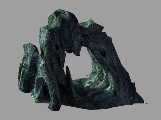 54
54
Mount Rainier
Free
Central America map puzzle (with tutorial)
Free
Formosa (Taiwan) topography models
Free
Antarctica, continent and relief model
Free
Lassen Volcanic National Park Maps
Free
US map keychain (separate states)
Free
Mt. Fuji
Free
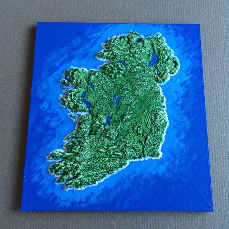
Ireland Map
Free
The Earth Puzzle
Our Dream House in Hong Kong.. a place that every hongkonger spend a lifetime to reach
Dubai, Burj Khalifa
The Moon Puzzle - v2
Here is our selection of the best files for 3D topographic map printers, all these creations come from the STL files repository Cults and are perfectly printable in 3D.
This collection is a collection of free and paid 3D files of beautiful maps created by the designers of our community. No need to take a plane or even a car thanks to these beautiful topographic maps. They will allow you to have a view of a together on a territory or a geographical area, to know its borders and limitations, but especially to know its topology. The different level curves are represented here rather finely which allows to obtain a surprising result of realism and to imagine perfectly the shape of a mountain or a territory.
These 3D printed topographic maps will be an excellent gift for a fan of nature or geography, but they will also be a great souvenir. By printing each summit you climb, you will be able to keep the memory of the ascent, you can even draw on it with a felt-tip pen the route taken to reach the top of the mountain.
The 3D designers who offer their creations on the 3D file download platform Cults have really competed in ingenuity to make all these unbelievable 3D printable topographic maps, if you download them, don't forget to post photos of the result!
Guides Easy ways to 3D print Topographic maps and Landscape models
- What is a topographic map?
- Get a topographic map without a 3D Printer
- What 3D printing technology works best for a 3D Terrain?
- Apps and Sites for Terrain models
- Tips for making your Relief Printable
- How else landscape models can be made
Topographic maps are the maps that represent a relief of the Earth or another cosmic body. In 2D versions, equally elevated areas on topographic maps are connected with a contour. 3D versions of the maps, also called terrain models, allow to recreate the physical relief on a smaller scale. Starting as a tool for military planning, topographic maps are now mostly used for science and architecture.
Another way of capturing the environment is landscape models, which focus on showcasing the scenery of areas. Used in architecture, landscape models include reliefs, vegetation, buildings and even animals based on the desired application. They walk hand in hand with topo maps but commonly add more to them, making a relief filled with life.
Topo maps and landscape models are also used outside of their fields. The three-dimensional versions are fancied as décor and art pieces as they allow to capture the beauty of natural curves.
If you don’t have a 3D printer at home, order a terrain piece from our services. Simply drop your STL into the widget to get instant pricing and delivery estimates.
Relief models are seemingly simple-looking. However, in order to preserve the grace of terrain, it is critical to get the smooth transitions of curves. For this application, our Top-3 printing technologies would be:
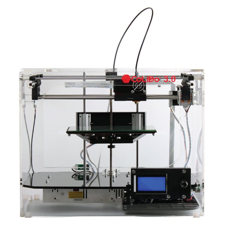
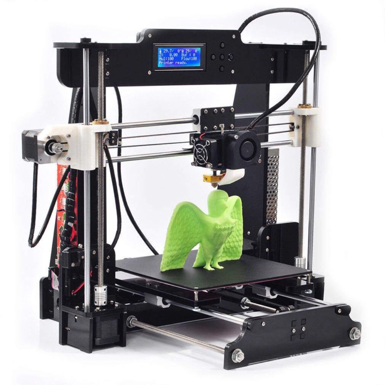
FDM
FDM uses plastic filaments to form objects with a wide range of geometries possible. Desktop plastic modeling may easily deliver poor results on topo maps with too many intricate details. However, if a 3D terrain is properly scaled and optimized with a decent flat base and enough layer thickness, results stand pretty strong. PLA would be the best choice for the material as it provides less trouble when printing and transferring details well.
- - Layer lines on the surface would be inevitable.
- - Details thinner than 0.5 -1 mm would not come out.
- - Monochrome.
- + The most affordable technology for smaller projects.
- + Relatively quick.
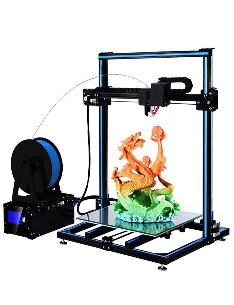
SLS
SLS is a technology that creates parts from powder grains, mostly polyamides. This method suits terrain and landscape models really well, especially bigger ones, which can be printed as single pieces. Fused grains also deliver really beautiful and smooth surfaces with great precision. Going with general-purpose powders like PA12 will be ideal.
- - Hollow models will need to have escape holes.
- - Non-coated SLS objects are yellow over time and absorb moisture.
- - Higher 3D Printing costs.
- + Great accuracy and surface quality.
- + Bigger terrain models are possible to get in one run.
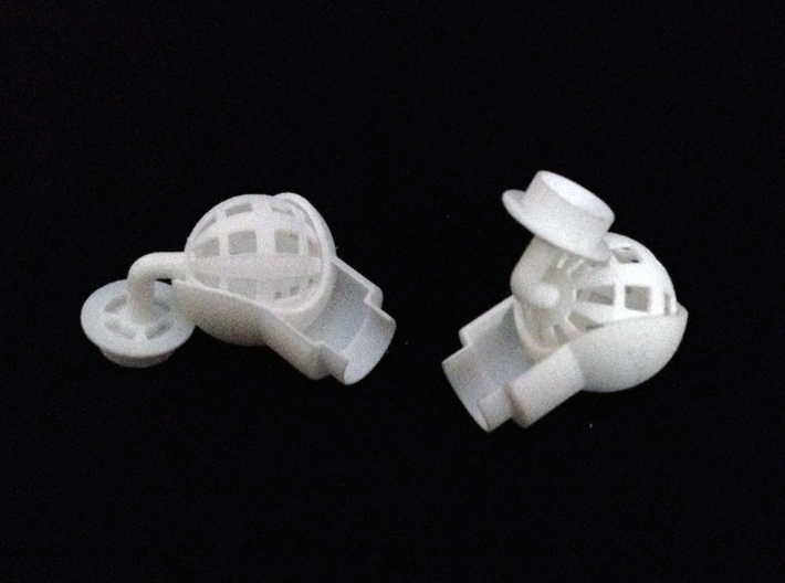
Image credits: ghopper
CJP
While CJP also runs on powder, it uses a binding agent to fuse the grains like sandstone. The resulting models are more fragile but on a good note - colorful. With the CMYK palette possible, CJP can create fully colored landscape models and topo maps. The smallest of the color details may be a bit blurred, so we won’t recommend having tiny text on the terrain. But larger colored areas will turn out nicely.
- - Models are fragile and require a coating to preserve details and colors.
- + Accurate maps in full color are possible.
To get a topo model printed, you will need an STL model, OBJ or another 3D file format. It can be designed manually in suitable software like Blender, Rhino and Solidscape or generated with specially developed apps and sources. Some of the popular and user-friendly are:
Terrain2STL – is a free and open-to-use service for getting models for terrains. Based on Google maps, it can generate a finished file of any surface available through Google’s database.
TouchTerrain is a similar tool, developed by combined forces of Iowa and Kansas Universities It includes more complicated settings, including sun angles.
ReliefMode – generates bas reliefs and lithophanes from 2D images. It allows getting relief of any surface you have a picture of, not limiting you to Earth’s current geology. Though, it will be less accurate due to working from a picture.
Moon2STL – a relative of Terrain2STL, this is the same service but for Moon, which is rich with fascinating craters and hills.
Libraries with ready-to-print models are another, hassle-free way to go. Many designs are available in general-type libraries like Thingiverse, Cults3D, Sketchfab and others.
If you aren’t afraid to take a bit more challenging route, you can explore field-specific databases, which contain Digital Elevation Models. Some of these include OpenTopography and OpenStreetMap. DEMs are a digital representation of terrain received from satellites, lidar data, photos or other equipment. In order to get from DEM to STL, you can use GIS software for converting.
One final option we have for you is the Equator. This online tool allows you to create a markup at any place on the Earth and then export it as a .dwg file. Then, you can convert it to STL in AutoCAD or using an online converter.
The quality of a 3D printed landscape starts from a properly optimized and printable model. So, if possible, after generating your relief, try to make it suitable for your printing method.
For FDM
- Aim to reduce the number of overhangs and angles less than 45 degrees to the base;
- Keep the details over 1.15 mm or at least 0.5 mm;
- Ensure a model's wall thickness of 1.2 mm at least;
- For text, prefer thicker fonts and opt for 1 mm depth/height for it.
For SLS and CJP
- Hollow enclosed parts are not possible, thus, include holes or model parts solid;
- Recommended detail size is bigger than 0.8 mm;
- Suggested wall thickness is around 0.7 mm - 2.0 mm;
- For text details, ensure depth/height about 2 mm.
When plastic doesn’t feel right for you, it is worth exploring other ways to manufacture a terrain model. At Treatstock, we can offer you:
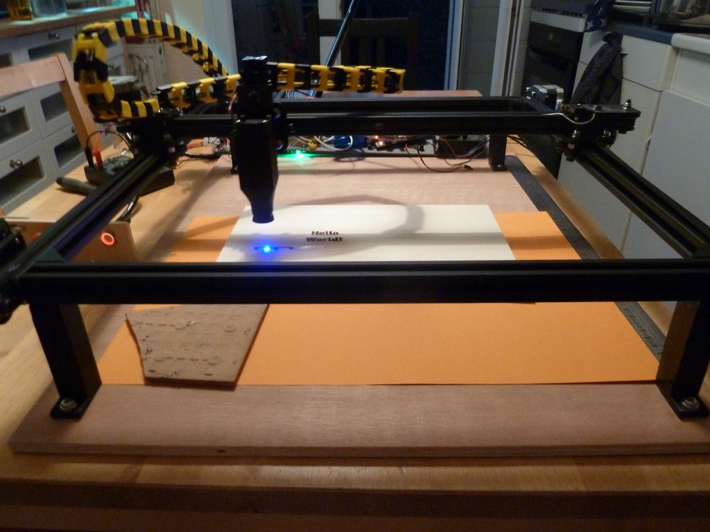
Laser Cutting – a great way to get a flat map or relief contours from woods and acrylics;
CNC milling – for three-dimensional terrains and landscapes from woods, foams and metals.
Architectural 3D Printing Modeling Strategy and Software Usage Guide
At a Glance
3D printing provides tremendous benefits to the conventional architectural workflow. You can print complex designs without the need for skilled craftsmen, and quickly modify these designs without too much difficulty. Stereolithographic (SLA) 3D printing delivers incredibly high surface quality and detail, making it suitable for architectural applications. This paper explores modeling strategies and software workflows that enable architects and designers to easily integrate 3D printing into existing design methodology, create best practices based on internal testing by Formlabs and architecture firms, successfully using Form 2 to create 9 models0005
WHAT YOU WILL LEARN:
Strategies for designing 3D printed architectural models
Tips for improving your workflow Pre-print processing software
- Building information model (Revit, ArchiCAD)
- Surface modeling (Rhino, SketchUp)
Good post-processing techniques
- Compound
- Finishing
Introduction
The 3D printing market today offers affordable options in both price and scale. While professional-grade technology used to be costly, desktop stereolithography 3D printers allow architects, designers, and model makers to offer high-quality, in-house fabricated parts.
Most models cost less than $10 per part.
3D printing opens up opportunities to create complex designs with less effort and fewer materials, but the successful transition from a CAD model to a printable file is based on a basic understanding of design for 3D printing. This document will help you understand how standard modeling constraints relate to preparing a file for 3D printing, as well as approaches and decision making for intelligent modeling - from scale selection to design and assembly for post-processing.
To integrate these strategies into existing workflows, this booklet explores ways to approach modeling strategies tactically by examining three of the most common software ecosystems: allows you to include small details even on the smallest models. This example of a small city model has a scale of 1/32″ = 1’ and is completely printed on a Form 2 3D printer.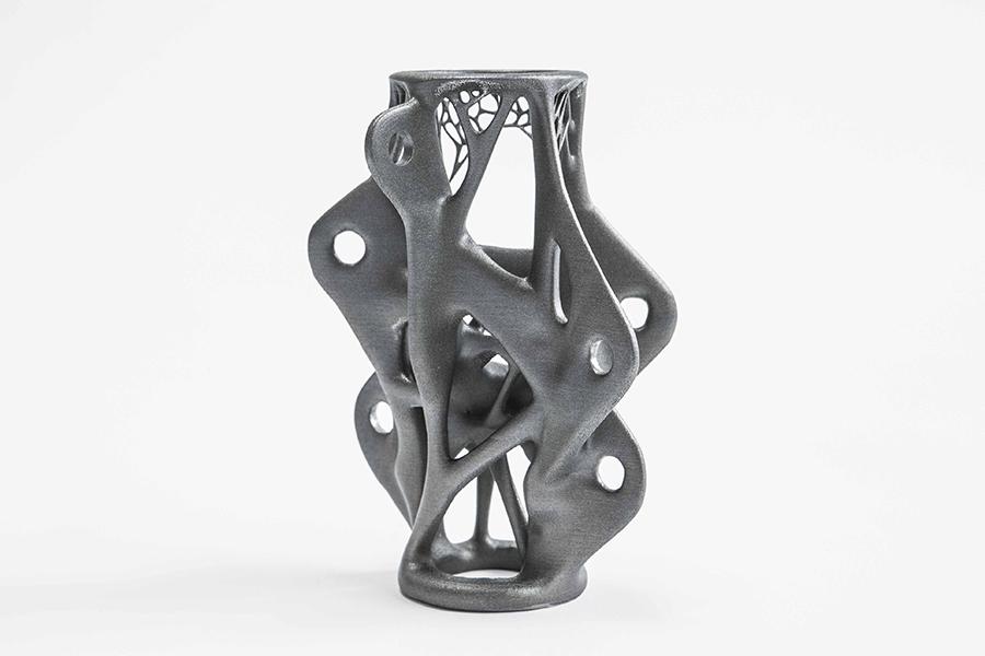 Many small details and parts of this design will take significantly longer if cut and assembled by hand. Model from LaneyLA Inc.
This auditorium section was 3D printed as one piece on a black resin Form 2. Model from DLR Group.
Modeling strategy
Architectural models are usually assembled using various materials and components. 3D printers help combine these components into as few separate parts as possible, but assembly manipulation is still necessary for two reasons:
- Build volume limitations : High build volume printers are either expensive or compromise on surface quality. Form 2 build volume is 57 x 57 x 69 inches (145 x 145 x 175 mm)
- Need to show interior details or materiality : Some models require components to be separated to show more design information.
DESIGN FOR ASSEMBLY
All 3D models require preparation before they can be sent to the 3D printer.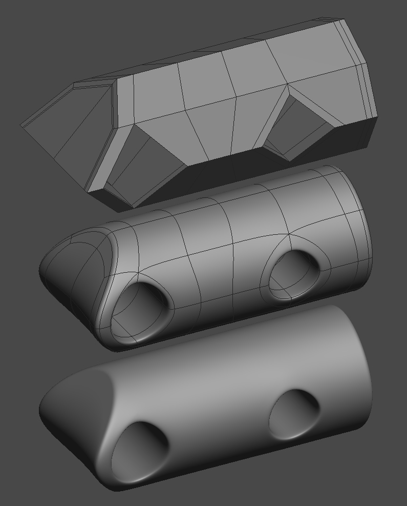 In the case of architectural models for the Form 2, this often involves splitting the model into smaller parts to fit the scope of the Form 2 build. The parts can then be easily joined together by chemical adhesive or mechanical assembly; high precision printing ensures that the parts fit together.
Dimensioning for parts to be separated must take into account the final orientation of the model. Most architectural prints need to be oriented at a 45 degree angle due to floor slabs being considered large horizontal projections. Dividing the model into long, thin parts helps maximize the diagonal length of the build volume while achieving perfect orientation
Strategy overview
There are several strategies for assembling 3D printed models. Your strategy will depend on what you hope to represent with the design, as well as the scale and geometry of the model. Consider the following parameters:
- Need to show internal or external parts
- Easy Split (You want to split the model by the least complex part of the model)
It is necessary to show a certain part of the program: typology, structure, floor layout
| Seam separation | Separation by component |
| Section model | Separation by program |
| Straight cut | Separation by structure |
| Aligners |
Splitting at the seam
STRAIGHT CUT
The easiest way to split the model is with a straight cut.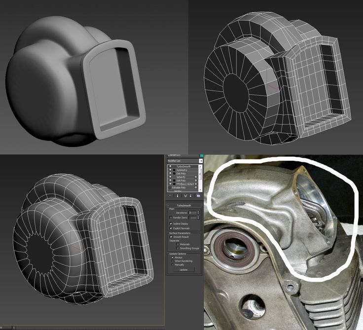 This is a simple command to execute in most CAD software. The bridge model is divided lengthwise using straight cuts into four parts, one of which is shown above. Each support post is inserted into
mating hole that does not require glue. Regardless of which method you choose, if you have a large number of parts (more than 10), it can be helpful to add a unique identifier for each part to help solve the puzzle during assembly.
Pros:
- Least heavy use of CAD
- Greater tolerance for prints that warp or have a higher degree of dimensional change
Cons:
- Assembly requires manually leveling each piece and fixing it in place until the adhesive is fully bonded
Try to print all components in the same orientation so that the layer lines and subsequent dimensional inaccuracies follow the same pattern.
ALIGNMENT TOOLS
Another approach is to add features to the design that will allow the prints to align.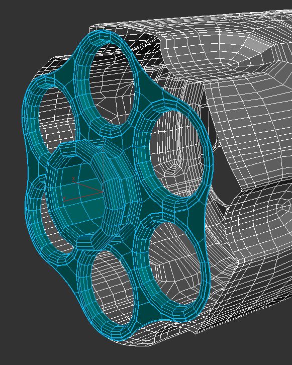 When adding mate fixtures, try to subdivide the model in areas with the least complex geometry. Use the CAD tool of your choice to split your model and add basic alignment fixtures such as slots, pins, grooves, recesses and flanges, or more complex fixtures such as dovetails and cuts that follow existing model curves. In addition, it is important to create a design with ~0.25 mm tolerance between mating parts to prevent additional sanding at the post-printing stage.
Pros:
- Easy alignment Parts that are not accurate
- Easy to assemble (mating parts help create a large surface area for adhesion)
- High precision SLA allows tight fit with high tolerance and can be used without adhesive
Cons:
- Parts that are not true to size will not fit well. High fine details are often less accurate.
SECTION MODEL
The separation of the model with a seam has the additional task of showing the section model for structures with irresistible interior details. Initially, the model can be presented as a whole to the client, and then disassembled to reveal interior details as desired. These LaneyLA examples show how the same model conveys different types of information based on open and closed configurations
This model from LaneyLA was printed on a White Resin Form 2.
Using devices for combining: Methods component
SOFTWARE DIVISION
By splitting a building with software, you can represent the building as a set of parts, providing a clear understanding of all design components without a plan and section drawings. You can print each floor slab separately and then assemble using mates, or just print one component of the entire building separately from the rest. A good example is the model from Stanley Sitetowitz | Natoma Architects Inc (SSNAI), who used the Form 2 to model the residential complex.
Model by Stanley Sitetowitz | Natoma Architects Inc.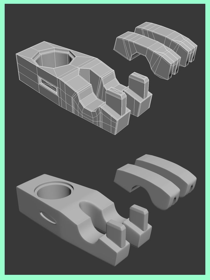
Since each body block followed the same pattern, it makes sense to simply print one detachable block that will allow the customer to understand the typology of the typical device. to print as a single block or separate along the seam.
This method usually works for models that do not have straight lines, such as typical building blocks, but complex structures, such as detailed building sections, bridges, pavilions, or airports.
First, break these models down into components that can be 3D printed with minimal supports. This saves post-processing time (removing supports for delicate models can be tedious) and reduces material costs and print times.
This bridge example demonstrates multiple partitioning methods. First, the model is divided into several parts (Figure a). Although they fit the
Form 2 build platform, they require painstaking removal of supports around more delicate areas such as cables and railings.
To solve this problem, each part is broken down into three sub-components: base plate and railing, vertical tensile cables and solar panels on top (figure b).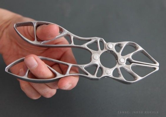 They can be printed with significantly fewer supports, making it easier to finish,
Once completed, the components simply need to be assembled using the alignment functions that were included in the design phase. Smaller parts are also easier to place on a single build platform, with the entire bridge being printed from five 100ml parts.
Model from T.Y. Lin Architects
This site model was created using laser-cut fiberboard. The primary building was 3D printed from clear and white resin. Model by Schwarz Silver Architects
Materials
Materials play an important role in conveying the basic design concept. It is not always necessary to model the exact color and texture of a material, but it can help separate different materials. Dividing a model into its components allows for the display of materiality, as parts can be printed in different materials or individually dyed in different colors.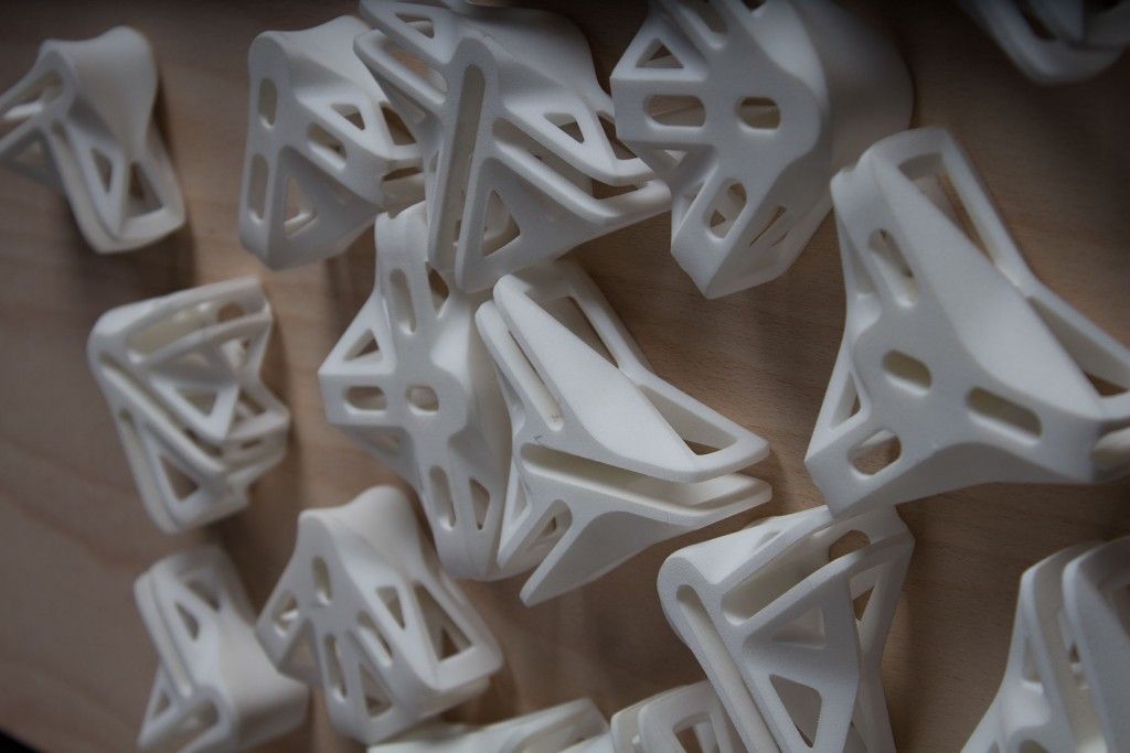
The transparent façade is illuminated from within, simulating the visual conditions of this site at night.
Formlabs Matte Resins
Black, White and Gray out of the printer have a smooth, opaque finish and provide an excellent neutral palette for architectural models. Gray and white resins are also easy to process and can be finished with just a few coats of paint, as discussed further in the finishing section of this document.
Formlabs Clear Resin is excellent for printing features that mimic translucent materials. If your model requires more transparency, you can simply dip the printed part in clear resin and let it dry evenly, as described in this article on making clear resin parts. You can also spray any clear coats on the model to increase the transparency and glossiness of the surface.
3D PRINTING AND TRADITIONAL MATERIALS
This model uses the Form 2 to print very fine details such as the cornice, clock and railing.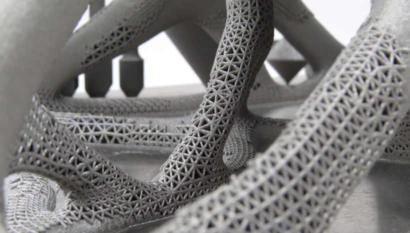 Model by Miles Burke Architectural Models Inc.
Instead of 3D printing an entire building, sometimes it's better to print just the complex components. Complex facades, slings and cornice details are excellent candidates for SLA 3D printing. Flat walls, floor slabs and topography can be laser cut or even hand-drawn
This complex façade is parametrically designed from solar trajectory analysis and would be incredibly difficult to fabricate in any other way at this scale.
Software workflow
Good printing comes from a well-designed 3D model. This section will cover modeling best practices and workflows for printing in some of the most common CAD environments:
Revit, SketchUp and Rhino
CAD software is typically the bottleneck in the transition from drawing to 3D printed model
General workflows
IMZ workflow
IMZ workflow
Model → Revit3Diagnostics → Sketch3Diagnostics 900 PreForm
Although BIM (Building Information Model) software is popular with architecture firms, it is not always used for direct 3D printing models.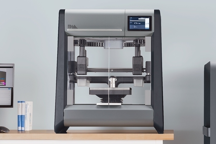 There are some high level steps that you can take
take to create a 3D printed model from these programs. This workflow is widely applied to Autodesk Revit or Graphisoft ArchiCAD software, both of which are IMZ parametric modeling programs.
PREPARE THE FILE
STEP 1: Prepare a stand-alone file
STEP 2: Component Management: remove ducts, double glazing, HVAC units and internal parts that will not be visible in model
STEP 3: Select all components to be sealed (eg doors, windows, walls, slabs). The parametric nature of the model allows you to simultaneously compact the dimensions of several objects.
EXPORT FILE
Select the scale at which you want to export the file. Select export options depending on the needs of your model:
EXPORT AS STL
Exporting the file as a mesh is very difficult to manipulate, so this is only useful if you don't want to edit any geometry after this step. You can then use your software to correct the mesh of your choice, as well as subdivide the mesh along the main Cartesian planes.
EXPORT AS 3D DWG
Export as surfaces allows you to easily manage and edit geometry in Rhino or SketchUp. This step is recommended for those who want to split the model programmatically or by component, or split by a seam that is not on the normal Cartesian plane. You can then export the STL file from Rhino or from SketchUp using the plug-in
EXPORT USING ARCHICAD
Perform a geometry transformation to Morphs and a "consistency check" before exporting the model as STL. When printing in parts, use tool
"Divide" to cut the model for multiple print platforms, if needed. This operation basically creates printable files, but a quick check in mesh repair/analysis software never hurts.
USING STL REVIT EXPORTER
This method automatically removes smaller details such as doorknobs and railings.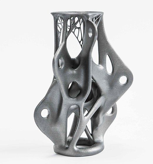 However, it is not reliable and still often requires some post-processing in other CAD environments before being sent to print.
Surface Modeling Workflow
AutoCAD → Rhino/SketchUp → Model Diagnostics → PreForm
This workflow is often an easier approach and starts with 2D drawings solely for the purpose of 3D printing
FILE PREPARATION
STEP 1: Hide unwanted layersSTEP 2: Identify and remove unnecessary elements such as furniture, trees, etc.
EXPORT FILE
STEP 1: Export the simplified drawing from Rhino as DWG
STEP 2: Import into Rhino
STEP 4: Start extruding and trimming until you get the outer shell.
STEP 5: Export as STL STEP 6: Mesh Analysis/Correction STEP 7: Import to PreForm
Note: If the model will be printed in several parts, split it before exporting as STL
THICKNESS WITH RHINO
Instead of parametrically controlling the thickness of components directly in the BIM file, you can also use the BoxEdit component in Rhino.
This allows you to simultaneously scale a number of elements with respect to their center lines. BoxEdit is ideal for models that need to be scaled parallel to three Cartesian axes. Non-uniform scaling is a little trickier.
For non-rectilinear geometries, we suggest converting the part to a mesh and then using the Weaverbird thicken command, which simply offsets any non-standard mesh geometry outward by a given distance. Alternatively, it is possible to "split" complex parts into surfaces and then offset them instead of importing volumes from Revit.
SELECTING SMALL GEOMETRIES WITH RHINO
Another valuable Rhino feature is the SelSmall command, which allows you to select all elements in the Stage that are smaller than a custom bounding box. You can then select those objects and use
BoxEdit for individual scaling or just remove them. This is useful when you are dealing with a file that does not have a well organized layer system.
Although performing a logical connection on all geometries is ideal, often the problem can be solved with simple overlapping geometries. PreForm will interpret them as one closed geometry in most cases, but be sure to check printability with the "slicer" tool in the right pane in PreForm
. CONTINUOUS / LOGICAL JOINT GEOMETRY
Note : PreForm is Formlabs free software that prepares your 3D model for printing in Form 2. Once the part is set up, you can save it as a FORM file for future use in preform.
COMPUTATION WORKFLOW
Although it is a less common workflow, computational design is slowly being introduced into mainstream architectural workflows. Software such as Grasshopper and Dynamo are used to create parametrically generated geometries that are often so complex that they can only be created with 3D printing.
Since geometries are already easy to manipulate, it's usually best to create a separate component that allows you to easily control the basic dimensions of all thin objects. In this case, it's a simple matter of trial and error; running the exported geometries with a print test (PreForm,
MeshMixer) and resizing until you arrive at a printable file.
Model Diagnosis
All workflows described below share a potential "generic diagnosis". This is an optional (but often necessary) step to ensure that the model is fully printable. Free programs such as Autodesk's MeshMixer and Netfabb are tools that allow you to repair, smooth, cavity, and split 3D print files.
MESH FIX
Formlabs PreForm software uses Netfabb's built-in mesh fix, so NetFabb and MeshMixer must be used for custom fixes or to preview problem spots in print. Materialize Magics is a great proprietary tool that covers the entire preprint workflow for a wide range of printer types. The mesh patching software part is most important to the Form 2 print workflow and can save you a decent amount of preparation time. Netfabb has a beautiful built-in model cutter that allows you to effectively split and restore large files along any Cartesian plane.
SPLITTING THE MODEL
You can also split the model in NetFabb, which splits and fixes the split parts into printable volumes. In Rhino, you will need to close open volumes. Be sure to leave a tolerance of ~0.25mm between adjacent parts, this will allow them to be inserted without friction.
For more information on tolerances, see our white paper.
PREFORM SLICER
Architectural models are very detailed and it is often difficult to isolate each print issue. A combination of the above practices and mesh repair software is usually used for almost all problems, but it's always wise to use the PreForm Slicer tool to make sure there are no thin unsupported areas and enclosed volumes (such as rooms with no doors, elevator shafts, and parking spaces) .
“Building and architecture structures are not meant to be 3D printed, they are meant to be built. This creates problems of scale and complex geometry. By combining Netfabb's powerful mesh repair tools with the precision of the Form 2, you can prototype and visualize designs faster and in more detail, benefiting more for your business and speeding up your project's design review process. ”
”
Matt Lemay. Lead Enterprise Solutions Provider, Autodesk Customer Service
Post-Processing
Joining
The modeling strategy section of this booklet covers some ways of splitting and aligning parts together, but glue is always needed to securely join. Architectural parts are bonded in two main ways:
CYANOACRYLATE
Cyanoacrylate (CA or Super Glue) creates a fast, strong enough bond, ideal for small to medium sized parts. CA does not bond dirty surfaces well, so be sure to thoroughly clean the part before applying adhesive to the surface of the model.
POLYMER
For smaller prints, you can use liquid resin as a binder. Dispense a small amount of resin into the tray from a bottle or cartridge, use a dropper or syringe to lift it up, and place it on the surface of the part to be bonded.
Join parts and wipe off any excess resin that may be spilling around the edges. To cure the resin and bond the parts, use a 5 mW laser pen at 405 nm and point it at the bonding area around the parts.
This method creates a chemical bond, just as if the part had been printed on your SLA 3D printer, but only applies to small bonding surfaces because a low power laser pen cannot penetrate the model deep enough to create a strong bond .
FINISHING
Parts printed on Form 2, especially matte standard resins, have a smooth surface as soon as they exit the printer. However, visible areas with supports almost always require sanding. In addition, you can prime and paint parts in any desired color.
GRINDING
Sanding will help you remove the support marks and any remaining inaccuracies from your model. Start by carefully dry sanding the surface of the part using ~150 grit sandpaper to remove large support marks and smooth out the edges of the joint. Once the surface of the part is smooth, wet sand with 320mm sandpaper to remove any remaining layer lines. Move the sandpaper randomly to avoid grain formation.
In most cases these two steps will create a fairly even finish, but you can continue to increase the grit size of the sanding paper by a factor of 2 and wet sand the entire piece until the surface is smooth enough.
Once you have finished sanding your model, wash the model in soapy water to remove any dust or debris and dry thoroughly before proceeding to the last step.
The architectural models are very detailed and it is quite difficult to access certain areas with only sandpaper. You can use different sizes of nail files to get to problem areas of the model.
PRIMER AND PAINTING
Priming is required before parts are painted to ensure the paint adheres to the surface. Priming can also make it easier to find areas that require additional finishing. A quick spray of primer over the model makes the support marks very visible, so you can instantly identify areas that need additional sanding.
General plastic primer gray matt shows details very well. Apply it to surfaces in several thin layers for best results. Continue sanding in critical areas, reapply a light coat of primer and repeat this process until the entire part is smooth. Most spray paints work best in warm, slightly damp conditions with no airflow, but always check the specific paint or data sheet for manufacturer's recommendations.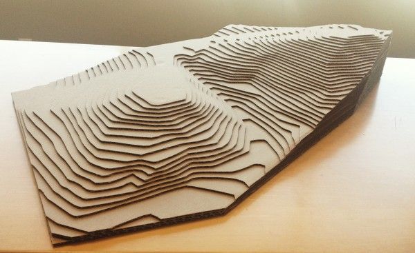
“Models are becoming rarer in a field where photorealistic renderings and virtual reality technology are advancing, but physical models allow architects to test spatial qualities in ways that digital models cannot. If we weren't using a 3D printer, we would be forced to spend more time visualizing designs through renderings and drawings. Being able to get a physical model of a complex design straight from a 3D CAD model gives us several impressive looks in less time.”
Paul Choi
The history of 3D printing from the mid-19th century to today
The early roots of 3D printing can be traced back to the mid-19th century, and its roots can be traced back to at least two technical fields: topography and photosculpture.
Topography
1892 - Joseph E. Blanther patented a method for making topographic maps in layers from wax plates. 1940 - Pereru proposed a similar method for creating a relief map by cutting cardboard sheets along the contour and then stacking these sheets to form a three-dimensional map1964 - In order to improve this approach, Zhang suggested using transparent plates and applying topographic elements on each layer.
1973 - Gaskin describes a 3D geologic educational model
1974 - Mitsubishi Motors' Matsubara proposes the use of photopolymer resin in topography. The method consisted in applying a photopolymer to refractory refractory materials (for example, sand or graphite powder) and forming an integral sheet under the influence of temperature. Further, with the help of a light source (for example, a mercury lamp), certain scanned parts of the layer were solidified. Uncured parts were subsequently dissolved. The thin layers thus formed were stacked together to form a mold.
1976 - DiMatteo recognized that these same laying techniques could be used to produce surfaces that are most difficult to produce using standard machining operations. He cites propellers, air films, 3D cams, and molds as examples.
Photosculpture
1860 - French artist, photographer and sculptor François Willème invented the method of photosculpture. With the help of 24 cameras arranged in a circle and simultaneously photographing the object, he received an exact three-dimensional copy of the object.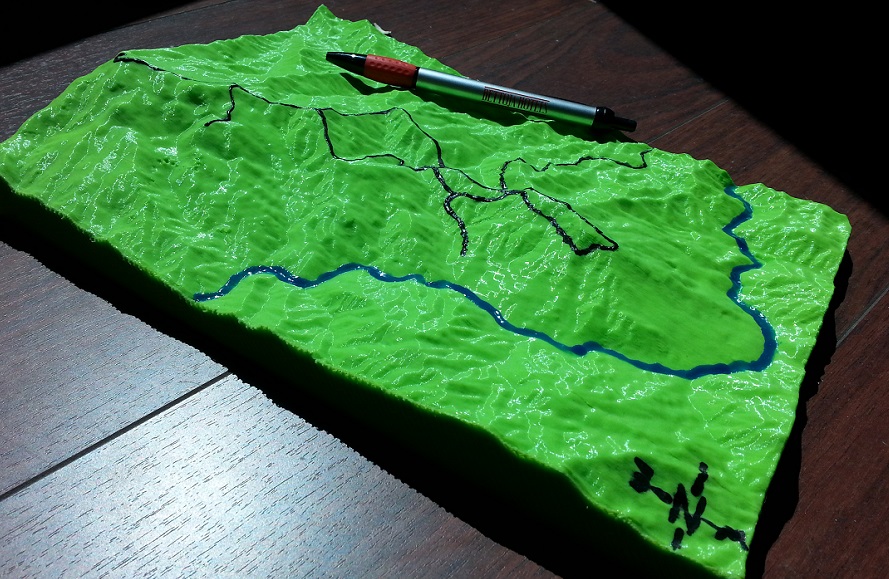 The silhouette of each photo was used to create the prototype.
1904 - In an attempt to facilitate Willem's laborious photosculpting process, Baese described a technique using graduated light on gelatin that expands in proportion to exposure when treated with water.
1935(1944) - In some early work, Morioka developed a hybrid process combining aspects of photosculpture and topography. This method uses structured light (black and white streaks of light) to create the contour lines of an object. Contours can be converted to layers for later trimming and stacking or projecting onto thread stock material.
1951 - Münz proposed a system that has the features of modern stereolithography techniques. He described a system of selective action of a transparent photographic emulsion on a layered image, where each layer is obtained from the cross section of the scanned object.
These layers are created by lowering a piston into a cylinder and adding appropriate amounts of emulsion and fixer. After exposure and fixation, the resulting solid transparent cylinder contains an image of the object. This object can then be manually trimmed to create a 3D object.
Modern 3D printing
1981 - Hideo Kodama of the Nagoya Municipal Industrial Research Institute publishes the first report on the operation of a photopolymer rapid prototyping system.
1984 - 3D Systems founder Charles Hull invents stereolithography (SLA) technology and patents in 1987. The technology allows you to get a 3D model using a laser to engrave an object in a special liquid (photopolymer).
1991 - Stratasys introduces the world's first FDM printer. FDM (Fusion Deposition Modeling) technology uses plastic and an extruder to deposit layers on a print bed.
1992 - 3D Systems manufactures the first SLA 3D printer.
1992 - DTM produces the first SLS 3D printer. SLS (Selective Laser Sintering) is similar to SLA, but uses a powder (and laser) instead of a liquid.
1994 Wax printer invented.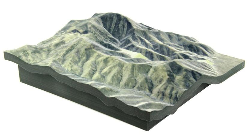
1997 - Aeromet invents laser additive manufacturing.
1999 - Scientists were able to grow organs from a patient's cells and use a 3D printed scaffold to support them.
2000 – Object Geometries produces the first inkjet 3D printer
2000 - Z Corp produces the first multi-color 3D printer.
2001 - Solidimension manufactures the first desktop 3D printer.
2002 – miniature 3D printed kidneys are produced. Scientists intend to produce full-sized, working organs.
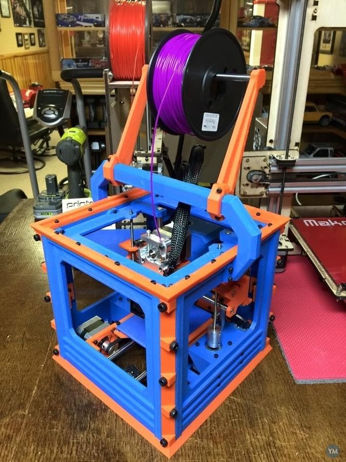
2005 - Dr. Adrian Boyer of the University of Bath founded the RepRap project, which was intended to democratize 3D printing technology.
2008 - RepRap Darwin produces the first 3D printer capable of reproducing many of its own elements.
2008 - Stratasys produces the first biocompatible FDM material.
2008 - The first 3D prosthesis was made.
2008 - Shapeways launches an online store of 3D models.
2008 - Makerbot launches Thingiverse, a site for free sharing of 3D model files
2009 - Makerbot produces an expanded RepRap kit for a wide audience.