Screws for 3d printed parts
How to Choose the Best Fasteners for 3D Printed Parts
Time to read: 6 min
We get a lot of questions about the best methods for fastening different 3D printed components. When prototyping hardware products — like electronics enclosures or robotic assemblies — you often need to design mating structures that are more complex than a single 3D printed component.
Other times, you may need to print components larger than the build envelope of a 3D printer, so you need to consider methods for permanently or semi-permanently assembling printed parts. One of the best ways to assemble 3D parts is with snap-fit components, but another great method is to use screw threads.
There are many ways to implement threads into your 3D printed parts, so in this article we’ll cover the pros and cons of the most common methods. Then we’ll discuss some specific installation steps to help get you started.
Threaded Inserts for 3D Printed Parts
The method we recommend most often is threaded inserts, due to their easy installation and high-quality feel. In addition, threaded inserts for 3D printed parts provide a more secure, robust assembly — they’re even used on aircraft!
Pros
- Fast, easy, and clean
- Can handle repeated installation/removal without degrading the plastic
- Production quality
Cons
- More expensive
- Requires increased wall thickness
Materials and Tools
- Brass Inserts (choose those made for plastic)
- Soldering iron
- Exacto knife
Installation Steps
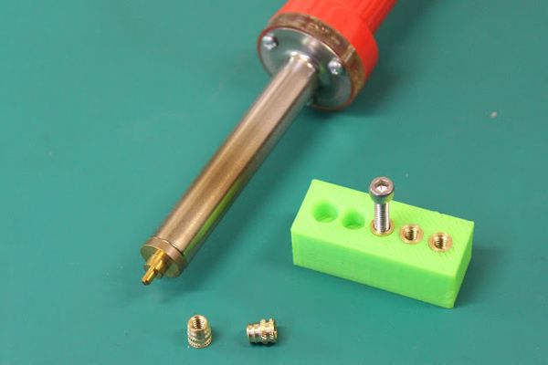
- Place your insert into its associated hole (see insert guidelines for the size of the mating hole)
- Take your heated soldering iron, place it in the middle of the insert and apply a small amount of pressure
- As the insert starts heating up you’ll see it sink into the hole
- Once the insert looks to be flush with the part surface, use your Exacto blade to trim away any extra material
An alternative to threaded inserts for assembling 3D-printed parts is self-tapping plastic screws.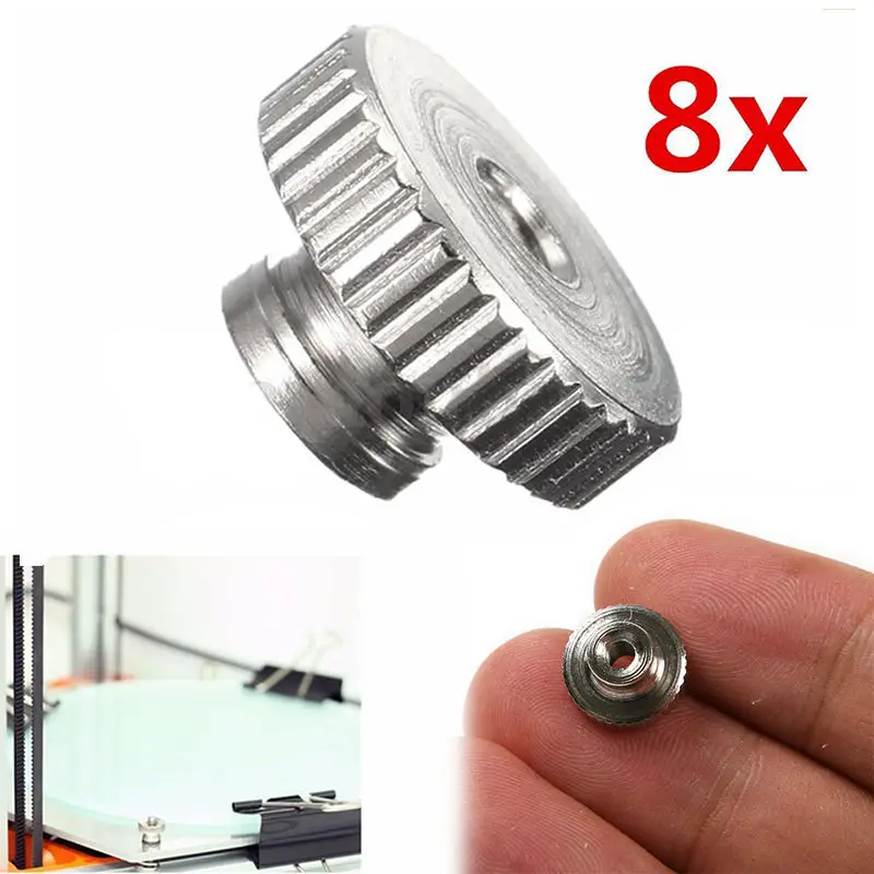 It’s the easiest and cheapest way to go, so if this is your first prototype or you’re using a low-resolution material like PLA, self-tapping screws are a great option.
Pros
- Easy installation
- Minimal design requirements (simple holes)
- Less expensive
Cons
- Brittle material may break (ie. verowhite)
- Limited assembly/disassembly
- Low strength
Materials and Tools
- Self-tapping screws for plastic
- Screwdriver
Installation Steps
1. It’s as easy as a screwdriver and a screw… just twist 😀
Designing Threads into a 3D Model
When designing a part that requires substantial threads, the best method is to design the threads into the 3D model itself. However, note that 3D printing screw threads only works when you are using the correct material and your printer has high enough resolution.
Pros
- Can design custom threads
- Good when inserts aren’t available (ie.
 M50 thread)
 - Works well with brittle materials
Cons
- Threads will wear down over time
- Difficult to model accurately
- Requires high-resolution prints
Materials and Tools
- Your preferred CAD tool for 3D printed model design
Installation Steps
- Ensure your to-be-3D-printed threads are modeled accurately (use equation-driven features in your model — here’s a helpful resource for modeling in inches (UTS), a resource for modeling in millimeters (ISO), and my favorite Engineering Design textbook. You can also follow these quick tips:
a. Shear area of the threaded feature = 2 x the tensile area of the threaded fastener
b. Utilize the following equation for the minimum length of thread engagement needed (for ISO):
Where L=minimum thread engagement length
AT=tensile stress area
D=screw major diameter
P=inverse of number of threads per inch
- Print the component using high-resolution materials (such as Verowhite)
- For internal threads, use a tap to ‘finish’ the threads (see next section).
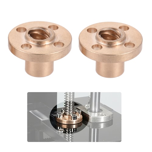 If you don’t have a tap available, try using a machine screw.
 - If you need an externally threaded fastener, use a nut sized to your thread dimension and use this to finish the threads on your component.
- Be sure to tap completely through the component for through-holes — this will ensure excess material is removed from the tapped feature and prepare the part for fastening.
- For blind holes, be sure you’ve tapped deep enough for assembly and make sure to clean any excess material — trying to torque fasteners into components with debris could damage your features.
When using this method to add threads to a 3D printed part, be sure to maintain perpendicular alignment to the threaded feature. It’s worth taking extra care to avoid cross-threading, which could result in permanent damage to the part.
Cutting 3D Printed Part Fastener Threads with a Tap
This is the most traditional method for creating internal threads in a 3D printed part and any other type of manufactured part. In subtractive manufacturing, once a CNC places holes where threads will go, a drill tap is used to create the desired threads in each hole.
When prototyping with 3D prints, you can use the same method with a hand drill tap to create threads in your plastic prototype. I recomment using a hand drill tap (as opposed to a powered drill) to prevent smearing and distortion of the 3D-printed plastic.
Pros
- Better assembly/disassembly than self-threading screws
- Doesn’t involve additional design time
Cons
- Low strength
- Plastic threads wear down over time
- Time intensive
Materials and Tools
- Drill tap
- Screws
Installation Steps
- Tap the threaded feature with a corresponding drill tap to cut usable threads
- Be careful not to damage the component when applying torque
- Install your threaded fasteners in the 3D printed part
Captured Hex Nuts
Another commonly implemented strategy for fastening components together is to create printed-in pockets for capturing hex nuts. This involves recessing a hex-shaped blind volume in the 3D printed part design to allow for simple fastener installation for 3D printed parts.
Pros
- Low-cost solution
- Good holding force
- Easy install
Cons
- Only works on outside surfaces
- Extra material is required to capture the nut
- Design constraints
Materials and Tools
- Hex nut
- Screws
How to use this method
- Measure the size of your fastener — here’s a good resource to help you out.
- Add a bit of tolerance (0.005” – 0.010”) to the hole size to accommodate any dimensional error.
- Before press-fitting the nut into the pocket, apply a bit of glue on the nut to adhere it to the inside pocket surface. Otherwise, as you apply torque to the nut, it may be pulled from the pocket
Pro Tip: For more information on fitment and tolerance, pick up a copy of Machinery’s Handbook
Mechanical Considerations: Fasteners for 3D Printed Parts
Here are three questions to help you consider which fastener method is best for your project:
- Will you need to disassemble and reassemble the components?
- What are your strength requirements or holding forces?
- What are the geometric or spatial constraints inherent in the design of your parts?
Additionally, here are three crucial considerations to keep in mind as you design your fastening features:
- Bending along the axis parallel to printing should be generally avoided becuse printed components are structurally much weaker in this direction.
- Be mindful of the allowable stress and strain of your materials when adding assembly features.
- Double-check your CAD model before adding fastening features. For example, if you’re adding a hex nut, check the height of the hex nut you’re using and If you’re using a threaded insert, check the pitch of the insert you’re installing.
With these ideas in mind, you should have no trouble creating larger, more complex assemblies with your 3D prints, and for additional questions ,send us a note at [email protected].
Sourcing SimplifiedIf you’re tasked with sourcing and supplying 3D printed parts, Fictiv has you covered as your operating system for custom manufacturing. We make procurement of prototype and production parts faster, easier, and more efficient. In other words, Fictiv lets engineers, like you, engineer.
With our design and manufacturing expertise, and innovative platform that provides instant DFM feedback, complete production visibility, and quick turnaround times, manufacturing your parts is easier than ever!
Get Instant Quote
Thank you for subscribing!
How do you assemble 3D-printed parts? Practical tips on threads & screws for 3D printing
What are the ideal ways to assemble 3D-printed components? This article compares different methods for designing threads for 3D printing and provides step-by-step instructions on how to install screws and other fasteners.
Threaded fasteners, such as screws and inserts, are a popular method for securing 3D-printed parts together. Threaded fasteners allow quick assembly and disassembly, granted the threading has been designed and printed properly, and provide robust connectivity so parts don’t come apart easily.
This article covers the optimal threaded fastening techniques to apply when dealing with 3D-printed parts and examines the methodology behind implementing each of them.
To learn more about the different types of threads, especially if you're also interested in CNC machining custom parts, read our extensive guide to threads .
What are threaded fasteners for 3D printing?
As a rule of thumb the minimum wall thickness around a thread should match the diameter of the fastener (e.g. an M5 fastener requires a minimum of 5mm wall thickness around the threaded hole). If the wall thickness is too low, parts can bulge and distort due to the added stress and in some cases (particularly with FDM) delamination or fracturing can occur.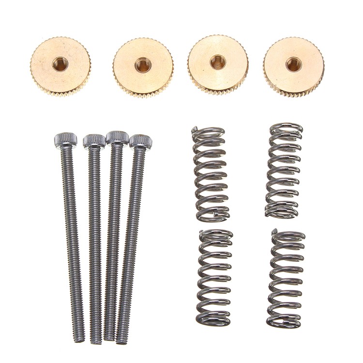
The table below introduces the threaded fastening methods that are best suited to 3D printing.
| Process | Description |
|---|---|
| Inserts | Popular method used regularly that gives a strong metal-on-metal connection but requires additional components and installation |
| __Embedded nut __ | Fast method for securing components. Accurate design and print are needed |
| Self-tapping screws | One-off method for securing parts that is not optimal for repeated disassembly |
| __Cutting threads __ | Provides design freedom however correct tapping procedure is important |
| __Printing threads __ | Not suited for small threads (less than M5) and requires high printer detail/resolution to print accurately |
Note: Drilling the pilot or alignment hole to the desired diameter post-printing, before implementing any of the fastening methods discussed in this article, will typically give a more accurate diameter compared to a 3D-printed hole.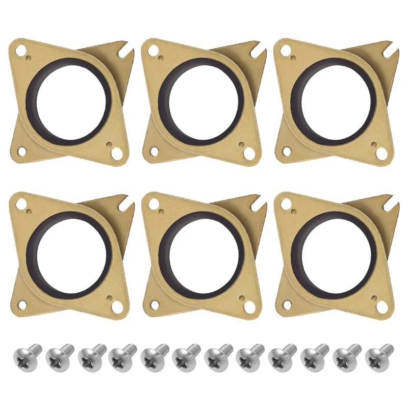
What are inserts for 3D print assemblies?
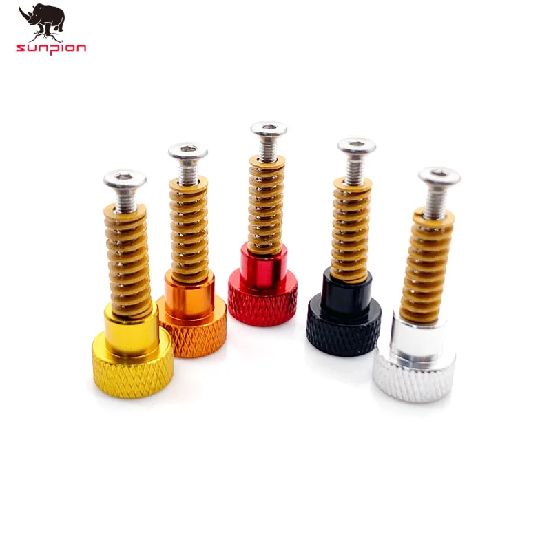
The two types of inserts that are best suited for 3D printing are heat-set inserts and tap-in inserts. Inserts provide strong metal-on-metal contact and are very easy to install. An accurate pilot hole is required, so drilling is recommended before installation.
Methodology for heat-set inserts
-
Align the insert with the pre-printed or drilled hole (for hole sizes refer to the insert manufacturer's recommendations)
-
Insert a soldering iron into the insert, heating it and the surrounding material up (avoid overheating and melting the surrounding material)
-
Slowly apply pressure, pushing the insert down into the hole to the desired depth.
Methodology for tap-in inserts
-
Align the insert with the pre-printed or drilled hole (for hole sizes refer to the insert manufacturer's recommendations)
-
Using a hammer gently tap the insert down into the hole to the desired depth.
What is an embedded nut in 3D printing?
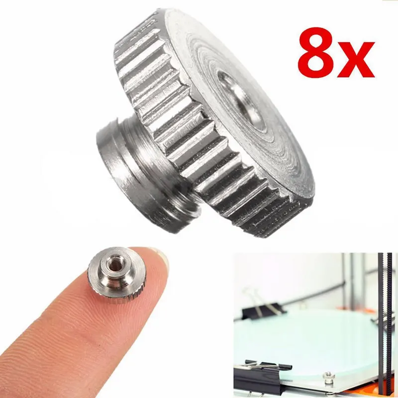
Another method of securing 3D printed components together is to embed a nut into the component via a nut-shaped cavity (often referred to as a nut boss). This method does not require any material removal. Often determining the optimal nut boss dimensions requires several iterations. Printing small test parts to determine the ideal dimensions can save on time and material costs.
Methodology for embedded nuts
-
Measure your nut. If you do not have access to the nut a quick internet search will reveal standard overall dimensions for both metric and imperial nuts.
-
Include the desired nut profile in your CAD model . An iterative process may be required to find the best nut clearance based on printer calibration. As a starting point a 0.2 mm offset around the nut (0.1 mm on each side) should give a loose fit. This also may need to be increased for nuts greater than M12.

-
Select the appropriate cut-out depth (typically just below flush).
-
Including a drop of superglue on the back side of the nut will help secure it in place.
What are self-tapping screws?
Self-tapping screws cut a thread into a pre-drilled hole as they are screwed down. This offers a quick assembly method but is not suited for applications where parts will regularly be assembled/disassembled. Special self-tapping screws for plastic can be used that limit the radial stress on 3D printed holes lowering the likelihood of bulging, delamination or fracturing occurring.
Methodology for self-tapping screws
-
3D print or drill a hole in the desired screw location. For optimal pilot hole size consult the self-tapping screw provider. A pilot hole size that provides 75% to 80% thread engagement is a good starting point if this information is difficult to come by.
-
Assemble components to be secured ensuring to correctly align all holes where the self-tapping screws will be used.
-
Slowly screw the self-tapping screw down into the hole, ensuring it remains perpendicular to the hole during fastening.
What is thread cutting (or cutting a thread) for 3D printing?
Thread cutting (more commonly known as tapping) involves using a tap wrench to cut a thread in a pre-printed or drilled hole. Threads are regularly cut in 3D printed plastics.
Methodology
-
3D print or drill a hole in the required location of the thread. For pilot hole (tap drill) sizes that correspond to each thread size refer here
-
Using the correct size tap wrench and ensuring it remains perpendicular to the hole, slowly cut the thread regularly reversing or “backing off” to remove excess material to avoid binding.
-
Avoid forcing the tap wrench as this can lead to fractures or splitting of the 3D printed material.
-
Continue tapping to the desired depth.
Insert your desired threaded fastener before assembly to ensure a clean fit.
Cutting a thread with a tap wrench3D printing threads for assembly
The process of 3D printing threads eliminates the need for any extra steps post printing and allows parts to quickly be assembled together. Limitations on printer accuracy and resolution will govern the success of a printed thread. Threads smaller than M5 printed via FDM should be avoided with one of the other threaded fastener methods discussed in this article implemented instead.
After printing the threaded fastener should be screwed and removed from the hole several times to clean the printed thread before final assembly.
Practical advice for threads, screws & more assembly methods for 3D printing
-
For a more accurate fastener pilot hole consider drilling the hole after printing rather than printing it in the part.
-
The minimum wall thickness around a thread should match the diameter of the fastener (e.g. an M5 fastener requires a minimum of 5mm wall thickness around the threaded hole).
-
Heat-up or tap-in inserts and embedded nuts are the most popular methods for securing 3D printed components due to their simple installation, connection strength (metal-on-metal) and ease of repeated assembly and disassembly.
Curious about the cost of prototyping with 3D printing?
Our online 3D printing services Upload a CAD file for a free, instant quote
Ready to transform your CAD file into a custom part? Upload your designs for a free, instant quote.
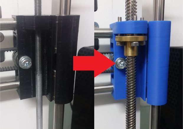
Get an instant quoteSecond "z" screw for Ender-3
When converting Ender-3 from bowden to direct, in my opinion, it is required to install a second "z" screw.
Whoever is not interested in reasoning, then go directly to part 2.
Part 1 - "Theoretical".
To begin with, I looked at ready-made solutions. I suggest you consider them.
1. Kit with stepper motor. For example like this.
2. Without stepper motor, with timing belt. For example like this.
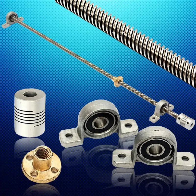
3. With printed parts, without stepper motor, with timing belt. A trapezoidal threaded screw (hereinafter referred to as a T-screw) is fixed in one flanged or support (on feet) bearing. For example like this.
4. Using printed parts, no stepper motor with timing belt. The T-screw is fixed between two bearings. For example like this.
All these solutions IMHO have some problems.
Solution 1 uses two stepper motors without a timing belt, and this solution is problematic. The owners of Anet are well aware of this. Installing a second motor and timing belt at the same time on the Ender-3 is, in my opinion, pointless.
Solutions 2, 3 and 4 fix the T-screw at three points, which means that there will be a wobble with a high degree of probability.
Solutions 1 and 2 cost more than I would like. In addition, it is obvious that you can do it cheaper and certainly not worse.
Solutions 2 and 3 have cantilever pulleys, which means that normal belt tension will not be possible. When the belt is tensioned, the T-screw will flex.
Solution 4 is the best in terms of securing the timing belt pulleys, but as mentioned above, wobble is possible. Plus, printing and post-processing parts for this upgrade is complicated (cleaning out the supports of the bearing recesses is not the most pleasant task).
Further, it is necessary to formulate the requirements for technical solutions for the second screw of the "z" axis:
1. Timing pulleys must be fixed between two bearings. The bearings must be located in close proximity to the pulleys (as in example 4).
2. Possibility of adjusting the bearing assembly in the horizontal plane (as in example 3). We eliminate possible problems with wobling.
3. Minimum cost.
4. Try to avoid fixing the T-screw in three points.
As a result of a simple simulation, the following came out:
Left (when viewed from the front) T-screw mount:
Printed mount in green. Red printed spacer washers, 2 mm thick. The chamfer on the washer is directed towards the bearing.
Right T-screw and engine mount:
I made three holes for the engine mount, but could only tighten two screws. Do not remove the hole now)) All other design features are the same as on the left T-screw.
Belt tensioner:
I made a slot for spools with an inner diameter of 5 mm, but I still had F688zz bearings, so I made an adapter sleeve and used them.
Second portal carriage "x":
Made two degrees of freedom in the T-nut bracket (can be moved in two planes).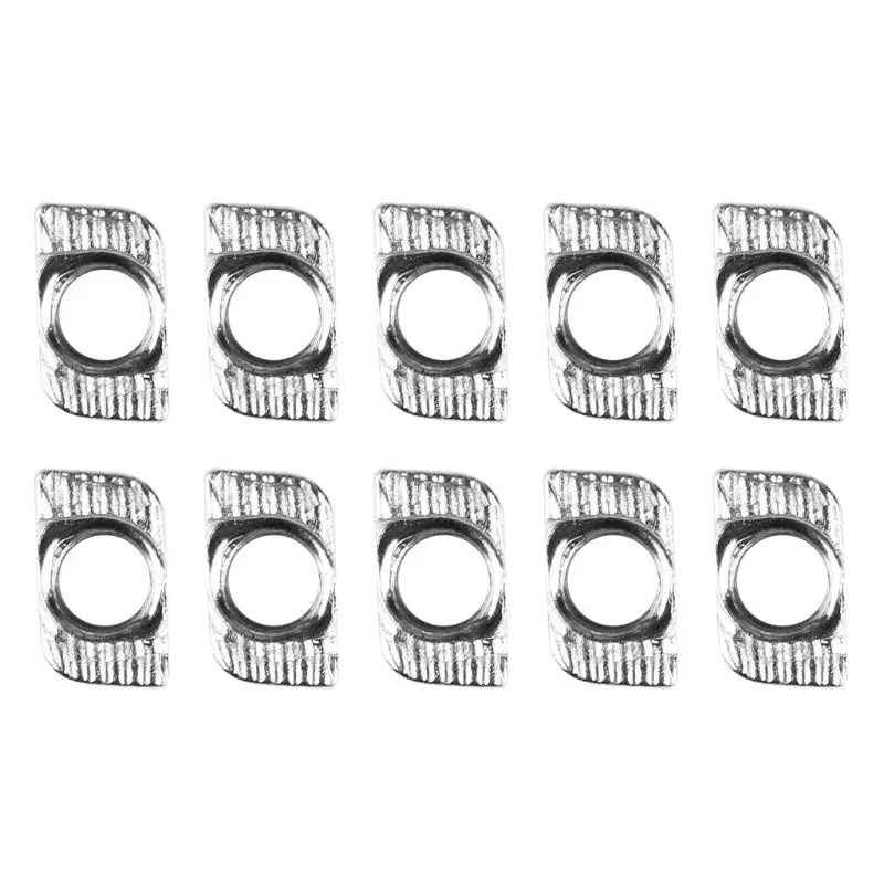 The carriage has recesses for M3 nuts on the reverse side, designed to attach the T-nut bracket.
Power supply mount:
To mount the power supply, drill d4.5-5 mm holes in the plastic part (there is already a thread on the power supply.). I made a tool holder on top of the power supply, but for my needs it goes slightly into the print area. On thingiverse I saw solutions for moving the block to other places.
To summarize part 1:
1. Timing belt pulleys are fixed between two bearings.
2. It is possible to adjust the fastenings of the T-screws in the horizontal plane in a small range of 1-2 mm.
3. Minimum set of accessories.
4. The T-screws are fixed at two points (on the T-screw attachment and on the T-nut). This item is valid if you move the engine up.
Part 2 – Practical.
The following components are required for assembly (I will give links to aliexpress, where I purchased it myself, not advertising, not a referral):
1.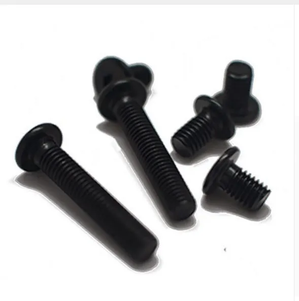 T-screw d8 mm Pitch 2mm Lead 8mm, length 350 mm.
2. Ring toothed belt 2GT-6 mm, length 610 mm.
3. Timing pulley 2GT - 2 pcs. 20 teeth bore 8 (20 teeth, hole 8 mm).
4. Flange bearing F688zz (8x16x5) - 10 pcs. Instead of 10 pieces, you can buy 5 pieces and a parasitic pulley with an inner diameter of 5 mm, it will come out cheaper.
5. Fasteners. Didn't count. I just took it out of the box. If necessary, then write - I will count.
6. Wires. Approximately 4m 24AWG (I used 0.25mm2 PVC insulated audio wires).
7. Ph3.0 terminals. I have not used it myself yet, but extended the existing wire. Ordered here. When they bring me to redo this disgrace. You may need 6 pin connectors - such.
Item 6, 7 if moving the engine up.
The cost of the main set (positions 1-4) is $10-15.
Printed almost everything in black ABS, but PETG can also be used. I printed out a tool holder from PETG. When printing T-screw fasteners, it is desirable to place supports in the bearing holes.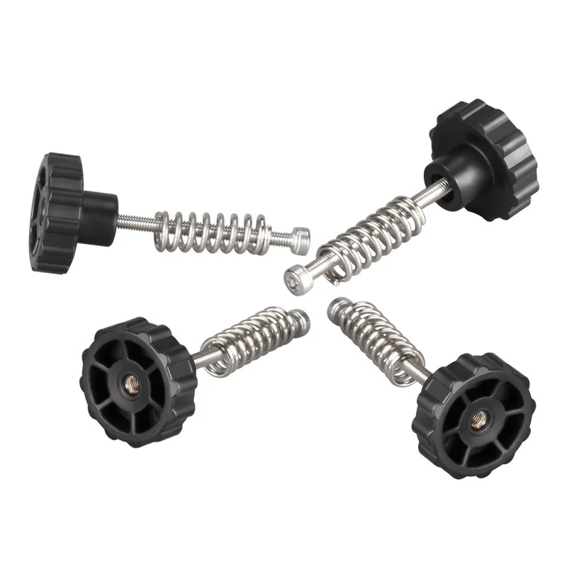 Elsewhere, at your discretion. Printed with a layer of 0.2.
This is what happened:
When assembling the left and right screw mounts, it is necessary to correct the height of the spacer washers on sandpaper or stone. Chamfered washers. Be sure to wash on the larger side (no chamfer). Side with a chamfer for a stop in bearings. All parts should go in with little effort. Initially, the size of all parts is larger than necessary by 0.4 mm.
I pre-assembled and adjusted without a belt. I used a clerical scalpel as the axis of rotation. An M8 bolt can be used.
When the left and right mounts are assembled, you can proceed to install all this on the printer.
Before installation, turn off the printer and remove the power supply. Install the second portal carriage "x" (using standard nuts and screws). Install T-nut and second T-screw.
Separately, the following must be noted. If you don't want to move the stepper motor to the top, then you can leave it on the bottom (in the design place), but this will require careful adjustment of the left T-screw mount.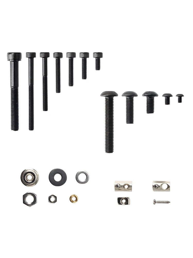 In this case, the lead screw will be fixed at three points.
Before tightening the bolts on the left and right T-screws, the x-axis gantry must be raised as far as it will go. After that, tighten the mounting bolts. Care must be taken to ensure that the T-screws are vertical in both planes. Pay attention to the distance from the screw to the plane of the printer frame - they should be the same at the entire height.
Next, put the clutch and the motor in place. We haven't hooked up the engine yet.
Align the portal to the horizon. I did this with a caliper relative to the top beam.
Tighten the screws on the pulleys.
Install the belt tensioner.
Check if the stepper motor is disabled. No matter what happens - loosen the clutch on the stepper motor. Raise the x-axis gantry to the very top, then press down on the center of the gantry so that it goes down (you may need to lubricate the T-screws). When the portal descends, we look at the beating of the screws in two planes.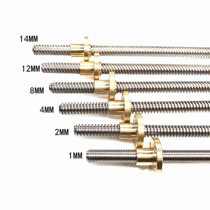 By adjusting the position of the fasteners and T-nuts, we achieve a minimum runout. There will be runout, since all the screws are a little uneven, including the regular one from Ender-3. Written in this paragraph IMHO. I have not checked what will happen if you do not remove the beating of the screw, but I will not risk it.
For laying wires to the engine, I suggest using these profile plugs. And lay the wires in one or two channels of the vertical profile. When cutting, it is better to increase the width of the plug by 1-2% - so it will snap into the groove more tightly. I increased it by 2%.
If you move the stepper motor up, you must invert the rotation of the "z" axis. How to do this, read on the portal. For example here.
The right bracket has holes for a cable tie. You can attach a wire to them.
Below is a photo of printing with gray ABS plastic. In my opinion: gray plastic is the best way to see printing problems. As you can see, there are some shoals of printing (I'm dealing with this now), but wobble is not among them.
Another ABS part. I also printed with the second screw on the "z" axis in the same way, but the stepper motor was on the bottom. There is no wobbling.
Tool holder made of PETG.
Posted the details on the portal. Each part needs to be printed one copy, except for the remote washer (Ring.STL) - they need 6 pieces (4 for installation, 2 in case you “miss”).
P.S. If something does not fit, then use a needle file.
3D printing - threads and screws
First things first: what is the difference between a screw and a thread?
A screw is a fastener used to form a connection that can later be dismantled, while the thread is the main fastener of the screw. In this case, the thread is not only used for screws; they are also present on pipes, in linear drives, worm gears and many other devices.
The common feature of all threads is the way they are formed. Each thread is a continuous spiral groove of a certain cross section, made on the outer or inner side of the cylindrical surface.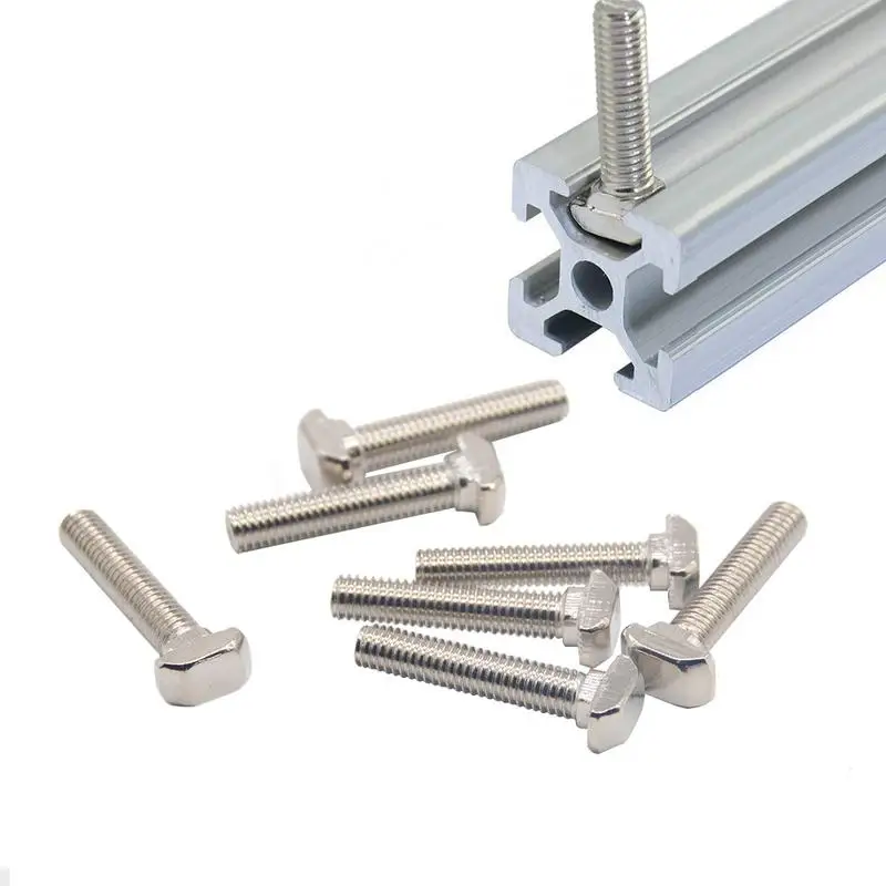
In most cases, the cross section or shape is triangular or trapezoidal. Triangular thread forms are primarily used for fasteners (screws), while trapezoidal thread forms, varieties of square threads, are used for power transmission and linear drives on lead screws. To keep things simple, this article only covers triangular shaped threads, but everything applies to both types.
A further level of categorization distinguishes metric threads from inch threads. The former are mainly used in Europe and Asia, while the latter are used in America and the UK. To the untrained eye, they look the same, but the difference exists in the shape of the triangle and the pitch of the spiral curve.
In this article, we will cover the basics of designing and 3D printing screws and threads.
Basic Terms
There are a few terms and concepts that you should be familiar with before you start designing a thread.
External or internal thread : External or external thread exits the cylindrical surface.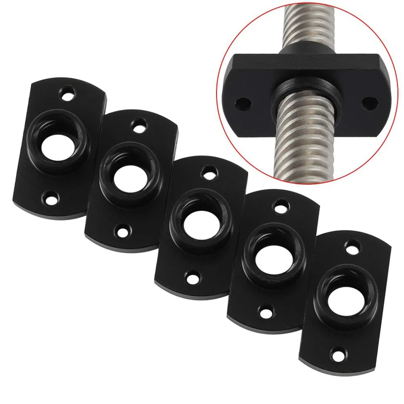 The female thread is cut on the inner cylindrical surface. For example, bolts have external threads, while nuts have internal threads.
Thread axis : a line passing through the center of the cylinder on which the thread is formed.
Base : the bottom of the groove that runs around the body of the thread.
Comb : The highest point of the thread profile.
Large diameter : The diameter of a cylinder enclosing the top of an external thread or the base of an internal thread. This cylinder is concentric with the axis of the thread.
Minor Diameter : The diameter of a cylinder enclosing the root of a thread on an external thread or the crest of an internal thread. This cylinder is concentric to the thread axis and large diameter. The smaller diameter is also known as the drill diameter when handling internal threads.
Pitch : distance between equivalent points on adjacent threads.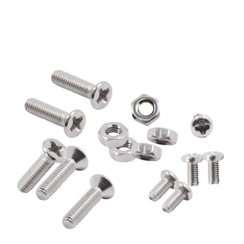 For example, the distance between two adjacent crests of a triangular thread.
Metric thread: The "M" designation of a metric thread indicates the nominal outside diameter of the thread in millimeters. For example, an M5 thread has a nominal outer diameter of 5 mm. For external threads, the nominal outside diameter is equivalent to the major diameter. For internal threads, the nominal outside diameter can be determined by measuring the minor diameter and referring to the metric thread table.
Inch threads: Inch threads are designated using a number of standards, including the Unified Thread Standard (UTS), which basically refers to standard thread sizes as numbers (eg #4). The two most important measurements in UTS are the major or minor diameter of external or internal threads, respectively, and threads per inch (TPI).
Thread Modeling
Let's look at the process of designing external and internal threads using Fusion 360, which provides a simplified threading functionality.
Other CAD programs have tools of varying degrees of similarity. It is important to understand the basics presented in the previous section. With this knowledge, you will be able to use any available modeling tool for 3D modeling.
Let's start with the outer thread of the bolt.
External thread
- Draw a circle with a diameter equal to the largest diameter of the desired thread.
- Create a cylinder by extruding a circle to the desired thread length.
- Go to "Create" and select the "Thread" option.
- Select the newly created cylinder. Make sure "Modeled" is checked. Set the thread type and other thread options. Click OK.
That's it. You have an external thread! To make a good bolt out of it, you need to attach it to the head to your liking.
Now let's create a nut with an internal thread.
Internal thread
- Create a hexagon. For the purposes of this tutorial, just make sure it's larger than the carving you want to create.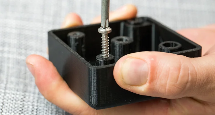
- Press it out to the desired height.
- Make a hole in the center by selecting the "Hole" option from the "Create" menu. The hole diameter must match the largest thread diameter.
- Select the inner surface of the newly created hole, go to "Create" and select the "Thread" option.
- Don't forget to check the "Modeled" option. Set the thread size and other parameters. Click OK.
That's it. Your first carvings are ready for 3D printing!
Tips for 3D Printing Threaded Parts
This may seem like a simple task at first glance, but printing threads is not always easy, especially if you need small diameters.
Assume you are using a 0.4 mm nozzle and a 0.2 mm layer height. With this setting, the smallest pitch you can achieve during 3D printing is likely to be around 0.5mm (give or take 0.1mm). This pitch is suitable for M3 threads and you should have no problem trying to print an internal thread on a relatively large part. This is because your threads will have enough time to cool while the nozzle is in a different location.
Things get interesting if you need an external thread, for example on a screw or bolt. In this case, the nozzle has nowhere else to go, which means that you will probably need additional cooling. Check your 3D printer before you decide to print a lot of thin external threads.
One of the most practical options before starting thread printing is the M10 3D Printed Thread Test. Thanks to this special 3D model, you will be able to check exactly what your 3D printer is capable of.
Settings when 3D printing parts with threads
Below are some general guidelines for setting up your 3D printer when printing threads.
- Make sure your 3D printer is properly calibrated. Extruder calibration is also important.
- Always try to print threads vertically. For best results, the thread axes should be perpendicular to your 3D printer table.
- Print without the calipers, or at least make sure they don't go inside the threads. Otherwise, removing them and maintaining functionality can be a real problem, especially with internal threads.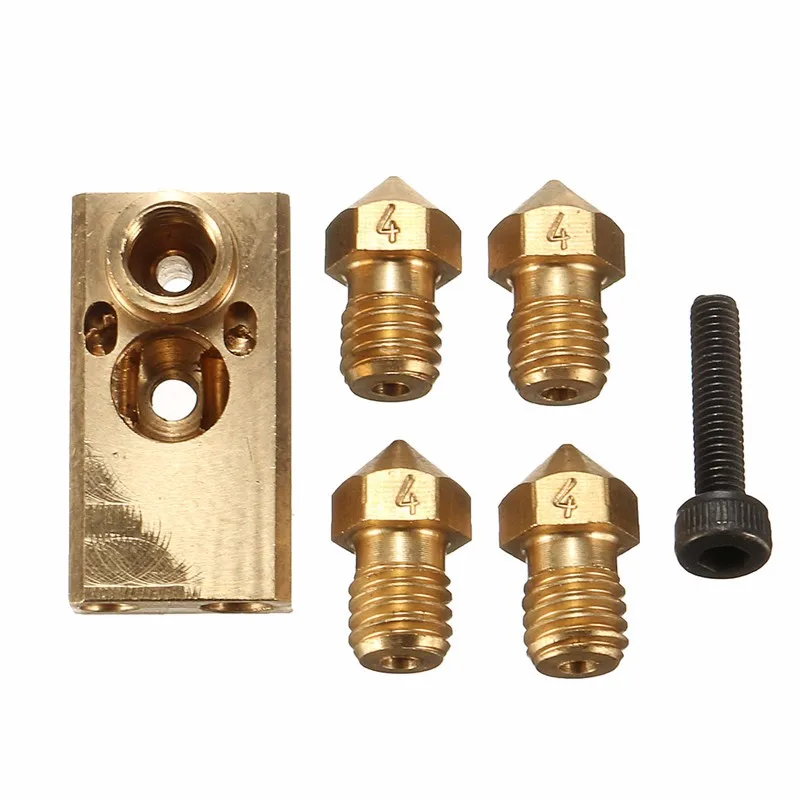
- If possible, use at least 4 vertical layers or vertical walls at least 2 mm thick. This will ensure the strength of the thread.
- Try to set the filling density to at least 25%.
- Layer height is an important parameter when 3D printing threads. For smooth operation, the layers should be as thin as possible. As a guideline, threads larger than M12 or 1/2" can be successfully printed at 0.2mm, while smaller threads should be printed at thinner layers.
Resume
Even if your first test fails, don't despair! Here are some final tips for 3D printing threads:
- Even if you manage to print beautiful external threads smaller than M6 (6mm in diameter), think twice before using it for heavy duty use. Due to the small diameter and the nature of 3D printing, this thread size is best suited for visual models only. If it must be a functional piece, consider a different design.
- Internal threads less than 4 mm in diameter have a small pitch, which makes 3D printing difficult.