Raspberry pi zero 3d printer
PrusaPrint (Rpi Zero and Octoprint)
Relevant for
:
MK3MK3SMK3S+
Last updated
10 months ago
This article is also available in following languages:
Raspberry Pi Zero W has no 5GHz Wi-Fi (only 2.4GHz), and a somewhat weak processor. It does not support using a large amount of Octoprint-plugins or streaming of video and is not officially recommended by the OctoPrint project. Use more powerful models like the 3B+ or the latest RPI 4 to take full advantage of Octoprint. However, they do need to be connected by USB, plus they need a separate PSU, which results in a less clean setup.
In this article, we will outline the preparations and configurations necessary to outfit your MK3S with Octoprint using a Raspberry Pi Zero. Here we will go through how to solder the correct GPIO pins and connecting the Raspberry Pi to the printer.
PRUSAPRINT (PRUSA'S CUSTOM OCTOPRINT IMAGE) IS NOW OUTDATED NO AND LONGER BEING MAINTAINED! If you wish to use Octoprint, we recommend following the guide to creating your own Octoprint image. We will launch PrusaLink and PrusaConnect, Prusa's own solution, in the near future.
You can run Octoprint from most versions of the Raspberry Pi (Zero, 2, 3, 3B, etc.), but this is covered in a different article. We have chosen the Raspberry Pi Zero W for this tutorial, as it integrates neatly with the MK3s Einsy RAMBo with no need for an external power supply.
This guide is not covering any other fruit alternatives, like Banana Pi, Orange Pi, etc.
Distinguish between models Pi Zero W and Pi Zero. The letter "W" stands for Wireless. Buying a cheaper Pi Zero without WiFi will not work with this guide!
Parts and preparations
To complete this guide you need the following components:
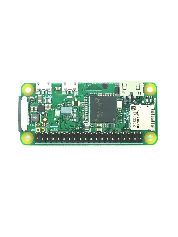
- Raspberry Pi Zero W
- 2x20-pin Strip Dual Male Header, with 18 mm pins.
- Micro SD card of at least 8GB (16 GB is recommended).
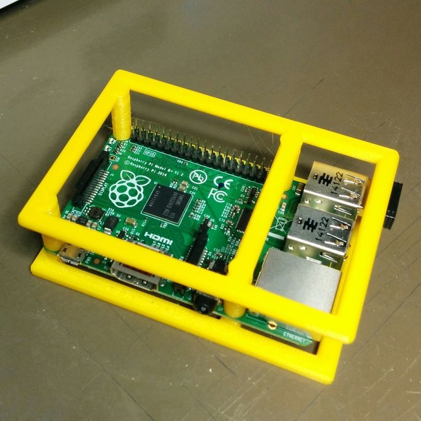
- Printed RPi Zero Frame.
To create a connection between RPi Zero W and EINSY board you need a GPIO header which you solder to the RPi board. You need a break-away 2x20-pin Strip Dual Male Header, the version with 18 mm pins. These types of headers come in different versions, but the crucial part is that they are 18 mm long.
2x20-pin Strip Dual Male Header
Now that you have your Pi and the pins, they need to be installed to the Einsy Rambo. To ensure the correct position of pins and optimal distance, our developers created a printed part, the RPi Zero Frame, which is placed between RPi Zero and EINSY board. This is also used as a template when soldering the pins, ensuring they go where they should.
RPi Zero Frame
RPi Zero Frame can be downloaded here. Recommended settings for print are profile 0.2 SPEED and material PETG or ABS.
The RPi Zero Frame is not fully compatible with the RPi Zero 2 layout. Be careful if using it or seek out a remix.
Soldering the GPIO pins
Certain parts of this guide require the usage of soldering and cutting tools. Please read carefully the instructions for such devices/tools and use personal protective equipment. Prusa Research does not assume responsibility, and expressly disclaim liability for loss, injuries, or damage.
Prepare a piece of the GPIO-header, as in the illustration above, by simply breaking off the length you need and pulling out the pins you do not need with some pliers (right picture).
We are connecting this header to the UART pins (5V, GND, TXD, RXD) for serial communication, and to GPIO22 as mechanical support.
Sandwich the printed frame, the RPi Zero, and the GPIO pins together like is shown in the right picture below, Make sure the tips of the GPIO pins stick out about 1 mm, from the correct holes. You are now ready to solder the pins.
When soldering, you need the solder to "flow", creating a proper bond between the pins and the pads on the RPi Zero. If you end up with balls and blobs you need to reflow it for a proper bond. The solder needs to be clinging to the pins and the pads. You want "cones" as in the pictures above and below. Most solder will also turn shiny if done correctly. If you have no experience soldering we recommend looking up some videos on the basics.
Installation of SD card
The RPi Zero W hardware is now ready to be installed to the Rambo case, but for the lack of access once installed, you first need to prepare the SD-card which runs its operating system.
- Build and configure your own image from scratch
PRUSAPRINT (PRUSA'S CUSTOM OCTOPRINT IMAGE) IS NOW OUTDATED NO AND LONGER BEING MAINTAINED! If you wish to use Octoprint, we recommend following the guide to creating your own Octoprint image. We will launch PrusaLink and PrusaConnect, Prusa's own solution, in the near future.
Connecting the RPi Zero to your printer
- Make sure the printer is turned off and carefully cut all the indicated plastic parts and remove the cut-out part. During the cutting process, MAKE SURE YOU DON'T CUT the Einsy board!!!
On the MK3 (non S) there might not be this prepared area to cut. You can still cut it out, but this is a bit scary and you won't have the protective cover. We recommend printing the latest version of the Rambo-case.
- Slot the RPi Zero, with its frame, into the connector holes indicated below (green square). Then fit the cover to protect the RPi Zero W (purple arrows).
- Make sure the RPi Zero is properly installed by inspecting the connector on the other side of the Einsy Rambo (green arrows).
 Notice that the position of the support pin is in the corner (purple arrow).
Checking if the RPi works
Go to the printer's LCD menu -> Settings -> RPi port, and make sure it is set to ON. Return to the printer's home screen. Now, wait for a few minutes. The RPi Zero is not a superfast computer and it needs time to boot.
Then open the browser and try opening a website: octopi.local. If octopi.local doesn't work, please use the following steps: Check your router for a new IP address, using an app like Fing, or wait until the address is displayed on the printer's display.
As soon as you have the IP, open a web browser on your PC, type it in, and hit Enter. If the Octoprint webpage loads, you can continue.
Troubleshooting
OctoPrint provided by Prusa Research is tested and is confirmed to be booting correctly. If you can't access the web interface, check the following:
- Is the RPi port enabled on your printer?
- Did you enter the correct Wi-Fi name (SSID) and password?
- Is the RPi Zero W correctly plugged in the EINSY RAMBo board?
- Are you connected to the same Wi-Fi network?
3D Printing | Raspberry Pi Zero Stand
3D Printing
Save Subscribe
Please sign in to subscribe to this guide.
You will be redirected back to this guide once you sign in, and can then subscribe to this guide.
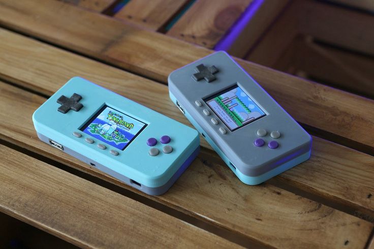
Pi Zero Projects
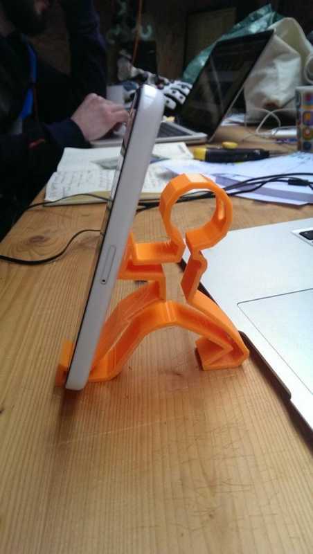
Display your Pi Zero on your desk with this simple yet useful stand. 3D prints in one piece and doesn't require any supports. It features mounting holes for securing a Pi Zero. A hole in the stand allows for wires to pass through for USB power and peripherals.
Pi Bonnets, Hats and Add-Ons
There's heaps and heaps of accessories for the Raspberry Pi Zero, from touchscreen and displays to HATs, and Bonnets, there's something for your project! Check out all the goodness Adafruit shop has to offer! Use the link below or just use the search bar.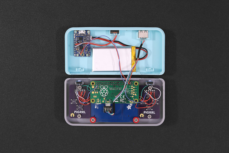
Adafruit Pi Bonnets
Parts & Hardware
A Pi Zero W, microSD card and microUSB cable is about all you need for this project. You can grab one of the Pi Zero Kits to get you going. You'll also need additional hardware to secure the Pi Zero W. Pi uses M3 mounting holes but you can use M2.5, we have a handy M2.5 nylon standoff kit.
- 4x M2.5/M3 x 5mm female/male standoffs
- 4x M2.5/M3 x 5mm button head screws
- 4x M2.5/M3 hex nuts
Raspberry Pi Zero W Starter Pack - Includes Pi Zero W
Remember those cereal commercials that would always say, "part of a complete breakfast"? Well the Pi Zero's a lot like that bowl of cereal - while it's...
Raspberry Pi Zero WH (Zero W with Headers)
NOTE: Due to stock limitations we may only be able to offer refunds or store credit for Pis that are defective, damaged or lost in transit.If you...
Black Nylon Machine Screw and Stand-off Set – M2.5 Thread
Totaling 380 pieces, this M2. 5 Screw Set is a must-have for your workstation. You'll have enough screws, nuts, and hex standoffs to fuel your maker...
- Your browser does not support the video tag.
3D Model
The stand is a one piece design that does not require any support material. It's parametrically driven so the viewing angle, thickness and size can be easily modified by changing a parameter. Check out my Layer by Layer tutorial on how I set that up using Autodesk Fusion 360.
Slice Settings
Use these settings as reference. Values listed were used in Ultimaker's CURA 3.X slicing software.
- 0.2mm Layer Height / 0.4mm nozzle
- 0.38mm Line Width (inner & outer widths)
- 40mm/s printing speed
- 20% infill
- Supports: No
Download CAD Files
Design Source Files
The enclosure assembly was designed in Fusion 360. This can be downloaded in different formats like STEP, SAT and more. Electronic components like the board, displays, connectors and more can be downloaded from our Fusion 360 CAD parts github repo.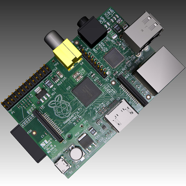
Download Adafruit CAD Parts
Fusion 360 Share Link
Assembly
This guide was first published on Feb 13, 2019. It was last updated on Feb 13, 2019.
This page (3D Printing) was last updated on Oct 31, 2022.
Text editor powered by tinymce.
how to install OctoPi on Raspberry Pi
3DPrintStory 3D printing process Installing OctoPrint: How to Install OctoPi on Raspberry Pi
What is OctoPrint? To answer this question, here is a list of OctoPrint features:
- Wirelessly upload G-code files from a computer to a 3D printer
- Manually control the 3D printer (moving the X, Y and Z axes, and force plastic extrusion)
- Controlling the print temperature and changing print settings
- Set up the webcam viewable in a browser
- Slicing the model with CuraEngine
- Customizing the work with many plug-ins (you can even write them yourself!)
Many 3D printers upload files either via an SD slot or via a USB port.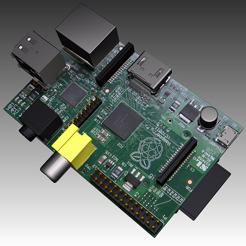 This means that you need to, for example, insert an SD card into your computer, load a G-code onto it, and insert it into the 3D printer every time you want to print something. And for a printer without an SD card slot, the computer must be connected throughout the entire 3D print.
With OctoPrint, there are no such inconveniences. It works with almost all 3D printers to make managing your 3D printer much easier with its wireless capabilities. It's not necessary, but thousands of hobbyists use OctoPrint to make their lives easier.
Various plug-ins available that provide additional features, including custom time lapse creation, external monitoring/control via smartphone, and even Telegram integration for remote monitoring.
What do you need?
To get started with OctoPrint, you will need the following:
- Raspberry Pi : Although the official recommendation for OctoPrint is Raspberry Pi 3 Model B, you can use the latest Raspberry Pi 4, although it is recommended to add a cooling fan because this model can get very hot.
 Raspberry Pi versions 1 and 2 may also work, however they will require a USB Wi-Fi adapter as they do not have this feature built in. Unfortunately, the cheaper Raspberry Pi Zero isn't quite up to the task.
 - RPi Power Adapter : This item is usually overlooked, but it is actually very important to ensure that enough power is supplied to the board. According to the OctoPrint website, the Raspberry Pi 3 is powered by a 5.1V micro-USB power supply, and the 2.5A power supply should provide enough power to run OctoPrint. Undervoltage can cause performance issues and should be avoided.
- Micro or full size SD card : Purchase whatever fits your Pi, along with an SD adapter to connect it to your computer. If you don't plan on queuing a lot of 3D models with OctoPrint, an 8 GB card is sufficient. For users planning to print in large volumes, it is worth looking at 16 or 32 GB cards.
- USB cable : used to connect the Raspberry Pi to a 3D printer.
 Pay attention to which output on your 3D printer is USB type A, type B, mini or micro. On the Pi, it's USB-A.
Of course, you will also need a 3D printer that works with OctoPrint.
Loading the OctoPi image
The easiest way to get OctoPrint up and running is to boot the Raspberry Pi with the OctoPi image. To do this, you will need an SD card flashing tool. And for that, we recommend Etcher, which is free for Windows and MacOS.
The steps are:
- Download the latest version of OctoPi (currently 0.18 or newer).
- Unzip the downloaded image by double clicking on it. You must have an image file with an ".img" extension.
- Insert an SD card into the computer (or connect with an adapter). Please note that when using Etcher, there is no need to pre-format the SD card. In fact, OctoPrint specifically recommends "do not format the SD from within your operating system, even if prompted to do so".
- Open Etcher, select your SD card, select the OctoPi image and click "Flash".
 Once this is done, you can begin!
WiFi setup
Now that the OctoPi image is installed on your SD card, you will need to enter your WiFi network name and password so that your Pi can actually connect to the internet.
- If Etcher removed your SD card when it stopped flashing, be sure to reinsert it into your computer.
- Open your SD card (the directory is usually called "boot"). It should be located where external drives usually appear.
- There's a whole bunch of files here, but don't be alarmed. We need "octopi-wpa-supplicant.txt".
- For Windows users, open the file in Notepad. For MacOS users, open the file in TextEdit. (Under "Preferences" select "Plain Text Format" and uncheck "Smart Quotes"). You can also open the file in other text editors such as Atom or VSCode.
Here's how to change the Wi-Fi details and country code:
- Most Wi-Fi networks are WPA / WPA 2 protected. In the first network block, remove the first "#" from the four lines as shown in the image above.
- Enter the name of the Wi-Fi network in the "ssid" line and the password in the "psk" line, keeping the quotation marks in place.
- If you want OctoPrint to connect to multiple networks (eg home Wi-Fi and telephone hotspot), simply copy and paste the network block (four lines) and fill in the details.
- Enter your country code below. If you are in the UK, this has already been done for you. Otherwise, you will need to enter "#" in front of the word "UK" and remove the "#" in front of your country name.
- Make sure the blocks match the image above, especially the "#" character matches.
- Save the file and remove the SD card from the computer.
If you run into any problems, be sure to check out the official OctoPrint WiFi Setup FAQ, which includes troubleshooting tips for many potential issues.
Communication Security
Each Raspberry Pi comes with a default SSH username and password. Therefore, it is highly recommended to change the password to prevent other users from connecting to your OctoPrint and controlling your 3D printer.
- First boot up the Pi and connect to it via SSH.
- Insert an SD card into the Pi slot. If a Wi-Fi adapter is required, make sure it is plugged into the Pi's USB port.
- Turn on the Pi by connecting the power cable to the micro USB port. Connect the other end to the power adapter.
- Open CMD (Windows) or Terminal (macOS) and run ssh [email protected] (or replace octopi.local with the IP address assigned by your Raspberry Pi router).
- If it returns "Are you sure you want to continue connecting (yes/no)?" type "yes" and press Enter.
- Enter the Pi's default password: raspberry. Press Enter.
At this point, you should have gotten into the Pi system. To change the default password, do the following:
- Run sudo raspi-config. It should ask for the default password again.
- The first option should be "Change User Password". Press Enter.
- Enter the new password twice.
All. Your OctoPrint instance is now protected. Use this new password every time you want to access the Pi via SSH.
Connecting the Pi to a 3D printer
It's time to put everything together. In this step, we will connect the Raspberry Pi to your 3D printer:
Power off the Pi by unplugging the power cable from the micro USB.
Connect the cable to the 3D printer and the USB end to the Pi.
Turn on the Pi and your 3D printer.
OctoPrint interface setup
Once the Pi has booted up, you will be able to access OctoPrint via LAN.
- Enter "http://octopi.local" (or the IP address assigned by your RPi router) in any browser. Make sure your computer is connected to the same network as the Pi.
- You should see the OctoPrint interface and setup wizard pop up. Follow the instructions and don't forget to enter your OctoPrint username and password. Please note that this is not the same as the username and password you have set for your Raspberry Pi.
- Connect to the 3D printer by opening the connection panel on the left.
 After setting the parameters to "AUTO", click "Connect". If that doesn't work, try manually setting the serial port and baud rate until it does.
Congratulations! You have successfully configured OctoPrint. To start your first 3D print with OctoPrint, click the "Upload" button in the bottom left corner and select your G-code file. Once imported, all files will be listed in the Files panel. Click the small printer icon to start printing.
Not so difficult, right? Now you can freely explore all OctoPrint features and plugins!
How to install and configure OctoPi on Raspberry Pi. How to connect to a 3D printer.
Detailed OctoPrint quick start guide. Installing OctoPi, connecting to a 3d printer
What is OctoPrint (OctoPi)? OctoPi is a Raspbian distribution installed on the Raspberry Pi single board computer that contains OctoPrint , a 3D printer remote control tool.
Here is a small list of OctoPrint features:
- X, Y and Z rotations.

- Webcam connection.
- Loading the G-code on a 3D printer.
- Temperature control.
- Set print options.
Downloading and writing the OctoPi
image The latest version of the OctoPi image can be downloaded here - octoprint.org/download/. The image is compatible with Raspberry Pi A, B, A+, B+, 2B, 3A+, 3B, 3B+, 4B 1/2/4/8GB, 400, Zero, Zero W and Zero 2.
We will use special software to write the image - Raspberry Pi Imager . You can download the program from the following link - raspberrypi.com/software/. After downloading, install it on your computer.
A program with a very simple interface. Only 3 buttons are available here: " CHOOSE OS " - select the operating system, " CHOOSE STORAGE " - select removable media, " WRITE " - write the image. And there is also a settings button that will appear after selecting the image.
First, select removable media , click on the button " CHOOSE STORAGE " and in the window " Storage " select the USB flash drive (in my case it is a MicroSD memory card).
By clicking on the " CHOOSE OS " button in the " Operating System " window, we will see a menu where you can select a ready-made image or your own. In this menu, you can also choose to format the memory card. For good, it's better to erase the data from the memory card before writing the image - click on the item " Erase (Format card as FAT32) ".
In the warning window " Warning " we agree by pressing the button " YES " that all information from the flash drive will be erased.
And wait while the Raspberry Pi Imager application erases files from the drive.
Upon successful formatting, we will see the window " Write Successful ", which will say that the removable USB device has been erased and the memory card can be removed from the card reader. We press " CONTINUE ", but do not remove the memory card.
Now press again the button " CHOOSE OS " and select the item " Use custom (select a custom . img from your computer) " to select the previously downloaded OctoPi image.
In the explorer " Select image " select the OS image and press the button " Open ".
On the right in the main menu window of the Raspberry Pi Imager program, a settings button will appear in the form of a gear, click on this button.
An additional OS settings window “ Advanced options ” will appear, in which we specify the computer name “ Set hostname ” to identify the device on the network. We provide access via SSH « Enable SSH " if required.
If you have selected the “ Enable SSH ” setting, select the “ Set username and password ” setting and set the username and password for access via SSH (it is better not to change the “pi” login). We also set the “ Configure wireless LAN ” setting, in which we specify the name and password from the Wi-Fi network in order to connect to OctoPrint through the web face in the browser. To save the settings, click on the " SAVE " button.
The settings have been saved, now it's time to write the image to the memory card, to do this, press the button " WRITE ".
After finishing the write process, we will get the window " Write Successful ".
Now we connect the Raspberry Pi single board computer to the 3D printer via a USB cable.
OctoPrint settings
So, in order to access the web-face, you need to enter the computer name in the address bar of the browser, which we set in the Raspberry Pi Imager settings before recording the image. In my case the name is:
http://rapberrypi.local
Alternatively, you can enter the IP address in the address bar instead of the PC name. To find out the IP address, you can use a network scanner, or open a command prompt (CMD) and enter the command:
ping raspberrypi.local
After pinging by computer name, I get the IP “192.168.1.40”, in your case it may differ.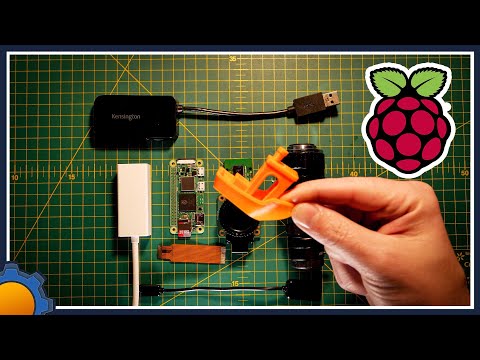
Open the browser and enter the name or IP, press the key " Enter ". At the first start, we will get into the OctoPrint installation wizard in the section " Start ". To continue, press the button " Next ".
Section " Restore Backup ", if you do not need to restore the backup, click " Next ".
Create an account in the " Access Control " section. In the “ Username ” field, enter the username to access OctoPrint, in the “ Password ” and “ Confirm Password ” fields, enter and confirm the password, then press the “ Create Account ” button, and after “ Next ".
In the “ Online Connectivity Check ” section, a connection check is configured, the default interval is 15 minutes, you can not configure anything here, go ahead, click “ Next ”.
The " Anonymous Usage Tracking " section allows or disables the collection of OctoPrint performance data. Regardless of the choice, press " Next ".