3D printer retraction problems
How to Avoid 3D Printing Issues Using Retraction Settings
3D Insider is ad supported and earns money from clicks, commissions from sales, and other ways.
Retraction is one of the built-in functions of FDM printers that can help address several 3D printing issues, particularly those related to over-extrusion. The great thing about retraction is that it can be tweaked very easily via your slicer.
The basic parameters of retraction are distance, speed, and minimum travel distance. Other 3D printers may offer more advanced settings such as enabling “combing mode.” The optimal retraction settings can vary based on the filament you are using or the model you are printing.
Fine-tuning your retraction settings may take a bit of trial and error, but there are good starting points we can recommend so that you’ll get there faster.
How does retraction work?
Retraction is a mechanism that allows the extruder to “pull back” a short segment of the filament. This happens via a reverse rotation of the extruder gears. By pulling back some of the filament, pressure on the hot end nozzle is relieved. This makes it less likely for molten filament to ooze out of the nozzle.
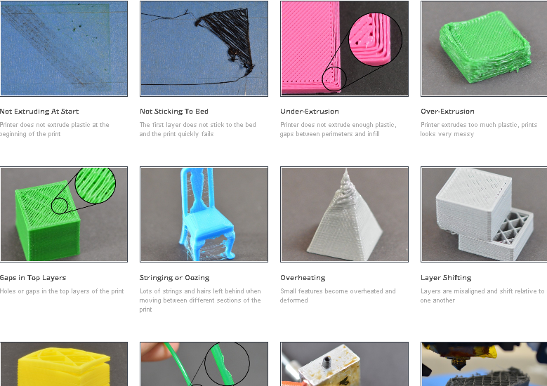
Enabling retraction is one of the more widely used solutions to stringing. This is a common 3D printing problem characterized by having very thing strands of filament or “strings” that ruin the aesthetics of the final print. Other symptoms of over-extrusion are blob in the final print or frequent jamming of the nozzle.
Some filaments are more prone to stringing than others. Good examples are flexible filaments such as TPU or TPE and filaments that print at very high temperatures such as Nylon. When working with these filaments, you can already expect to enable retraction to help avoid extrusion-related issues.
The standard settings for retraction are distance, speed, and minimum travel distance. Just about every 3D printer or slicer has these options. You can also choose to enable or disable retractions. Some slicers offer finer control over retraction performance via more advanced settings. Although retraction is generally beneficial, setting the parameters to very high values can also lead to other problems.
Retraction distance
The most basic setting in retraction is the retraction distance. This refers to the length of the filament that is pulled back by the extruder during retraction. Retracting a greater length of filament generally causes better pressure relief in the melt zone. However, excessive retraction can also damage the filament and cause other extrusion issues.
The standard recommendation is to set the retraction distance at 5 mm at the start and adjust as necessary. If stringing is still observed, then increasing the retraction distance by 1-mm increments can be done. Only increase this until no more stringing is observed. It is rarely necessary to set a retraction distance higher than 7 mm.
Another rule of thumb is that printers with Bowden extruders will typically require a higher retraction distance compared to those with direct extruders. This is because of how far the extruder gears are from the nozzle – a unique characteristic of the Bowden extruder design. The difference isn’t a huge value – an additional 2 mm can give good results.
Retracting very long segments of filament can make filament damage more likely. This is more specifically known as “filament grinding” and happens because a segment of the filament goes through the extruder gears too many times. For this reason, setting retraction distance too high is generally not a good idea.
Retraction speed
The retraction speed refers to the speed at which the filament is pulled back by the extruder gears. Retracting at a high speed makes oozing or stringing less likely, but it can also significantly increase the likelihood of filament damage.
The rule of thumb is to use the fastest retraction speed setting that does not damage your filament. An easy way to tell this is to check for any filament dust around the extruder during retraction. This is a certain sign that some filament grinding is taking place. If this is observed, then reduce the retraction speed by 10 mm/s increments.
Setting a faster retraction time should more readily resolve stringing and reduce your total printing time. We recommend limiting retraction speed settings to within the range of 40 to 70 mm/s.
Minimum travel distance
The minimum travel distance determines the distance that the print head will travel before the retraction mechanism activates. The setting in the slicer is the minimum value. Controlling the minimum travel distance avoids repeated retraction, especially if the print head is just crossing over very short gaps.
The goal of setting a minimum travel distance is to retract the filament only when necessary. By now, we already know that excessive retractions can result in filament damage.
The common default value for the minimum travel distance is 2 mm. You can try increasing this by 1-mm increments as long as oozing or stringing issues are not observed. A higher value for this setting is preferable, as it means that you do not retract the filament unnecessarily. This makes filament damage less likely and reduces the total printing time.
Combing mode
This is one of the more advanced retraction options that are popularly available in Cura. Combing is a feature that attempts to reduce retraction by directing the print head to move only along a path that has already been filled or will be filled later on. Along this Combing path, there will be no retraction. Ultimately, it does not matter because any stringing effects will be hidden in the final print.
Enabling combing has the advantage of massively reducing printing time by disabling retraction in sections where it is not necessary. However, it can also compromise the appearance of the final print when used inappropriately.
The standard practice is to enable Combing Mode but set it to only “Only Infill” or “Not in skin.” With this setting, combing will only happen when printing the infill pattern of your print. This retains the pristine appearance of your final print while reducing printing time and avoiding filament damage.
Maximum retraction count
The maximum retraction count is a more refined means of controlling the number of times that retraction can happen over the same segment of filament. Although this parameter can be indirectly controlled via the retraction distance setting, the maximum retraction count puts a hard limit on the number of retractions.
Should the slicer reach the maximum retraction count, it will disable retraction for that particular length of the filament. The goal of this is to avoid filament damage caused by excessive retraction.
In setting the maximum retraction count, you want to strike a balance between the possibility of filament damage and that of issues like stringing or oozing. Ideally, the slicer would never have to implement the cap on the number of retractions. A setting of 10 retractions is typically enough to attain this state.
If you are having problems with filament damage despite the settings we have recommended above, then limiting the maximum retraction count to a lower number can be an option. Try to be conservative when making this move – reducing by 1 at a time seems just right. We do not recommend going below 5.
Limit support retractions
This is simply a toggle-box available in some slicers. When ‘limit support retractions’ is enabled, the slicer will no longer instruct the extruder to do a retraction when printing support structures. Since these supports will just be removed anyway, this can be a huge help in reducing print time. There are typically no issues when enabling this option, so keeping the box checked is generally recommended.
Looking outside retraction
If you’re having problems with stringing or oozing, then retraction should not be your only solution. It’s more sensible to deal with the fundamentals first. Are you sure that you are printing with dry filament? Is your temperature within the recommended temperature range? Either one of these factors can also contribute to stringing.
Keep in mind that retraction does come with considerable drawbacks. If you can minimize retraction by fine-tuning your other slicer settings, you can save a lot of time and potential headaches.
Testing your retraction settings
Getting the best retraction settings can be tough, especially if you have to work with a new filament. We often recommend doing a test print just after you have dialed in new settings for your slicer.
For retraction, we recommend either one of these two models – the four triangular pillars or the two circular columns. Both are free to download and are fairly small models that will allow you to test the stringing performance of your printer with minimal filament usage.
Final thoughts
Retraction can be a very powerful tool in 3D printing if you can learn how to use it optimally. The key thing to remember is that it’s not a magic pill that will solve all your over-extrusion problems. Not only does it have a few drawbacks, but it’s still better to focus on your fundamentals first before relying on retraction.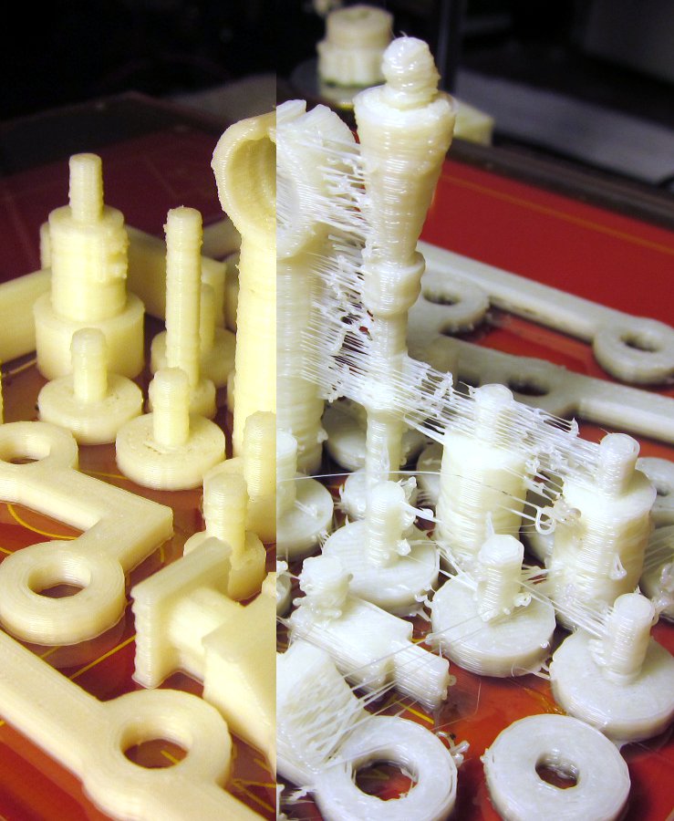
Most slicers will offer options for adjusting the retraction speed, distance, and minimum travel distance. These are usually enough to get the retraction mechanic to work just right for your project. Other slicers offer more advanced options. These are similarly useful, but not always necessary.
Warning; 3D printers should never be left unattended. They can pose a firesafety hazard.
The Insidious Problem of 3D Print Retraction « Fabbaloo
By Kerry Stevenson on October 10th, 2015 in learning
Tags: printing, simplify3d, tips
A common problem encountered with plastic extrusion 3D printers is stripped filament. We explain how this happens.
If you’re new to 3D printing and using a machine with the plastic extrusion process, you may find some 3D models very challenging to print. In some cases, they may seem impossible to print, because you keep stripping the filament and printing fails.
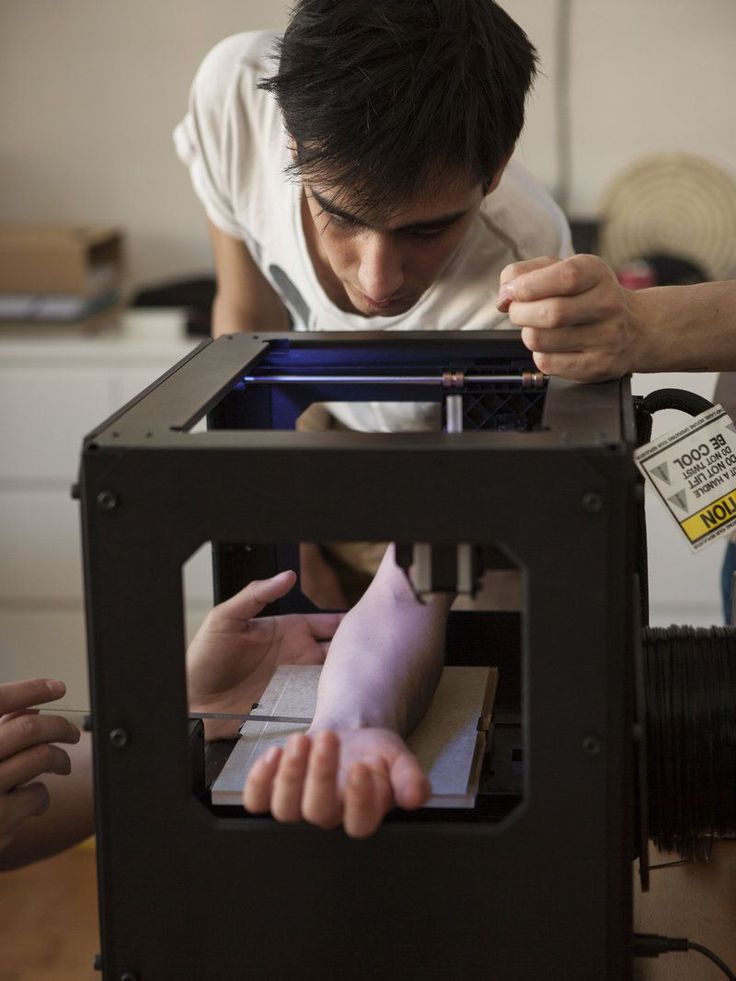
What’s a stripped filament? That plastic wire that feeds into your 3D printer is usually powered by a small toothed wheel that grips the side of the filament and pulls it off the spool and pushes it towards the hot end. Normally this process works quite well, as the tension between the wheel and the filament ensures a “good grip”. You can see how this works in the graphic at top: the extruder wheel grabs the filament with its teeth.
During printing, the extruder wheel may change speeds during printing, or even stop pushing if the hot end must jump from one spot to another.
It’s this jumping that can cause problems. By moving from one spot to another without extruding, you’d think nothing comes out of the hot end. But that’s usually not the case, as the heat of the hot end may result in a very small drip of fluid plastic. This drip becomes a “stringy” when the extruder jumps from point to point. Prints having many jumps will often be covered in thin, stringy plastic like cobwebs. Removing them is quite tedious and depending on the geometry, sometimes impossible, such as you can see in our stringy Eiffel Tower model here:
There is a very common technique to avoid “stringy” prints: retraction. In this method, the extruder motor is put in reverse for a brief moment to “suck up” the drip before it falls out of the hot end. This can, if properly tuned, eliminate stringy prints entirely.
But there can be a problem if there are repeated retractions, which can happen if you have a great deal of non-printing movements in rapid succession, such as would happen if printing this 3D model above. (It’s a pathological support structure for demonstration only; Don’t EVER DO THIS!)
As you might imagine, there would be countless retractions occurring during the printing of the lower portions of this pathological 3D model.
During these endless retractions, it’s possible that the gearing on the extruder wheel may become slightly out-of-line with its previous indentations in the filament. If so, it can squash the remaining filament and thus lose its ability to grip the filament.
Once grip is lost, subsequent retractions will simply polish the dead spot on the filament, resulting in a complete stoppage of printing, since the filament can no longer move. Your print might look like the image above: abruptly ended on a random layer, usually one with a lot of jumps, as is clearly the case in this Eiffel Tower print. Below we see an example of a filament stripped.
What can you do at this point? Well, nothing; your print has failed. You’ve wasted any material used up to that stage of the print and you must restart the print job.
What can you do in the future? It’s possible to turn of retraction in most slicing programs, which can avoid this scenario completely. But it comes at a cost: stringy prints. Another approach is to set a retraction limit, which indicates the minimum amount of printing that must occur before a second retraction can occur.
Depending on the geometry of your 3D model, you might need to play around with these settings to achieve the optimum successful print. Another option that’s possible in some slicing programs, such as Simplify3D, is to assign two different printing configurations: one without retraction for the lower portion in our pathological example above, and another for the upper portion that includes retraction to ensure the model prints clean.
As you can see, 3D printing is not always a matter of “pressing the print button”. For all but the most simple geometries, you likely have to do some analysis and parameter tweaking to ensure print success.
Kerry Stevenson, aka "General Fabb" has written over 8,000 stories on 3D printing at Fabbaloo since he launched the venture in 2007, with an intention to promote and grow the incredible technology of 3D printing across the world. So far, it seems to be working!
View all of Kerry Stevenson's posts.
3D printing defects - Let's try to introduce classification
Good afternoon, dear visitors of the portal.
Today I decided not to go into the artistic part of our work, but again into the scientific one.
By coincidence, I graduated from the university with a degree in foundry engineering. Why am I mentioning this: firstly, for the last 10 years, the foundry has been threatened that it will die due to stamping and 3D printing. Secondly, foundry uses a lot of its own terminology. Today I want to try to describe the main defects in 3D printing, possible names and ways to deal with them (defects, not names). Of course, within the framework of one article on one portal, we will not introduce our own terminology, but at least there will be something to discuss. I invite you to read and adequately comment.
Defect : Warp
Commonly used description: Peel off platform, bend
Description : Geometry distortion. Due to the transition of plastic from one state to another (liquid - solid-liquid - solid) and temperature changes, the plastic begins to decrease in volume. This process is uneven - first the edges cool down, and then only the central part. Because of this, internal stresses arise that tear off the edges or break the part.
Now some physics and explanation. It is IMPOSSIBLE to get rid of thermal shrinkage or shrinkage. This is a physical process - you can only compensate for it. In addition, remember - shrinkage of 0.5 -0.9% is mentioned everywhere. But this is only linear, which means you will have more volume.
How to fight:
- Reduce fill - less plastic, less to shrink - less tear force.
- Use a hot table - you heat up the lower layers, which gives an even distribution of stresses inside the part.
- Outline - You can print an outer layer around the part. This creates a kind of thermal barrier around the part, thereby maintaining the temperature throughout the volume, resulting in an even distribution of stresses throughout the part. An alternative is a closed build chamber, serving in the same way
- Use structural elements - First, check that your part is lying well on the table - if your flat side of the part is not flat at all (in art it's easy - to move a couple of polygons or vertices to the wrong place on a couple of mm), then it will easily come off.
 Secondly, if you understand the physics of the process, you can either add material somewhere, or make a hole in the part, etc. In this way, you will artificially cause stress redistribution in the part, however, this method is extremely complicated.
 - Increase grip strength - you don't have to fight stress, just provide the required grip strength. However, this option does not seem very good to me - these stresses will remain and your part can then be easily broken in this place.
Defect : Skewed
Frequently used description: Layers floated, the vertical is not respected, the layers do not lie exactly on top of each other
Description: Several variants of this defect are possible. Either the layers just lie unevenly, or the model is printed somehow in pieces, or just a slight skew. This defect is usually associated with the mechanical part of the printer. Due to friction, the actual path of the print head does not match the one that was loaded into the machine.
How to fight:
- Check the belts. Since there are many designs, it is difficult to give a universal answer here. Check that they lie normally at the points of contact and are not frayed anywhere. Look at the printer's instructions or some tips on the Internet - it is quite possible that the problem has already been sorted out before you.
- If the printer simply shifts the layers relative to each other, then it is possible that the pulleys are not fixed properly. With a black marker, you can mark the position, and after printing, compare and tweak this place if necessary.
- Move the print head without power - it should move without significant problems. If this is not so, then maybe it is worth finally lubricating the shafts?
- Squareness not ensured - again, due to poor mounting, the X and Y axes may not be perpendicular. This can lead to this defect, which means it's time to climb into the printer again and twist.
- Check the print platform - the glass may start to slide on your printer.
 And just like that, in the same direction. In this case, it is necessary to ensure its fixation in some way.
 - Electronic problem. Rare case, but possible.
Defect : Boiling, Puffiness (?)
Common Description: Holes in top layer, problem with outer layer.
Description : Protrusions on the upper layer of the part - can be either open or closed. In fact, this is due to the sagging of the plastic, which does not have time to cool when printed in the air without supports. Considering that there can be several such layers and all of them are of poor quality, we get this defect.
How to fight:
- Provide cooling - your plastic should cool well on the top layer. According to the recommendations, at this stage, cooling should go as much as possible.
- Ensure sufficient layer and wall thickness - In addition to sufficient cooling, you must have the required number of layers.
 Again, according to the recommendations, your wall should consist of at least 6 layers of your thickness. Thus, when printing with a layer of 0.1 mm, you want your wall to be at least 0.6 mm. But remember - too thin base layers will not work either - they simply will not hold themselves and other layers.
 - Try changing the occupancy - some slicers change the occupancy configuration at a certain percentage of infill, so the difference can be even between 24% and 25%. In addition, with a larger fill, the distance that is printed in the air is smaller, which can also remove this defect.
Defect : Lack of layers (?)
Commonly used description: Round things do not come out round, parallel straight things do not come out parallel
Description : Sometimes the geometry of the layers is not observed - this can manifest itself in circles, when the circle is not perfect, as well as in parallel lines. For example, parallel lines first diverge a little, and then, on the contrary, slightly overlap. This is due to the belts going to the stepper motors - most likely they are not fastened tightly enough.
How to deal:
- Tighten the straps near the print head - how to do this is best to look at the 3dtoday portal or ask your 3d printer supplier.
- Check that all fasteners are tight - use the tool that most likely came with your kit to do this
- Lubricate the guides - literally add one drop of light lubricant to your guides.
Defect : Elephant Leg
Commonly Used Description: Thick bottom layers, uneven layers at base.
Description : The effect when the bottom layers of your part are larger in area than they should be. Due to the fact that the nozzle at the beginning of printing is firmly pressed against the printing table at the beginning of printing, the layer begins to smear a little, thereby decreasing in thickness, but increasing in area. Then the print is evened out, because there is no longer a tight pressure
How to fight:
- Adjust the table - your nozzle should not rest against the print platform - there should be a slight, but still gap.
- Reduce the table temperature - a slight decrease in the table temperature can also reduce this defect. Do not get carried away with these methods too much - this may degrade the overall print quality.
- Structural model improvements - add small chamfers or fillets. You will have to play around with the settings a bit, but thanks to such a design improvement in the model, your model will be smooth and beautiful. However, it is impossible to say for sure which chamfer to make. Start with a 0.5 x 45 bevel, and then empirically find the best option.
Defect : External slack (?)
Common description: Snot, plastic between two parts part to another, a long, thin layer of plastic is created that spoils the outer shape of the part(s). This is due to the fact that the plastic that remains at the tip of the nozzle under the influence of gravity and friction is caught on one part and begins to drag through the air. Depending on the fluidity parameter and the hardening time, different plastics exhibit this defect in different ways.
How to fight:
- Use the retract function - thanks to it, the print head will slightly return the plastic, thus removing it from the tip of the nozzle. This setting is activated directly in the slicer (if it supports it). In the Cura slicer, the retract is drawn with thin blue lines and you can check this moment at the level of the finished task.
- Increase your print speed - the physics is simple - by increasing your print speed, you reduce the amount of time the plastic can catch on your part. However, increasing the print speed is not always possible and may cause other defects.
- Change the print temperature - print temperature has a direct effect on fluidity, especially with PLA.
 Reducing the temperature even by 10 degrees significantly reduces the effect of external sagging.
Defect : Waviness
Commonly used description: Discoloration at the edges of the part, defects along the edges
Description : This defect appears as darkening and slight waviness around the sharp ends. If you start typing the text, it will look like a slight shadow effect on it. This is due to the inertia that is imparted to the liquid plastic during printing. Regarding plastic, the print head has a large mass and during a sharp change in direction, liquid plastic is not able to sharply repeat the trajectory, which causes slight waviness in the corners.
How to deal with:
- Decrease print speed - Decreases print speed, reduces sharpness at corners, thereby smoothing the effect.
- Decrease print head acceleration - these settings are not available in all slicers, however, this will eliminate the defect without reducing the print speed.
- Change the print temperature - as we mentioned earlier, temperature affects fluidity, so lowering the print temperature can help get rid of the defect.
Defect : Looseness, Sagging (?)
Frequently used description: Snot on the part, sagging plastic on the part
Description: One of the most common and basic defects in plastic is due to printing in the air sags instead of getting a flat horizontal surface. This is due to the fact that the plastic does not have time to cool down and is printed without support where they are needed. Sagging can occur for many reasons, although the physical nature of the defect is practically unchanged. Because of this, the elimination of this defect may not be obvious.
How to fight:
- Cooling - Depending on the plastic, you may or may not need cooling. If it is necessary - provide it as much as possible.
- Print more than one part - for small parts, printing more than one part will help a lot.
 This will remove the heat source and give your part time to cool.
 - Work with the thickness of the layer - it is not possible to make a recommendation whether it is better to increase the layer or reduce it. Each situation must be decided, however, changing the thickness of the layer can improve or worsen the effect of sagging.
- Reduce print speed - very often reducing print speed can improve the quality of your part.
- Reduce temperature - if you decrease the temperature, the plastic will cool faster to a solid state. However, do not lower the temperature too low, otherwise the print quality may drop.
- Reposition the part - if possible without loss of quality, try to position the part differently. Stop, think, or use auto-positioning (like Meshmixer). Instead of fighting a defect, you can often simply eliminate it.
Defect : Layering of the bottom layer
Commonly used description: Clearly defined bottom layer, thick lines of the bottom layer
Description : Printing the bottom layer is one of the most important moments in printing. If we print too close, we will get an elephant leg defect. In the case of a large gap, we can get excessive layering of the lower layer.
How to deal with:
- Decrease the thickness of the first layer - many slicers have the ability to change the first layers of printing. Try to make it smaller to achieve a result that suits you.
- Recalibration - many problems with the bottom layers can be solved by recalibrating the table. Set the distance a little less and you might get the desired result.
Defect : Underextrusion
Common Description: Holes in Print, Layer Problems, Surface Defects
Description : Underextrusion is a defect worthy of its own article with a description. It can occur as a result of a huge number of factors, both related to the printer and plastic. It is very easy to observe it - the surface of the part comes out not even, but with all sorts of inclusions, or vice versa, the absence of plastic where it is needed. To eliminate this defect, an integrated approach may be required.
How to deal with:
- Change the speed - your printer may not technically be able to print at this speed. You may need to lubricate it or change the plastic, but first try printing at a slower speed. In addition, not all parts and not all plastics, the printer can print at maximum speed
- Change the temperature - all plastics have recommended temperatures for printing. If you print at the wrong temperature, then you do not provide the required fluidity parameters for working with this plastic and you will not print correctly with it.
- Check plastic - plastic may be damp, dirty or of poor quality. All this can lead to under extrusion, or that you will not print at all. In addition, plastic can break due to the feed mechanism and its strength properties. You may not be able to print with this plastic. Or maybe his diameter is walking .. As you understand, changing the plastic to another will allow you to quickly understand the problem in the printer or consumable.

- Check the paper feed mechanism - if you are working with soft plastic, the plastic may creased too much, which will prevent you from printing properly. Then, most likely, it will be necessary to loosen the grip of the bar, however, this should be done only after contacting those. support if you are doing this for the first time.
- Check the bar - during printing, sometimes your bar may become knotted or something is preventing it from entering the extruder. Be sure to check it out right now.
- Change or clean the nozzle - your nozzle will not last forever. In the course of work, it will become dirty - both from the soot of plastic, and from the dust that you allowed. Always have a pair of replacement nozzles available to help you understand this problem. In addition, when you refill plastic with a lower printing temperature, print at a high temperature so that the remnants of the old plastic completely come out and do not interfere with work.
- Check slicer settings - some slicers may use nozzle retraction and nozzle cleaning to get rid of external slack.
 Because of this, when you return the print head, you do not immediately start feeding plastic. This can lead to underextrusion in some parts of the model.
 - Check the Teflon tube - due to dirt allowed in the printing area, the Teflon tube may become contaminated. Because of this, the rod will experience friction, which will lead to underextrusion.
- Check the gears - if the gears that grip the bar do not work properly, then it will be problematic to exit the nozzle. If simpler measures do not suit you, check that this mechanism works correctly.
Defect : Notches (?)
Common description: Walls do not fuse together. Hollows in the walls.
Description: Mechanical problem. Due to the limited path of the printing part, there are voids and inconsistencies between the walls. Contact may be partial or absent entirely.
How to deal:
- Tighten the straps near the print head - how to do this is best to look at the 3dtoday portal or ask your 3d printer supplier.
 This option is best used in case of partial contact.
 - Reduce the print speed - plastic may not fit well at this speed. A slight increase in temperature may also help.
- Change the wall settings - this problem may arise due to the principle of laying this very wall. If you have a 0.3 nozzle, then it is impossible to lay a 1 mm wall in ideal layers of 0.3 mm. So the program can either represent the wall as 0.9mm and lay 3 layers, or somehow compensate for this. Try changing the wall thickness and maybe you can get rid of the defect.
Defect : Scratches
Commonly used description: Surface scratches and color unevenness
Description : During the movement of the surface, the print head leaves a mark on the plastic due to close contact with the plastic. This can be either grazing old plastic or smearing new plastic that flows out of the nozzle due to contact.
How to deal with:
- Increasing speed and decreasing temperature - as in other similar defects, when plastic leaves a mark, increasing speed and decreasing temperature can reduce the effect of this problem.

- Slicer setting change - To a large extent, this defect can be controlled by the slicer. Using Cura as an example, you can use the z-hop function (raises the nozzle). In addition, you can work on the retract.
- Change in geometry - this defect can still appear on complex surfaces. Try adding an even layer to your model or simplifying the geometry altogether if you're having this problem and it's making your life worse.
Defect : Underfill
Common Description: Part prints strangely. Incorrect entry of the part. Print supports where they shouldn't be
Description : The type of defects associated with the electronic model - can be associated with many things. If the polygons have incorrectly directed normals, if the model is not fully stitched (there are holes) or consists of several elements - all this can lead to this type of defects, when the slicer will misunderstand what they want from it.
How to fight:
- Check the model in Netfabb/Meshmixer - with the help of specialized products you can check the model and see what errors it has. These programs eliminate many of the problems that were made before printing. However, these programs may distort your geometry.
- Fix the electronic model - if you have the skills and the ability to use the functionality of 3d programs to fix the mesh. Sew the meshes, close the gaps, reverse the normals, then check the resulting g-code. In it you will see how your model will be printed and whether everything suits you.
Defect : Fluffiness
Commonly used description: Model as in hair. Snot. Sagging.
Description : Reduced external sag. Small hairs stick out on the model, which remain from the printing nozzle. The physics of the phenomenon is the same, but the amount of plastic is much less. However, this defect can occur even if the nozzle does not move from one object to another.
How to fight:
- Check the plastic - your plastic may be dirty or poorly made. Try a different plastic and you may be able to get rid of the
- Check the nozzle - this fluffiness may be the first sign that something is wrong with the nozzle. Check the outside of the nozzle to make sure nothing is sticking out or try a different nozzle
- Remove the defect after work - this is the rare type of defect that is quite easy to get rid of by post-processing. Use a sandpaper, needle file or other handy tool.
Defect: Skipped layer
Common description: The layer is different from the other layers in the model. The model is flaking into pieces
Description: The case when one or more layers differ from the others. Then comes stable printing and the defect may recur. May be due to underextrusion or machine problems.
How to deal with:
- Familiarize yourself with underextrusion - it is possible that you will see more similar defects and you will know how to proceed.
- Lubricate the Z-track - since the table moves in the Z direction, it is possible that in some areas you have accumulated dirt or lack of lubrication. Lubricate the guide as recommended by the manufacturer and check operation.
- Bearing problem - it is possible that the problem is not in the guide, but in another element of the lifting mechanism. In this case, you need to check the bearing adjustment or return the printer for service. Look for more information on the portal 3dtoday
- Too much lubrication - too much lubricant - does not mean better. It can start to easily accumulate dirt and again begin to cause this effect. Wipe the shafts and lubricate with the necessary amount of material.
- Electronic problem - it is possible that the problem is not with the mechanical, but with the electronic part of the movement. If other methods do not help, then most likely the printer may need to be returned for repair.
- Defective parts - unfortunately this happens.
 It is possible that everything is done well, but some part of the mechanism is out of order. Again, this cannot be solved without disassembling the printer.
Defect: Misalignment of axes
Commonly used description: No right angle.
Description: Cases where the mating parts of the mechanism do not fit into the grooves due to misalignment. Another way to identify a problem is that the printer head moves with force.
How to fight:
- Editing axes - the defect is eliminated only mechanically. Ask the supplier or manufacturer for information on how to correct the axes and then reconfigure the printer.
I do not claim to be the final authority. For my part, I would like an adequate discussion and proposals in order to supplement and develop this article and formulate it into a finished version. Icons? mean that I still do not consider this name final and I expect other proposals for names from you. Only the names should be sensible so that a person imagines what it is and uses a short word to define it. It is better to mark grammatical and lexical errors in my personal - I hope we will agree with the editors so that they give the opportunity to correct the article. The material is based on this source. I did not specifically add some defects that are not related to the plastic, the printer and the printing mechanism (such as the detachment of the part from the table and the poor performance of the electronics), although you may say that it is more logical to add. In short, ready for discussion.
Sincerely, Sergey Panin
Problem with extrusion? You are here / Habr
Do you know what a real universal fakap is? Recently, I fully felt it in my skin. I hope the text will be useful for novice 3D printers, since the problem is not an isolated one, but it was not easy to find a solution, and even I, an old atheist, almost believed in miracles.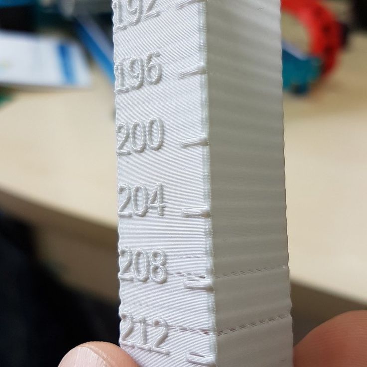 Forgive me for the presentation, since I am not a writer or a blogger, but a simple engineer - a firm engineer.
In addition, the text is intended for people with minimal experience with 3D printing.
Solely for the reason not to inflate the article and not explain the purpose of various details and slang words. I'll start with the backstory. A little less than a year ago I bought myself an inexpensive 3D printer. One of the most popular (not as advertising, but to make it clear what it is about) is Ender 3. The assembly was simple, there are many recommendations on the Web. Of course, assembling it according to the instructions, I would have received a non-working unit, but after “smoking the manuals”, I managed to complete the first test print for 5 plus for such a simple machine! Everything was fine up to a certain point. But then it began ...
If you're interested, welcome.
For those who are too lazy to read:
The extruder pressure roller arm has broken.
The printer was needed for a specific task - printing non-standard cases for various small-scale electronic crafts. After I played enough with ready-made models and provided my daughter with various little animals and little men, I mastered FreeCAD “on top” and began to do useful things. Everything went well ... By and large, the print was launched "from the foot", set it and went to bed. Unless the first layer controlled. But the first "bells" appeared.
Somewhere part of the layer will fall out, somewhere the plastic will burn. I calibrated the table “according to a piece of paper”, sinned on the plastic and the nozzle, changed the settings in the slicer, plastics and nozzles - the problems disappeared. Bye…
At one "wonderful" moment, I ran into an "insoluble" problem. The end of March, a smooth transfer to a remote location (I successfully moved from the Moscow region to Minsk 2 years earlier), I decided to assemble a separate computer for work from what I had.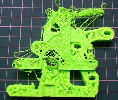 In the stash was a good motherboard, processor, a couple of monitors and 2 cases. One is a huge full-fledged ATX, the other is a barebone. I decided to collect in a small one, so that it takes up less space. The case is non-standard. With cradle for 1 CD drive and 3.5 inch hard drive. I found 3x 2.5 SATA SSD of small volume, for the system and one is enough "more than" and 1x for 1Tb 2.5 HDD.
All this "living creatures" was placed in a large building on a makeshift adapter from old bank cards. But, since a printer has already appeared, it would be nice to use it. I created a holder model, put it on print and went about my business. When I looked at how it prints, I saw only noodles ... From that moment on, the path of repair went, 2 months long. I will try to paint on the shelves, what helped and what did not, and what was the root cause.
Step 1 Adjusting the rollers {prevention is always good}
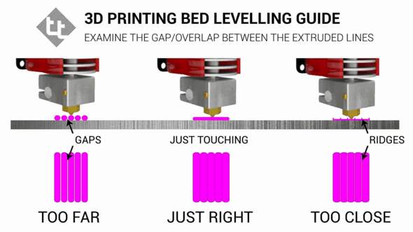
Once again, I set up the table “on a piece of paper”, launched it - the plastic does not stick. I changed the settings, plastics - without result. Instead of sticking to the table, it bends onto the nozzle. When I rechecked the nozzle gap settings, I found that the rollers were loose and the table had play by almost 5mm at the edges. It's strange how he used to print at all before ... It seemed that the reason was found. Adjusted. But it didn't get any better. With grief in half I printed the part, but the quality left much to be desired:
Obvious gaps in print are visible.
And here are the bundles…
Step 2. Song of Ze[l]de {it's good when everything goes like clockwork}
The first thing that came to my mind was the problem in the Z-axis drive. And all the advice on the forums on a problem similar to mine pointed to this. Took it apart and checked for smoothness. The nut bit the thread a little and found a “bug” in a couple of rollers. When moving without the drive screw, the "X" rail stuck a little for 1 turn of the roller. I ordered a drive nut, rollers (spare parts are always good, but that was not the point). Using the method of combinatorics and some kind of mother, I distributed the axle rollers according to the loads so that the defective ones had minimal effort. The "bite" is gone. Cleaned and lubricated the drive screw. Adjusted the position of his engine. As a result, a light touch of a finger is enough to lower the carriage down. The result is negative.
Step 3. Slicer {tuning, but not solving the problem}
Updated slicer. Moreover, the new release just had an improvement related specifically to the print quality for my printer. Played around with flow and speed, layer thicknesses, etc. Even successfully printed some simple small cases and parts. But the settings were frankly wild: flow - + 10%, speed - -5%. Considering that after assembly, excellent printing was obtained at the “default” settings. The problem of printing complex parts has not disappeared . ..
..
Based on this article: https://habr.com/ru/post/494058/ I made a brushing timer for my daughter. I am preparing a separate description for it. Spoiler: eight-legged controller, firmware - 119 assembler commands.
Step 3. Extruder {and happiness was so close...}
Logic dictates that since there are no problems with the geometry and drives of the axes, there must be something with the feed. Removed the filament feed gear and cleaned it. No visible wear is observed. I returned it to its place, slightly shifting along the flight, to even out wear. The result is 0. Eh, if I look a little to the right, I would save a month of nerves and $ 200.
Step 4. Checking the SD drivers {no comment}
Excellent geometry, no problems with the mechanics. At the time of the first assembly, everything was much worse. A bunch of studied materials, improvements and settings, and the result is zero. I do not believe in miracles, electronics remained. Moreover, members of the forum often complain about burnt drivers. It is clear that a completely burnt out shoulder of the bridge can be detected “by eye” immediately, I thought about a “floating” malfunction. After all, the plastic lays down normally, then - passes, the thread becomes thinner, hair and other charms. I ordered an improved control board on ARM, but in order not to waste time, I decided to check the existing one. I removed the board, the Z-axis motor as an inductive load, assembled the stand on the table, set the temperature of the hot end with a resistor so that the extruder could be rotated. I looked at the waveforms on the SD coils. Everything is great. He warmed the driver with a hairdryer (a crystal defect or unwelding sometimes manifests itself), mechanically acted on the driver IC, cooled propane with butane (gas for lighters). Note. It cools quite well to -20, it is not necessary to buy an expensive freezer for this.
 Everything is great. Failures are not visible!
Step 5: Firmware update No, I am sure that miracles do not happen. There are bugs, glitches, tricks, lack of information, subjective perception of reality, after all. But not miracles! But how to explain that, with good mechanics and electronics, printing behaves extremely strangely? The Chinese made a bookmark in FW in order to additionally barry with boards? It is done elementarily, but, I think, they would have been discovered long ago and a white fluffy fox would have come to the trademark. Bug in the firmware? Everything is possible, only somehow it manifested itself strangely.
EEPROM settings wrong or FLASH* "bugging"? Most likely. Okay, since the board is on the table, nothing prevents it from being reflashed. Updated to "vanilla" Marlin 1.1.9, collected everything back. The result is that the miracle did not happen.
*Purely theoretical justification for the possibility of linking the problem with FLASH memory:
Let's say we have the following code fragment:
…
const uint8_t step = 0x18;
…
position += step;
…
At each iteration, the “step” setting is added to the current position. Since the program is executed on a microcontroller (MK), the code and constants are placed in ROM and can only be changed during an external programming procedure (we will omit the possibility of reprogramming the FLASH memory by internal means of the MK). This procedure is performed once by the manufacturer. Now 2 important points: the controller processor reads commands and constants from ROM every time, forget about caches, Atmega does not have them. That is, if the loop went through 1000000 iterations, then the constant was read the same million times. With each read, FLASH degrades a little. I don’t know what the critical reading threshold for NOR is, I think it’s tens of billions, but TLC NAND already degrades quite well after 10-20K readings ... The second point is not the fact that our narrow-eyed friends did not use rejected controllers. I actually got one like this. PICs. Not soldered, but there are strange marks on the case. FLASH was not erased, at 3.6V they did not want to be erased or flashed.
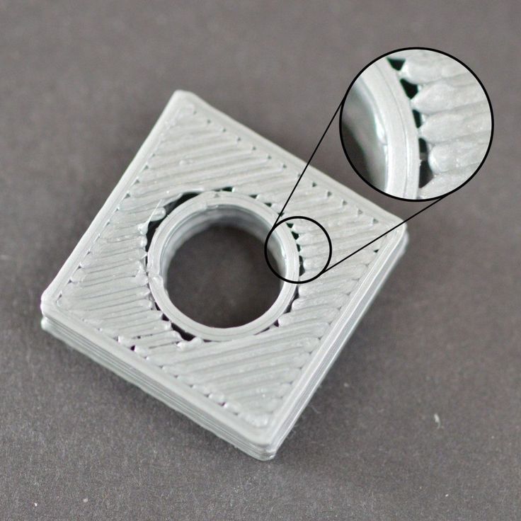 I had to raise it to 5V, after which the recording / verification began to take place. Let's say our constant was written to a defective cell. While the device is new, 0x18 was read stably. But from time to time (and for Atmega, the guaranteed time for saving data is not the longest) and degradation, at some point it began to read not 0x18, but 0x08. Not every time, but still. I know, rather than degrading 1 to 0, but vice versa, this is just an example. So, as long as the correct number is read stably, the movement occurs correctly, but when failures occur, an incorrect setpoint is added to the result, which leads to feed failures. This is the simplest and most unlikely example. There may be other glitches, for example, in the addition command, the source of R6 will change to R7. The assembler instruction remains valid, the processor will execute it, but the result will be incorrect ...
Step 6. Flush the “throat” {keep your head cool and the hot end clean, I recommend doing this immediately after buying a printer}
A gift from "heaven" was a link on one of the forums to a video from the manufacturer. There they honestly admit that not all hotends are equally useful, that is, they are well assembled.
Teflon tube not fully pressed in, cut uneven. The consequence is the formation of a cork and the extruder cannot normally advance the plastic. Here it is - my case!
Abnormal flow and retract values, everything converges. Despite late Saturday evening and a visit to a brasserie, I decided to check it out. Exactly. Guana is unmeasured there, right down to the remnants of the plastic that I used to print a month ago (the same green holder). Very likely to win! I cleared the “throat”, cut the tube evenly, pressed it in as far as it would go, also fixed the second end of the tube more tightly, many people use electrical tape, but I wound a little 0.7 wire, which allows you to freely unscrew the holder:
And here is the “killed” end of the tube, you can see that it was cut crooked:
The model is cut into layers with default settings. The seal . .. The border went, the contour went, there is no snot during the retract. Hooray!!! Victory!!! I was about to write an article so that others would not suffer, but ... A complete fiasco. Thinning and tearing of plastic, gaps in printing. Already ready to give up. The wife encourages, but you throw it away, buy a new one! I can't do that. There must be a reason. That's just where??? There were no more reasonable (and censored) thoughts ...
Remark about cleaning the “throat”:
All operations with the hot end are done only “hot”, otherwise there is a chance to break everything. After warming up, the first step is to remove the nozzle and clean it from the remnants of the “cork”. I did this by heating the nozzle on a gas stove flame and carefully removing the plastic. Didn't clean the inside. Then, also on a heated hot end, the tube clamp is unscrewed. He can only move up. After retracting the latch, the tube should be gently but with force removed from the “throat”. We remove all the latches, since the damaged end still cannot be saved, carefully, back and forth, we clean out all the dirt, constantly removing it from the tube. As a result, the tube should easily pass through the throat through and through. The assembly was performed by the FIFO sequence. First, I installed the nozzle, then the tube clamp in the hot end, but did not tighten it completely, leaving about 1 turn. The worn part of the tube is cut off at a right angle and inserted into the throat as far as it will go. After that, the holder is tightened and the second one is installed, on the opposite side of the "teflon".
Step 7. Feed Calibration {with good mechanics, most likely not needed unless after replacement of drive parts or flashing}
In the instructions for upgrading to the "vanilla" Marlin, it was said that for the factory printer all settings are ideal, but the accuracy of the plastic feed may be slightly off. Okay, let's calibrate.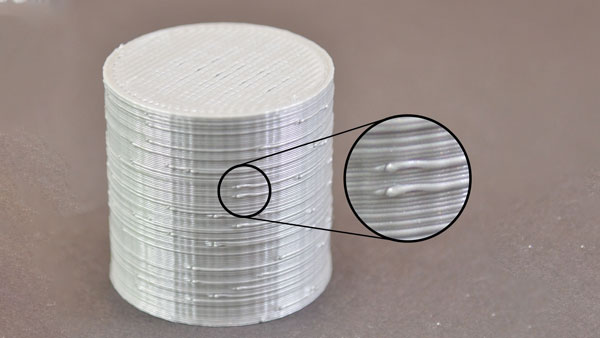 He pulled out the plastic, warmed up the hot end (there is a lock in the firmware, it does not allow you to move “E” to a cold one). I unscrewed the tube from the feed mechanism, cut the plastic flush and executed the 300mm extrusion command. I have a ruler at 350. Extrusion lasts long enough, upon completion, I measured the length of the released filament and could not believe my eyes 226mm. I understand the difference of 3-5%, but not 25%! I'll try another plastic...
Note. I saw how the feed is regulated according to the marks on the bar marked with a marker, But with cutting, IHMO, more precisely.
Preparation for test extrusion:
After extrusion:
We measure with a ruler, in my case (after repair) it turned out 292mm. Next, go to the menu: control / motion / step mm, see how many steps per mm are set for the extruder. In my case it is 93. Let's do a simple calculation:
>>> (300*93)/292
95.54794520547945
Change the setting and save the setting.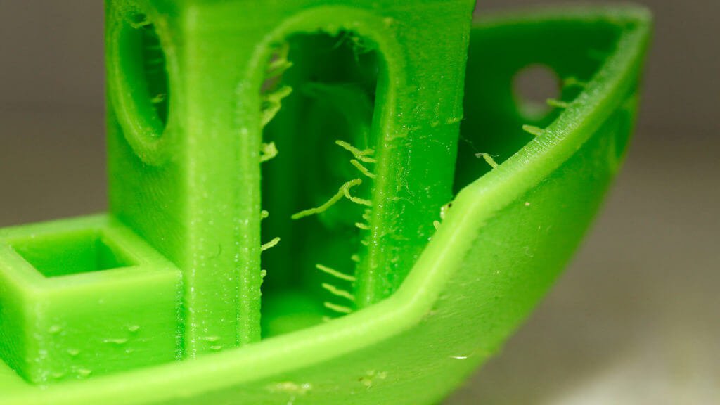 Re-extrusion - error at the measurement level.
Step 8. Victory!
At first I checked for PETG, I decided to change to PLA. The first one I overheated a little during drying, I attributed the inadequate spread to possible sticking on the coil. Cutting, extrusion. And nothing. Plastic is not supplied at all. The axis of the drive rotates slowly, but the screws show that there is movement. I looked, the bar did not lie correctly between the gear and the pressure roller. Okay, I'm correct. That the roller dangles a little. Gotta pull it up. And fig! Here he is the culprit of all my troubles:
The pressure roller arm is cracked. At the same time, the clamping force remained sufficient for partial advancement of the rod. Gear marks remained and the pressure roller rotated.
Accordingly, all games with the pressure spring setting were unsuccessful. The slips of the bar were invisible to the eye, and the crack could not be seen on the assembled mechanism. All! Engineer's ecstasy received! The lever was glued together, an aluminum mechanism was ordered, a spare was printed just in case (if it breaks while I wait for a new one). Here is a link to the model. Of course, it’s unpleasant to spend so much time and money over such a trifle, but it helped me dive much deeper into the processes of printing and catching glitches.
Actually, the first part after repair. Clamping lever:
Finally, my presence sensor found a "face". The case was printed even before the breakdown:
Attempts to print a “face” on a faulty printer (after cleaning the “throat”):
I hope this material will help at least someone not to make so many stupid attempts to find a primitive malfunction and save money. Of course, I did not deal with the problem every evening, but in total - a day, probably, was spent. For the money - about $ 200 for parts. The price of troubleshooting is 15 minutes and a couple of drops of "superglue".