Blender 3d printing essentials pdf
[PDF] Blender 3D Printing Essentials by Gordon Fisher eBook
About This Book
In Detail
Like computing, 3D printing has been around for decades but it was expensive and was only used for making complex prototypes. Now, prices have dropped and third-party printing services such as Shapeways have become available, making the technology available to everyone.
Blender is an open source modeling and animation program popular in the 3D printing community. 3D printing demands more of a modeler than animation or virtual reality. The model maker must engineer their model to work in the real world. They must keep in mind the particular needs of the materials and printers that they are planning to use to print their model.
This practical guide gives Blender users all the information they need to design high-quality 3D printed objects. With a solid exploration of the 3D modeling process, design considerations for 3D printing, plus step-by-step exercises, you will soon be comfortable making 3D objects for real-world enjoyment.
Starting with an overview of 3D printing, this guide moves onto to precision measurement, fixing problems in a 3D model, and how to make it light and strong enough for real-world use.
You will learn how to scale, build, and detail a model for a 3D printer. You will learn to color and decorate it, as well as making parts precisely in the size you want them, so that multi-part objects fit together smoothly. You will also learn tips on saving money when you have printed your model.
With the help of this guide, you will be able to complete your project and learn how to export the file so it is ready for a variety of 3D printers.
Approach
This book adopts a practical approach, with the use of step-by-step instructions to help guide readers. There are lots of screenshots covering each and every step needed to design a high-quality model in Blender for 3D printing.
Who this book is for
If you are a Blender user or someone who wants to use Blender to make 3D objects suitable for 3D printing, this book is ideal for you. You should already be comfortable with basic modeling in Blender - including using modifiers - although advanced skills are not required. All of the models that you will need are explored in-depth. This book does not assume that you will use any specific printer and teaches the general principles common to building models for most printers. It also gives you tips on discovering the requirements of the specific printer you will be using.
Information
Publisher
Packt Publishing
Year
2013
ISBN
9781783284597
Topic
Computer Science
Subtopic
Open Source Programming
Blender 3D Printing Essentials
Credits
About the Author
About the Reviewers
www.PacktPub.com
Support files, eBooks, discount offers and more
Why Subscribe?
Free Access for Packt account holders
Preface
What this book covers
What you need for this book
Who this book is for
Conventions
Reader feedback
Customer support
Downloading the example code
Downloading the color images of this book
Errata
Piracy
Questions
1. Designing Objects for 3D Printing
Opportunities to use your 3D printer
How a 3D printer works
Types of 3D printers
Basic parts of a 3D printer
How is a 3D printer controlled?
The Peachy printer
Modeling dimensions
File sizes
Polygon sizes
Factors affecting precision
Controlling printing costs
Materials for 3D printing
3D printing and your health
What happens at a 3D printing service?
Summary
2. Measuring and Texturing Techniques for 3D Printing
Precision modeling in Blender
Using the Ruler/Protractor
Using the Protractor
Measuring the thickness of an object
Preparing the model for coloring
Leaving the object uncolored
Vertex colors
Vertex painting
Building texture maps
Choosing colors for printing
UV unwrapping
UV mapping the wings
UV mapping the belly
UV mapping the edges of the wing
UV mapping the head
Painting the texture map
Exporting the UV Layout for use in an external paint program
Painting your texture in Blender
Modifying the UV coordinates to add detail
Using the Clone brush to add detail
Summary
3. Making a Blender Model that's Ready to Print
What is special about 3D printing?
Installing the Print3D toolbox
Introducing the Print3D toolbox
Introducing the Mesh Analysis panel
Setting up the units of the scene
Making a 3D model that will print
Making a watertight model
Making a manifold model
Inspecting objects to see if they are manifold or non-manifold
Finding problems that make a file non-manifold
Fixing noncontiguous edges
Typical problem areas with a model
Fixing distorted polygons
Blunting sharp edges
Fixing the junction between blade and hilt
Economizing when 3D printing
Summary
4. Making Strong, Light Objects with the Solidify Modifier
Optimizing wall thickness
Using Solidify for proper wall thickness
Analyzing and modifying the inner shell
Making the dragon useful
Cutting holes for removing extra printing material
Precision modeling—fitting two objects together
Dealing with overhangs and support
If the printer automatically makes supports
Making supports for your model
Exporting your 3D object
Getting the orientation right
Making an STL file
Making an X3D file with a texture
Summary
A. 3D Printing References
References
3D printing services
3D printers – hobbyist
3D printers – industrial
3D objects
Index
Copyright © 2013 Packt Publishing
All rights reserved. No part of this book may be reproduced, stored in a retrieval system, or transmitted in any form or by any means, without the prior written permission of the publisher, except in the case of brief quotations embedded in critical articles or reviews.
Every effort has been made in the preparation of this book to ensure the accuracy of the information presented. However, the information contained in this book is sold without warranty, either express or implied. Neither the author, nor Packt Publishing, and its dealers and distributors will be held liable for any damages caused or alleged to be caused directly or indirectly by this book.
Packt Publishing has endeavored to provide trademark information about all of the companies and products mentioned in this book by the appropriate use of capitals. However, Packt Publishing cannot guarantee the accuracy of this information.
First published: November 2013
Production Reference: 1141113
Published by Packt Publishing Ltd.
Livery Place
35 Livery Street
Birmingham B3 2PB, UK.
ISBN 978-1-78328-459-7
www.packtpub.com
Cover Image by Gordon Fisher (<[email protected]>)
Author
Gordon Fisher
Reviewers
Sandra Gilbert
Taylor Petrick
Acquisition Editor
Sam Birch
Commissioning Editor
Subho Gupta
Technical Editors
Novina Kewalramani
Harshad Vairat
Project Coordinator
Amey Sawant
Proofreader
Paul Hindle
Indexer
Rekha Nair
Production Coordinator
Nitesh Thakur
Cover Work
Nitesh Thakur
Gordon Fisher, as a teenager, studied drafting and built plastic model cars. He got his start in 3D computer modeling back when one would have to create a 3D engineering drawing with a pencil and then input the information into a computer, vertex-by-vertex.
He led a three-person crew in building 3D models of 80 aircraft for the U.S. Army Visual Aircraft Recognition program. He also built an accurate model of the 17th and 18th holes of the Pebble Beach golf course for Callaway Golf's golf simulator. He's currently working with the Open Luna Foundation to create models, X3D and 3D printed, of their parts of their proposed lunar base.
He is the Creative Director at Point Happy Interactive. He has been using Blender professionally since 2002 and has given classes on using Blender and using Python with Blender at Python conferences in Texas and Arkansas. His work has been displayed at the National Air and Space Museum. He is also the author of the book Blender 3D Basics, published by Packt Publishing.
Citation styles for Blender 3D Printing EssentialsHow to cite Blender 3D Printing Essentials for your reference list or bibliography: select your referencing style from the list below and hit 'copy' to generate a citation. DOWNLOAD E.B.O.O.K.# Blender 3D Printing Essentials *Full Online
11.06.2020 • Views
Share Embed Flag
pdf download Blender 3D Printing Essentials read Blender 3D Printing Essentials best seller Blender 3D Printing Essentials Blender 3D Printing Essentials txt Blender 3D Printing Essentials pdf Blender 3D Printing Essentials ebook Blender 3D Printing Essentials csv Blender 3D Printing Essentials doc Blender 3D Printing Essentials excel reading Blender 3D Printing Essentials Blender 3D Printing Essentials full book
pdf download Blender 3D Printing Essentials
read Blender 3D Printing Essentials
best seller Blender 3D Printing Essentials
Blender 3D Printing Essentials txt
Blender 3D Printing Essentials pdf
Blender 3D Printing Essentials ebook
Blender 3D Printing Essentials csv
Blender 3D Printing Essentials doc
Blender 3D Printing Essentials excel
reading Blender 3D Printing Essentials
Blender 3D Printing Essentials full book
SHOW MORE
SHOW LESS
- No tags were found.
 ..
..
Create successful ePaper yourself
Turn your PDF publications into a flip-book with our unique Google optimized e-Paper software.
START NOW
- More documents
- Similar magazines
- Info
Inappropriate
Loading. DOWNLOAD E.B.O.O.K.# Blender 3D Printing Essentials *Full Online
Save as template?
Description
no error
Modeling 3D model objects in Blender
In the article, the authors considered the possibilities of low-poly modeling in the Blender computer program.
Keywords: modeling, computer graphics, three-dimensional space.
The relevance of research. Today, such a field of activity as 3D modeling is very relevant and in demand in the life of society. This area is widely used in marketing, architectural design, medicine, cinematography, industry, game production, engineering design. Thanks to the ability to use methods and technologies such as 3D design, rendering, visualization and animation, it became possible to turn ideas into digital graphics on the screen, create a prototype of a future structure, a commercial product in a three-dimensional format. 3D modeling plays an important role in the presentation and demonstration of any product or service [1].
The relevance of 3D modeling is due to the fact that with its help a number of new opportunities appear that allow you to quickly and inexpensively produce prototypes of three-dimensional objects. The result of working with 3D modeling can be 3D models printed on a 3D printer. 3D printing technologies are becoming more and more part of our lives every year. Why buy certain tools or parts, especially if they need to be delivered to hard-to-reach places, when all this can be printed right on the spot. The area where 3D graphics is used is large: games, cinema and animation, construction, medicine, etc. [2]
The purpose of the article there was a consideration of the possibilities of modeling 3D objects in the Blender program.
At the modeling stage, the developer tries to form a model that is as close as possible to the drawing or technical specifications. A model is built by creating, placing, modifying, and combining standard shapes called primitives.
Rice. 1. Primitives for creating a 3D model of a house
As part of our study, a house was modeled at the edge of a forest. All objects were created from primitives: a cube, a plane, an icosahedron, etc. First, the foundation of the house was created from the “cube” figure. To do this, we added a Cube from the menu for creating primitives and, in the grid mode, “customized” the figure to the dimensions of the foundation. Going into edit mode, the bottom face was reduced using the I key and completed the desired fragment using the Extrude tool (E key) by pulling the bottom face down.
To create a model of the house, we also used a cube figure, which was “fitted” to the parameters of the primitives, in the edit mode with selected top vertices, the model was extruded, using the Ctrl + R key combination and contracting the side edges, we managed to get the desired figure, similar to the base of the house .
In a similar way, an attic was created on the side of the house. From the shape of the cube, the base was adjusted to size, then the necessary edges were pulled together to get a “triangular” model layout (Fig. 2).
Rice. 2. Creating the foundation and foundation of the house
After creating the basis of the three-dimensional model of the house, we proceeded to create the “cladding” of the house with “logs” and the roof with “tiles”.
To create "logs", a cylinder shape was used, which was "customized" to the desired size of the "log", and then using the Array modifier (adding a procedural operation / effect on the selected object), the number of logs was increased to 4 (according to the number of the side wall of the house) . In order to apply a modifier in the future that allows us to “age” the bars, in the editing mode we divided the bar into 10 equal parts by pressing the Ctrl + R key combination.
After creating a log wall on one side of the house, using the Mirror modifier (mirror), we mirrored our logs onto the other wall of the house opposite the original one. After that, we copied the logs with the keyboard shortcut Shift + D and rotated them 90 degrees, closing the Mirror modifier, thereby removing the unnecessary part of the logs. Having “fitted” the logs to the required dimensions of the front wall, we increased their number until they covered the entire base of the house model. Faced with the problem that the logs had to be shortened in size towards the top, we decided to use the knife tool (the K key, which allows you to “cut” objects through and the Z key, which makes it possible to cut the logs through). By cutting off the unnecessary parts of the logs, we got the log walls of the house, and using the mirroring modifier again, we blocked the back wall of the house
The side window was also covered with logs in the same way as the log lining of the front wall was created. We copied the original 4 logs of the side, “put” the logs in the right place, added the required number of logs with the Array modifier and cut off unnecessary parts with a knife (Fig. 3).
3).
The next stage of modeling was to create a roof covering. First, a substrate for future tiles was created by separating the roof of the house and turning it into a separate object. In the edit mode, two faces of the future roof were selected and copied using the Shift + D key combination, using the Esc key, the roof was returned to its place and after pressing the P button and selecting it in the context menu of the Selection item, it was turned into a separate object. In order to make the base of the roof thicker, a Solidify modifier was thrown over it.
To create tiles on the roof of the house and the side attic, we used a geometric figure - a plane, which was reduced (S key) to the desired size, turned over (R key) to the required position. After creating one suitable tile, we needed to multiply their number in a row and down, so we applied the Array modifier twice, while changing the direction axes along which the tile should be located. To cover the side attic, we copied the finished roof and reduced the number of planes using the appropriate modifier.
We also used the Displace modifier to create the effect of “aging” of the tiles, while using the Clouds texture (cloud), which we adjusted individually for our model (Fig. 3).
Rice. 3. Creating a log cladding and tiled roof of the house
To create a pipe with a house, cube and icosphere figures were used, respectively. The key combination Shift+A was used to create the necessary primitives. The cube was reduced to the required size, and in edit mode, the selected faces were extruded until the cube acquired the shape of a parallelepiped. The top face was extruded and brought back with the ESC key. At the same time, a new face was created, which was enlarged and extruded upwards, creating a "side" of the pipe. The icosphere was used for the smoke, the puffs of smoke were reduced to the right size and rotated in the right direction (Fig. 4).
Rice. 4. Creating a pipe and puffs of smoke
Doors and windows of the house were created mainly in edit mode. Noting, which was used for these purposes - the plane. By changing the position of the vertices of the created plane, the doors and windows were adjusted to the template. A distinctive feature of the door creation was the use of the insert function (I key) to create a door jamb and the P key to separate the door object from the door jamb. To create volume, use the extrude function. For drawing windows, the difference was that to create four panes, the window plane was divided into two halves using the Ctrl + R key combination, and pressing the I key twice allowed us to separate the panes from the window. Using the extrude function, the windows were made voluminous (Fig. 5 a, 5 b)
Rice. 5a. Creating windows and doors (Insert function)
Rice. 5 B. Creating windows and doors
To create a cow, a UV-sphere figure was used, which served as its body, a head was also created separately from the UV-sphere. In edit mode, horns, tail, legs were drawn. By indentation appeared nostrils. The peculiarity of editing the legs was that they used the key combination Alt + E, which made it possible to extend the legs parallel to the normals. To extrude the horns, we used the key combination Alt + E and used the function from the context menu Extrude Faces Along Normals, which made it possible to extrude the entire area, but move along individual normals, and then Alt + M and At Center, which helped to merge the four selected vertices into one .
To create the ears, they used it by noting the plane, which was reduced in position, and then in the edit mode with the selected two vertices in the mesh mode, “taken away” to the cow, using the Ctrl + R keys added another edge in the middle of the “ear”, and using Shift +Ctrl+B (bavel function) rounded the edge of the ear. The Solidifay modifier with Ctrl+A -> Scale made the ear thicker and then mirrored in relation to the body of the cow.
Having selected the corresponding polygons in the edit mode and, having reduced the selection area to a point with the I (insert) button, we stretched the cow's tail several times in several intervals and made an extension for the tail tassel at the end of the third segment.
The final step in creating the cow was the merging of all the details into a single object. We applied all the modifiers that were used at different stages of creating a cow, selected the entire cow in the grid mode and pressed the key combination Ctrl + J. We placed our cow near the house and reduced it to the desired size. The second cow was duplicated and further reduced in size (Fig. 6).
Fig.6. Creation of cows
Using the Shift+D key combination in edit mode, a platform was created on which grass and trees will be located in the future. Raise it up along the Z axis and separate it into a separate object with the P button, while selecting the Selection tab from the context menu. The new plane was divided into polygons in the editing mode. To do this, use the key combination Ctrl+E and select the Subdivide function in the context menu in order to subdivide the selected edges into separate faces. We removed the extra polygons and started creating grass and trees.
Separate collections have been created for grass and trees in the sidebar. The grass was created from a plane and the trees from a cube.
The plane was reduced to the required size, and using the extrude key E, the "phalanxes" of grass were pulled out and each of the gaps was narrowed. By copying, a set of three shapes was created. We moved the edges in such a way as to create the effect of “crumpled grass” (Fig. 7 a).
The trees were created in their collection. The cube was stretched and narrowed in the same way as the grass was created. Then the edges of the lower tier of the two trees were removed to give the trees a new look (Fig. 7b).
With the Platform selected for trees in edit mode, the particles tab was activated, in which the Hair -> Adwance hair type system was created. In Render, the "Trees" collection was selected and the number of trees was changed, the random distribution was adjusted. Similarly, we create a platform with grass (Fig. 7).
7).
a) Fig. 7.a. Creation of grassb) Fig. 7.b Creating trees
Rice. 7. Create grass and trees
Conclusion. Thus, the Blender program allows you to simulate any 3D models using the primitives that are included in the standard set of its functionality. The possibilities of the program are quite extensive and allow you to implement any effects using modifiers. The available figure editing modes make it possible to modify primitives and solve many tasks for drawing and modeling the necessary objects.
Literature:
- Bol'shakov V. P. "Fundamentals of 3D-modeling": a textbook for universities / V. P. Bol'shakov, A. A. Sergeev, A. L. Bochkov. - Moscow: Jurist, 2001. - 550 p.
- Computer Graphics: Textbook for High Schools. 2nd ed. / Petrov M. N., Molochkov V. P. - St. Petersburg. Peter, 2009.
Basic terms (automatically generated) : edit mode, keyboard shortcut, log, tree, shortcuts, context menu, modifier, plane, key help, grid mode.
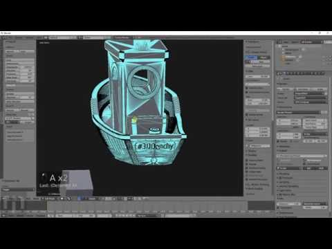
Blender 3D for 3D Printers / Sudo Null IT News
Correct position! But some problems can still be covered by polygonal modeling.
Gathered here the answers to the four most common and non-obvious problems.
Dimensions
When I tried to order 3D printing from a company for the first time about seven years ago, it was like this:
— Igor! You sent an empty file!
- No! Here's a screenshot, well!
One meter in the Blender is equal to one millimeter in the slicer, nothing has changed in these seven years.
Designing in meters is wonderfully inconvenient, so when exporting to STL/OBJ, set the Scale value to 1000:
Closed geometry The ability to create open geometry is both a scourge and a bonus of polygonal modeling.
In the modern world, slicers (not all) have learned how to work with this, but there may be surprises: want a hole? get a blank wall!
If you don't like surprises, you should use Blender's geometry analyzer.
In mesh edit mode, select vertex selection, and click Select → Select All By Trail → Non Manifold
To eliminate such trash as on the right ball, there is a Merge By Distance tool. Lives in Mesh → Clean Up → Merge By Distance.
In other cases, it is necessary to either give the wall thickness by extruding, or close up the hole, or is this geometry really necessary?
And now for the good news: in Blender 2.8 the 3D printing addon is built right into Blender, hooray! Geometry analysis just got easier. You just need to turn it on, and in the edit mode in the N-panel everything will be (and even the preliminary volume of the model!).
Flying geometry
As unclosed, only flying. So the slicer can still try to shove it into the G-code!
The annoyance is that if the volume of the walls was made by a modifier, these mesh pieces can no longer be found with the Non Manifold tool.
Select any polygon on the target mesh, and use the Ctrl+L hotkey: it will add all physically connected polygons to the selection. After that, invert the selection with the Ctrl+I hotkey and delete everything you don't need.
Normals
Roughly speaking, the polygon has a "face". When the polygon enters the slicer, the slicer looks at where the polygon has a “face”, tries to fill the wrong side with plastic, and at the same time checks for overhangs.
Accordingly, a cube with normals inside will be perceived clumsily. In fairness, in modern slicers this is no longer so important.
The solution is super-simple: turn on the display of normals:
Flip in the right direction: select the polygon with the normal turned inside out and press Alt+N. Hoba! and the slicer no longer panics about negative angles where they cannot exist.
General
Blender, indeed, is not developed as engineering software, and you should not try to solve furious tasks with it in the spirit of multicomponent kinematic systems.