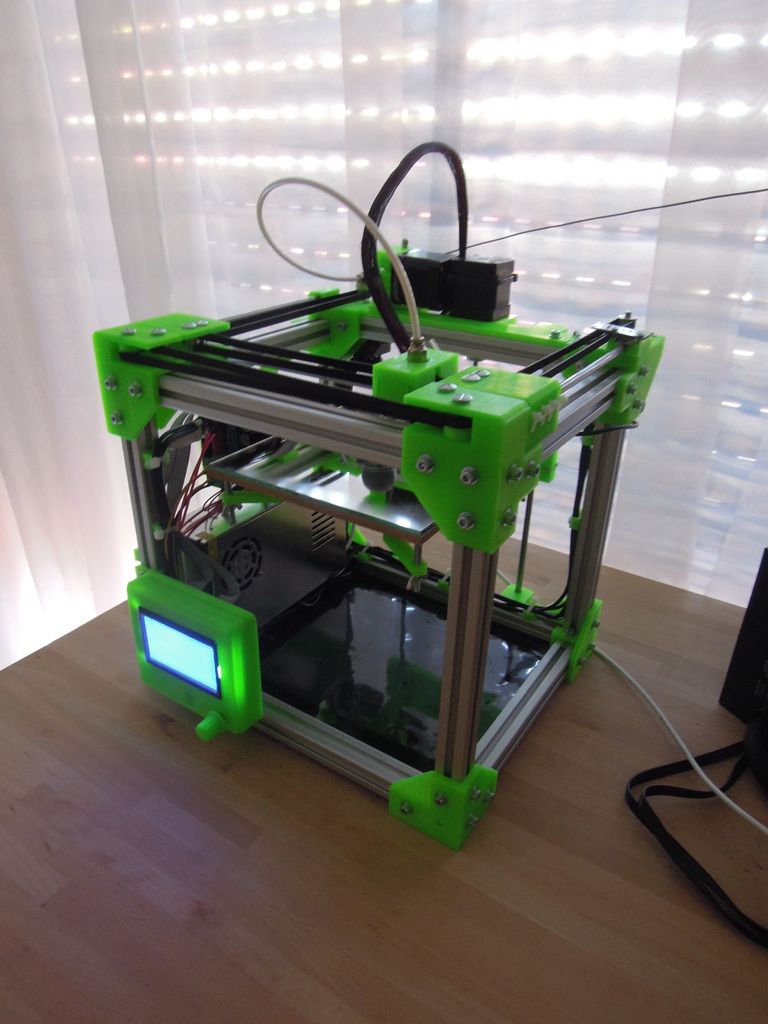
Pbf 3d printer
Powder Bed Fusion 3D Printing - PBF Machine
POWDER
BED
FUSION
Find the best compromise between productivity and parts quality with AddUp’s PBF technology
Why choose AddUp machines?
FormUp 350 machines are available in a variety of configurations: single or double laser, roller or scraper spreading device, standard or heating platform, reactive or non-reactive powders…
Would you like to evaluate the value of PBF technology for your project? Compare the performance of the FormUp machine against its competitors? Feel free to contact us. We have a multi-supplier workshop equipped with 23 machines. It will allow you to evaluate the capabilities of our machines and compare them with those of our competitors.
FORMUP®350
The FormUp 350 is a versatile machine with an open architecture, designed to help industrial companies produce the right parts at the right cost.
Discover the FormUp 350 >
Why choose AddUp machines?
FormUp 350 machines are available in a variety of configurations: single or double laser, roller or scraper spreading device, reactive or non-reactive powders…
Would you like to evaluate the value of PBF technology for your project? Compare the performance of the FormUp machine against its competitors? Feel free to contact us.
FORMUP®350
The FormUp 350 is a versatile machine with an open architecture, designed to help industrial companies produce the right parts at the right cost.
Discover the FormUp 350 >
What is PBF technology?
Powder Bed Fusion (PBF) technology is a metal additive manufacturing process that allows the production of high-precision parts with very high mechanical properties.
In a laser PBF machine, parts are made in successive horizontal layers. For each layer, metal powder is spread on a production platform, and a laser melts the areas that need to be solidified.
FormUp 350 machines are safe, efficient and scalable. They integrate more than ten years of experience of AddUp and Michelin in PBF technology.
Our PBF solutions : the best compromise between quality and productivity
FormUp machine offers a build volume of 350x350x350 mm, up to 4 lasers with 3D optical scanners ensuring a homogeneous laser beam on 100% of the platform surface.
Equiped with its Autonomous Powder Module, the FormUp is compatible with the finest powders on the market. Combined with our roller coating technology, it’s possible to produce very fine geometries, with very low angles, exceptional surface qualities, and very high mechanical properties and density.
Thus, you can design manufactured parts with very low numbers of supports that significantly increse productivity.
AddUp’s solution differs from competitors by being totally opened in terms of parameters. You can develop specific manufacturing recipe fo your project, achieving the best compromise between quality and productivity.
The safety of your operators at the heart of our concerns
Our production systems are designed to ensure the safety of your operators. Numerous means of protection are embedded in the machine: hermetic enclosure, nitrogen or argon inerting system, protection against electrostatic discharge, etc.
At the same time, AddUp’s recommendations for the safe use of machines are among the most restrictive on the market. Use of Personal Protection Equipment (PPE), cleaning procedures, ventilation and air filtration in the workshops, monitoring the exposure of operators… Every aspect of the process is taken into account in our safety procedures.
By following our recommendations, you guarantee a maximum level of protection for your operators and for all technicians working on the machines.
AddUp Manager : a complete and powerful software suite
Take advantage of all the possibilities of the FormUp 350 machine with AddUp Manager preparation software:
- Simple to use, it gives you access to all machine parameters and allows you to easily create experiment plans to adjust your manufacturing recipes.
- Powerful, it has an ultra-fast trajectory generation engine, to generate your manufacturing files faster.
- Open, it accepts many types of files for your parts models: STL, 3MF, STEP, Catia, NX, Pro/E, Inventor, Solidworks, and many others…
PBF 3D Printing - Laser Power Bed Fusion
FormUp® 350
Developed by manufacturers for manufacturers
The FormUp 350 machine is a solution for metal additive manufacturing using laser powder bed fusion (L-PBF). This modular and scalable machine offers a high level of productivity and allows the manufacture of high-quality parts while ensuring user safety.
Productivity of the FormUp 350 machine
100% platform coverage
The FormUp 350 machine has up to four 500 W lasers to meet your most demanding applications in terms of productivity. Each laser covers the entire platform surface, offering more freedom during build preparation.
40% faster powder spreading
The bidirectional coating system reduces non-productive time by 40% faster powder spreading cycles than monodirectional spreading.
Continuous powder supply
The Autonomous Powder Module, developed exclusively for the FormUp in partnership with AZO, provides all the functions of automatic powder management. It guarantees a constant supply of powder, without interrupting production, regardless of the quantities to be produced.
Average time between productions:
- 1 hour or less : Designed for mass production applications, the FormUp 350 machine limits the time between each production run
- 0 pollution during production: Low maintenance, using a long-life smoke treatment module (filter replacement interval of more than three years), and Cross Jet technology, which prevents soiling of the laser protection glass during manufacturing.
- 15 minutes for a complete inerting of the enclosure: Optimized production chamber sealing to reduce inerting times. 15 minutes are sufficient to reach an oxygen level of 500 ppm.
- 75% reduction in cooling time: A cooling system for the machine’s Z-axis lowers the temperature of the platform at the end of production, allowing parts to be unloaded more quickly (2 hours to cool down from 200 to 65°C, compared to 12.5 hours without active cooling).
- Fast and automated referencing: A probe-based platform referencing system. It only takes few seconds to adjust the positioning of the manufacturing trays and check their flatness, repeatedly and automatically.
1.27 million trajectories generated per second
AddUp Manager™ software offers a trajectory generation speed never seen on the market, up to 1.000 times faster than real production. AddUp NCore software embedded in the machine is capable of processing production files of more than 80 GB in one go.
A HIGH LEVEL OF QUALITY FOR METAL 3D PRINTED PARTS
The FormUp 350 machine will meet all your part quality requirements, in terms of mechanical properties, geometric properties (up to 0.1 mm dimensional accuracy), and material density (up to 99.99% Depending on the type and geometry of the parts and the material used).
160+ accessible parameters
All machine parameters are accessible. This allows you to develop application-specific manufacturing recipes and find the best balance between productivity and quality for each part. The platform can be heated up to 200°C, greatly reducing stress concentration and deformation risks.
Lasers accuracy to 35µm
All lasers are equipped with a 3-axis optical chain. This high-end technology guarantees both positioning accuracy (24-bit resolution) and laser beam quality. This accuracy is crucial for multi-laser applications on a single part.
10 µm** improvement in roughness with roller spreading
** Measurements carried out on TA6V particle size 5-25 vs 20-53
The FormUp 350 is the only machine on the market with an interchangeable coating device. Choose the powder spreading system best suited to your production: a scraper system for maximum productivity, or a roller system for improved surface finishing. This one enables support-free production of your cantileverd parts and 10 μm reduction in arithmetic roughness (Ra) regardless of the surface angle.
Ensure the highest level of quality for your parts with our different production monitoring and control solutions:
- AddUp Dashboards: For traceability and process analysis, visualize in real-time the 80 manufacturing parameters available on FormUp 350.
- Less than 1 second to analyze recoating: Real-time powder quality analysis technology checks the surface of the powder bed for defects and triggers a second round of the recoating system if necessary.
FormUp® 350 machine designed for operator safety
The architecture of the FormUp 350 allows you to use all types of metal powders, even the most reactive ones, such as titanium and aluminum alloys in fine powders.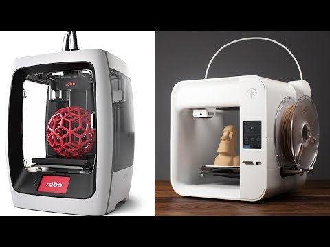
0 contact with the powder
Operators can work in complete safety with the Autonomous Powder Module, powder storage, machine feeding, and unfused powder recovering and sieving.
0 risk during waste disposal
Exposure to smokes and melting residues is also limited, due to the automatic passivation filter system, which allows for safe disposal of the waste.
Create a confined area in your workshop with ease
Is your workshop not suitable for the use of metal powders? AddUp offers the FlexCare solution, a fully integrated production system, that is easy to install and move. The FlexCare contains all the features of a metal additive manufacturing workshop: confined area with an airlock system, vacuum to prevent any powder leakage to the outside, air quality control, etc.
FormUp® 350 is a modular & scalable machine
2 configurations
The modular design of the FormUp 350 machines allows each manufacturer to configure the machine according to his needs. AddUp offers two predefined configurations to help you make your choice:
EFFICIENCY
The ideal configuration for manufacturers who are looking to get started in metal additive manufacturing with confidence, with a wide range of powders (fine or medium, reactive or non-reactive)
PRODUCTIVITY
The perfect answer for high productivity and industrialization, with four lasers and an Autonomous Powder Module.
25+ options to be integrated at any time
Opt for a controlled investment, with a machine designed to be scalable. Whatever the chosen configuration, you can add new modules, options or equipment to your machine at any time, thus delaying its obsolescence. AddUp is committed to ensuring that all future improvements offered on this range are compatible with your machine.
FormUp® 350 – PBF machine technical specifications
| Machine dimensions (without powder device) | L 2.55 x W 2.2 x H 2.32 m |
| Weight: 4 t | |
| Build volume | L 350 x W 350 x H 350* mm (~43 L) |
| Gas type | Argon or nitrogen with programmable control of oxygen level (≥ 500 ppm) |
| Laminar flow | Adjustable from 0.5 to 3 m/s |
| Laser glasses protection | Cross Jet system |
| Optical chain | Up to 4 x 500W Ytterbium continuous fiber lasers (1070 nm) |
| Spot diameter: 70 µm | |
| 100% platform coverage by each LASER | |
| 3D scanners: 2 axis for X/Y displacements + 1 axis for focal adjustement Max speed of 10m/s 35 µm accuracy | |
| Visualization | Supervision camera Camera for HD pictures (option) |
| Powder recoating device | Bidirectional Scraper (carbon brushes or silicon) or roller |
| Layer thickness: 20 to 120 µm | |
| Part properties | Precision: up to 0. 1 mm** 1 mm**Density: up to 99.99%** |
| Heated platform | Up to 200°C Cooling system to improve temperature drop time after production |
| Standard Powder Module | For non-reactive and middle size powders |
| Autonomous Powder Module | For all types of powder *** |
| Inerted condition | |
| Sieving device integrated | |
| Powder recovery during production | |
| Glove box (option) | |
| Inerted vacuum integrated | |
| Fume and fusion residus management | Filtration device with automatic unclogging sytem |
| Calcium carbonate residus passivation | |
| Filters lifetime > 3 years | |
| Cooling device | Air / water |
| Interoperability | OPC-UA / MQTT (option) |
| CAM solutions | AddUp Manager or NTwin |
| Simulation software | Distorsion Simulation AddOn (option) |
| Monitoring | AddUp Dashboards (option) |
| Remote Maintenance | AddUp Remote Control |
* Up to 370 mm using a less thick platform
**depending on part geometry, material and melting parameters used
*** with AddUp validation
Data for information only, subject to change.
Services to help you integrate your PBF machine
Our workshop to support your projects
The AddUp group operates its own manufacturing workshops, with one of the largest capacities in Europe: over 40 metal additive manufacturing machines. We can offer you different solutions to support your production: assistance in increasing your production rate, additional capacity, or a “twin” machine in our workshops to help you continue your operations.
1-year warranty
FormUp 350 machines are guaranteed for 1 year, with maintenance contracts tailored to your needs:
- spare parts available within 48 hours,
- web portal accessible 24/7,
- hotline service available 5 days a week from 8 am to 6 pm,
- remote connection to the machine,
- Preventive Maintenance contract
Ready for industry 4.0
Easily connect your machines to your shop floor software with OPC-UA and MQTT gateways that promote interoperability.
Simplify your digital chain, from design to finished part, with a direct import of your CAD files. More than 10 formats are supported: CATIA, SolidWorks, Creo, NX, etc.
9 training modules, from beginner to expert
Finally, AddUp offers a wide range of training and support services to assist you in integrating the machine, exploiting all its capacities, and developing your expertise in the process to gain autonomy.
FormUp® 350 – PBF machine technical specifications
By design, FormUp® machines are compatible with all types of materials. Recipes and adjustments are already available for the following materials:
If your material is not yet listed, please contact us so that we can estimate the timeframe for the machine adjustments and tests.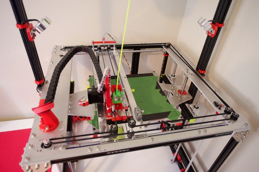
Wedج المحاولة مرة خرى للصص اليا# أو الال لـship imesز المς للمزيد ← المومات
66
Omlouváme se, nemůžeme najít stránku, kterou hledate. Zkuste se vrátit zpátky na předchozí stránku, nebo se podívejte do našeho Centra nápovědy pro více informací
Přejít do informačního kanálu
Vi kan desværre ikke finde den side, du leder efter. Gå tilbage til den forrige side, eller besøg Hjælp for at få flere oplysninger
Gå til dit feed
Die gewünschte Seite konnte leider nicht gefunden werden. Versuchen Sie, zur vorherigen Seite zurückzukehren, or besuchen Sie unseren Hilfebereich, um mehr zu erfahren.
 Zu Ihrem Feed
Uh oh, we can't seem to find the page you're looking for. Try going back to the previous page or see our Help Center for more information
Go to your feed
Vaya, parece que no podemos encontrar la pagina que buscas. Intenta volver a la página anterior o visita nuestro Centro de ayuda para más información.
Ir a tu feed
Nous ne trouvons pas la page que vous recherchez. Essayez de retourner à la page précédente ou consultez notre assistance clientèle pour plus d'informations
Ouvrez votre fil
Maaf, sepertinya kami tidak dapat menemukan halaman yang Anda cari. Coba kembali ke halaman sebelumnya atau lihat Pusat Bantuan kami untuk informasi lebih lanjut
Buka feed Anda
Non abbiamo trovato la pagina che stai cercando. Prova a tornare alla pagina precedente o visita il nostro Centro assistenza per saperne di più.
 Vai al tuo feed
申し訳 あり ませ ん。 探し の ページ が ませ ん。 前 の ページ 戻る か 、 ヘルプセンター で を ご 確認 ください
원하시는 이전 페이지로 돌아가거나 고객센터에서 자세히 알아보세요.
홈으로 가기
Harap maaf, kami tidak dapat menemui laman yang ingin anda cari. Cuba kembali ke laman sebelumnya atau lihat Pusat Bantuan kami untuk maklumat lanjut
Pergi ke suapan
De pagina waar u naar op zoek bent, kan niet worden gevonden. Probeer terug te gaan naar de vorige pagina of bezoek het Help Center voor meer informatie
Ga naar uw feed
Vi finner ikke siden du leter etter. Gå tilbake til forrige side eller besøk vår brukerstøtte for mer informasjon
Gåtil din feed
Nie możemy znaleźć strony, której szukasz. Spróbuj wrócić do poprzedniej strony lub nasze Centrum pomocy, aby uzyskać więcej informacji
Przejdź do swojego kanalu
A página que você está procurando não foi encontrada.
 Volte para a página anterior ou visite nossa Central de Ajuda para mais informações Voltar para seu feed
Ne pare rău, nu găsim pagina pe care o căutatţi. Reveniţi la pagina anterioară sau consultaţi Centrul nostru de asistenţă pentru mai multe informaţii
Accesati fluxul dvs.
The page you are looking for cannot be found. Please return to the previous page or visit our help center page for more information.
Go to tape
Sidan du letar efter hittades inte. Gå tillbaka till föregående sida eller besök vårt Hjälpcenter för mer information
Gå till ditt nyhetsflöde
ขอ อภัย ดู เหมือน เรา พบ หน้าที่ คุณ กำลัง หา อยู่ ลอง กลับ ไป ที่ เพจ ก่อน หรือ ดู ศูนย์ ความ ของ เรา สำหรับ เพิ่มเติม
6
Naku, mukhang hindi namin mahanap ang pahina na hinahanap mo. Subukang bumalik sa nakaraang pahina o tingnan ang aming Help Center para sa higit pang impormasyon
Pumunta sa iyong feed
Aradığınız sayfa bulunamadı.
 Önceki sayfaya geri dönün veya daha fazla bilgi için Yardım Merkezimizi görüntüleyin Haber akışınıza gidin
前往首頁動態
Additive technologies from SBI
1. Additive technologies, overview
add). Installations that use these technologies are also called 3D printers.
These technologies are the most promising technologies of the present and future. Layer-by-layer building up and synthesis of an object occurs with the help of 3D computer technologies and contributes to the production of many useful things for everyday life, human health and safety, for example, additive technologies in aircraft manufacturing help to create more highly economical and lighter air transport, while its aerodynamic properties are fully preserved. In 2009, this ASTM (American Society for Testing and Materials) process was classified as an AM technology (Table 1).
Table 1: Classification of AM-processes
The main technically feasible methods of manufacturing metal products are Powder Bed Fusion (PBF ) and Directed Energy Deposition ( DED 901).
While the PBF process can produce small and complex geometries, the DED build-up processes can produce large-sized parts with high productivity and speed.
Powder or wire can be used as a material for DED build-up process, for metal melting it is used as a light arc between the electrode and the workpiece, a laser beam or an electron beam electron beam.
A variation of the DED wire-fed build-up process is classified as Wire and Arc Additive Manufacturing or (WAAM) for short. This designation was introduced by Cranfield University and describes which wire and which energy source is used when building products using an electric arc.
At the disposal of the AM processes, various ways of building up products are offered. However, this does not mean that every possible solution is economical and efficient.
Products manufactured according to AM extension technology can be classified according to the degree of their complexity in the following graph (Fig. 1).
1).
Large parts with a relatively simple design are made using the DED build-up process, small and complex products using the PBF build-up process
Figure 1. AM process and its scope
2. Why AM?
Today's requirements for the competitiveness of the company and the environmental friendliness of production are becoming more complex every day. Additive manufacturing provides a solution that meets both of these requirements. The so-called buy-to-fly-ratio (BTFR) indicates the ratio of raw materials to the finished component:
Where at the top of the fraction is the mass of the workpiece, and at the bottom is the mass of the finished product.
Some manufacturing methods, such as turning and milling, have a BTFR value of 5-50 or even higher, depending on the structural complexity of the part, i.e. a lot of material goes into chips (Figure 2).
Additive manufacturing can significantly reduce this ratio - depending on the degree of post-processing. A lower BTFR not only saves raw material costs, but also reduces the cost and time required to rework products.
Figure 2 Chips are the main material in the normal production of products
Another advantage offered by AM, is the rapid production of the required products. Especially in the case of expensive and rather rarely used materials in production, very long production times are a problem, AM solves these issues.
Using additive manufacturing, a product can be quickly produced on site and using materials readily available on the market.
3. PWD process: Plasma Wire Deposition
PWD process uses a wire-fed plasma arc to build up products and is classified Directed Energy Deposition DED and WAAM . The basis for this method is a plasma torch that produces a plasma arc, which transfers the wire introduced into it onto a prefabricated product substrate. When the metal is melted, one pass is created on the product, with a given number of passes, a product ready for processing is created.
Figure 3 shows a diagram of the PWD process with the introduction of the wire into the plasma arc and the formation of passes on the product.
Figure 3. PWD-process diagram
Plasma arc (PTA ) depending on the current source used, operates in two modes: (-) is supplied to the tungsten electrode of the plasma torch, and (+) to the product.
Straight polarity mode DCEN is used to build up various metals: steel, titanium, nickel base alloys.
AC mode - for building aluminium.
The ability to change the operating mode allows you to select the correct production mode. In addition, DC modes can be pulsed for better control of heat input. The pulse frequency can be set from 1 Hz to 2000 Hz.
PTA Advantage is the ability to start a plasma arc without adding wire.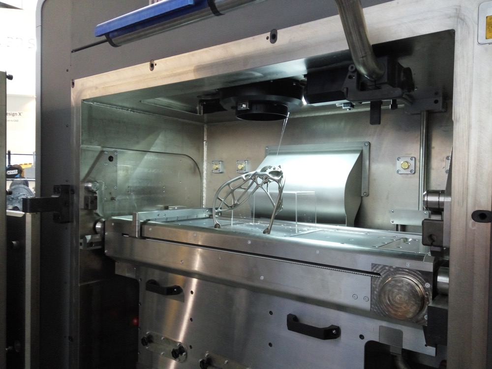 This allows you to create process parameters such as preheating the base before welding and the workpiece itself.
Unlike other DED power sources, the plasma torch generates a high pressure plasma that presses the weld pool in the opposite direction of the torch travel. This property allows you to accurately complete the surfacing of the layer in the manufacture of a non-circular part of the product.
Figure 2 :
layer pattern Figure 2 shows the layer pattern. Because the plasma "presses" the weld pool in the opposite direction (1), the end edge is not straight (2). When welding in the opposite direction, the weld pool is pressed against the end edge (3) and a smooth edge is formed.
PWD is not prone to forming a layer of "humps" on the surface.
For higher deposition rates, welding with hot wire . Heating of the welding wire is achieved by creating a chain between the workpiece and the wire. When the wire touches the workpiece, it is heated by the resistance and reduces the energy consumption of the plasma to melt the wire. In this way, higher wire feed speeds are possible and a higher deposition rate is achieved.
Figure 3 : Higher deposition rates with hot wire
Materials and welding options
Since the AT -system works with PTA, the materials used - the raw material (in the form of wire) and the base - must be conductive. All materials that can be welded with PTA can be produced with our AT system. Table 2 shows all preferred combinations of PTA modes with known materials.
Table 2 : Possible Weld Modes and Material Combinations
The AT system can use a multiple wire feeder (MWF), which means it feeds multiple wires into the PTA. MWF provides lower wire feed speeds, which makes the printing process even more stable.
Figure 4 : Wire feeder and plasma torch AT system
Deposition rate
One of the main advantages of PWD is its high deposition rate compared to other AT processes.
During our testing, we achieved deposition rates of 4-10 kg/h depending on the materials used and the set of welding parameters used. However, the potential limit is much higher and we are constantly finding new parameters to achieve higher deposition rates.
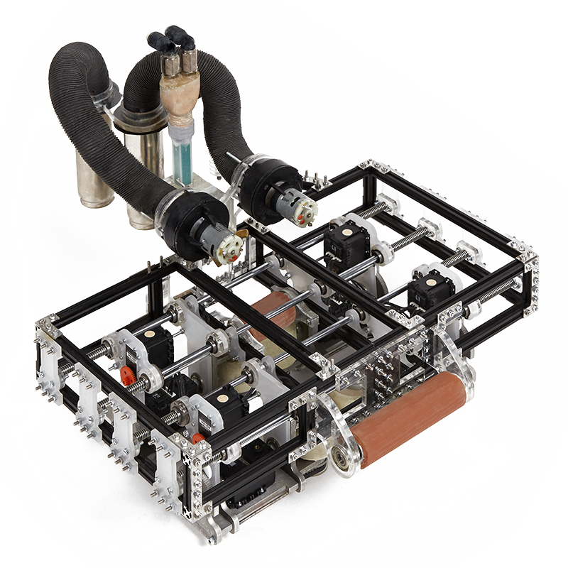
4. Diagram of 3D printer
The 3D printer (Figure 5) consists of a 6 axis CNC setup.
- 4 axes for moving the plasma torch (X, Y, Z axes, rotation along its C axis)
- 2 axes of the turntable (A, B)
fig 5 the axial design of the plant allows the production of cylindrical, spherical, conical and general three-dimensional objects (fig. 6)
The maximum size of the products is 800x600 mm with a maximum weight of 500 kg. A 2400x1200 mm clamping table can be installed instead of the tilt-rotator. This allows you to implement products with a size of 2000x600x600 mm, weighing up to 2000 kg.
Since 3D build-up places the highest demands on the product being produced, a protective gas atmosphere must be maintained around it throughout the entire printing process.
The unit is designed to keep the gas filling time as fast as possible and in a sufficiently small volume, which in turn shortens the purge time and saves inert gas.
fig 6 example of grown products
The entire process of growing a product is controlled and recorded by a video camera system and is linked to the parameters of the movement and the growing process recorded in the memory (for example, plasma current, plasma voltage, gas flow, etc.) This greatly simplifies, for example, the subsequent evaluation and optimization of the process.
Another condition for ensuring the quality of build-up is the control of the product geometry, where after each layer the object is scanned and its nominal geometry is compared with the actual geometry. By controlling the plasma parameters, defects such as pore formation can be detected and eliminated.
Figure 7 shows a 3D scan of the product showing the substrate and material structure (red coloration).
fig 7 3D scan product
In order to ensure, in an inert gas filled installation, a quick change of the substrate and wear consumables and spare parts, “hand gloves” are built into the 3D printer.
The whole process of extension movements is controlled by G-code and the movements that occur can be monitored during the movements via the human-machine interface.
fig 8 Axes on the 3D printer
Figure 9 shows the basic design of the 3D printer, the installation consists of a working area and a control cabinet. Thanks to its compact design (3200x2100x3200) and a total weight of up to 5000 kg, the unit can be placed in a container.
The unit's control cabinet consists of a controller cabinet, an inverter cabinet and a cooling circuit cabinet.
Fig. 9 Plant cabinet diagram
The cooling circuits of the units are connected to an external cooling source, which can be implemented either with a refrigeration unit on site or with a cooling network.
Side-mounted control panel for entering motion and plasma arc parameters when building up a work piece.
The frame of the unit is made of stainless steel, to which are attached the axes (X, Y, Z), rotary table, plasma torch and wire feeder.
The relatively small volume of the inert gas plant, approx. 10 m³, reduces the purge time as well as the inert gas consumption.
The software called Plasma Control Software (PCS) is developed by our programmers and can be used according to our customers' needs.
Materials and Jobs Used
AM uses Dual Wire Feeder (DWF), optional Multiwire Feeder (MWF). They provide a lower wire feed speed compared to single wire feed while maintaining the same productivity. In addition, DWF and MWF provide a more stable process and allow you to organize workpiece alloying. Doping can be local (zoning) or global. The following figure (10) shows alloying by adding two different types of wire.