Linuxcnc 3d printer setup
From 3D Printing to Machining Metal Parts
This article walks through the conversion of a g0704 mini mill to a CNC machine using LinuxCNC. I avoid the cost of a ballscrew conversion and instead use software backlash compensation with the stock ballscrews and am still able to achieve great results:
Way back in 2016, I got my first 3D printer and my eyes were open to the world of rapid manufacturing. The accessibility of information and tools for 3D printing are outstanding, in no small part to the founder of the open source 3D printer RepRap project, Dr. Adrian Bowyer.
After 4 years of learning to build 3D printers, designing new CAD models, and printing plastic parts, I decided it was time to make parts out of metal. Rapid manufacturing in metal is a fascinating topic, but is not nearly as accessible in terms of costs and publicly available information as plastic 3D printing. Therefore, I opted for a CNC milling machine.
Choosing a Machine
I spent a long time trying to figure out the best machine to buy. I looked at options from Tormach, littlemachineshop, Harbor Freight, and Sieg (the actual manufacturer of most mini-mills). In the end, the Tormach was too expensive, the benefit of a little machine shop over the Harbor Freight version was not worth it to me. I looked into getting a Sieg KX1-MACH, and would have chosen this, but importing it in the middle of the pandemic did not work out. If you're someone who does not want to build their own CNC, the Sieg KX1 seems like the best option. I really wanted an iKX1S-SIEG which has an option for a toolchanger, a faster spindle, and an enclosure, but the exclusive importer of these is Intelitek and they wouldn't sell me one. The folks at Sieg are very accessible, so if you are interested in this route, just email them directly.
In the end, I found and purchased a used Grizzly g0704 mill and South Bend lathe.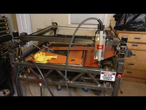 While the g0704 is just a re-branded Sieg machine, and way over-priced if purchased new, great deals can be found on a used machines.
They were a bit dirty when I picked them up.
They cleaned up nicely and I mounted them on a table made out of 8020 aluminum extrusion. Having both machines on the same sturdy table was very useful as their collective mass makes them more stable than if they were mounted somewhere separately. Adding mass to your machine, by a mounting configuration such as this or some other way, is a simple way to improve the precision of the machine. More mass reduces the potential for anything to move or vibrate during usage. A sturdy mounting of some sort is highly recommended.
Take note, the axes configuration on this machine, once converted to a CNC will be as described in the LinuxCNC User Guide, here are the axes are configured:
While this article is not about the lathe, it was very useful in making couplers for the mill, as I describe below.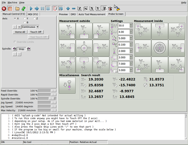
Thanks
Thanks to everyone I talked to along the way. Notably, Chris at littlemachineshop.com, was very helpful, all the folks I talked to at siegind.com and Chris Li at Leadshine America who sold me the electronics as discussed below.
William McKnight at Carbide Depot was kind enough to supply a couple 1/4" carbide end mills, which I've been using to cut all types of material. They're so much more resilient than my high speed steel (HSS) tooling. You can see the end mill in action here. I'm cutting some steel inserts:
Hardware CNC Conversion
There are quite a few options to convert the manual g0704 to a CNC. The first choice is if one should use ballscrews or not. I decided to convert the machine without changing to ballscrews and use software backlash compensation, which turned out great.
Aside from being able to achieve great results without the cost of ballscrews, the main benefit of doing a leadscrew only (no ballscrew) conversion is that there is very little modification required to retrofit the g0704. The way I achieved this was by designing motor mounts that fit onto the existing mounts and couplers that fit over the nuts that hold the leadscrews on the x-axis and the y-axis, so permanent modification of the existing hardware for the leadscrew is required.
The two main things you'll need to make are the motor mounts and motor shaft couplers.
Leadscrew Motor Mounts
For the motor mounts, I started with the x and y axis:
I designed and 3D printed the y-axis mount, you can download the y-axis-mount.stl on thingiverse.
I cut the x-axis mount plate on the G0704 from 1/2" Aluminum stock by hand. The standoffs were cut to 2.10" (53.29mm), then drilled and tapped for M4 bolts.
Here is the x-axis drawing, if you would like to make your own:
I cut the z-axis last using the installed x-axis and y-axis cnc components. If you want to CNC the z-axis plate, the STL can be found on thingiverse. The reason this cannot be milled by hand is the center must be a circle. Standoffs were created the same way as the x-axis, but cut to 2.52" (64mm).
Here is the z-axis drawing:
Leadscrew Couplers
The x-axis coupler and y-axis coupler are the same. I designed them to replace the manual handle without modifying the other hardware on the axis, so the nut that would normally hold the handle in place, fits inside the coupler. Here is the original design:
In the final version, I decided to use 3mm rod to pin the couplers together to drive the shaft from the motor, instead of the 3x M3 set screws originally planned:
I made the couplers on the lathe, then drilled out the holes for the M3 pins on the mill.
The z-axis coupler is a simple fixed-shaft (solid) coupler:
Another Option: Ballscrews
The other option is to convert the lead screws to ballscrews. The drawings for the ballscrews are below, if you decide to go this route. You'll also need to actually modify the base of your g0704 as described in various places on the web, such as here: https://www. youtube.com/watch?v=wFzgrUe63xQ.
I have not checked these drawings myself, as I decided to use software backlash compensation, explained further below, instead of ballscrews, which made the conversion simpler.
Another option is to buy a kit such as: https://www.automationtechnologiesinc.com/products-page/g0704-bf20-pm25mv-x2-x3-kit/g0704-with-duf-ballscrew or https://www.heavymetalcnc.com/g0704/. However, these kits cost about $700, which is way more than I wanted to spend.
So far, I've been able to get great performance without ballscrews, as you can see from the video at the top of the page. The one downside is the head is not very heavy, so I have to take z-axis plunges quite slow to avoid the head riding up on the z-axis backlash. If I were to add a ballscrew, it would be for the z-axis, but don't see the need at this point and plan on just taking relatively slow plunge cuts.
Tooling
-
Collet Set for holding endmills. I got a full collet set, with my used mill purchase, but if you're just starting out, it may be better to pick a single size and just get the one or two collets you need.
 I use my 3/8" collet almost exclusively. If you're buying endmills, just buy them in the size that fits your collet, the shank size must match the collet, but the cutter size does not have to be the same as the collet.
 -
Drill Chuck I prefer a keyless chuck. The main consideration here is to get one that is not too tall to avoid having to bring the head way up before changing it! I actually bought a bit taller one that was cheaper, but I should have gotten the shorter one.
-
4" Precision Vise for work holding. A 4" vise is about the biggest you'll want and even this is a little big. I had to clamp mine down a bit creatively, since it does not fit well using the normal bolt cutouts -- it's a little too close to the back of the mill. Notice how I'm holding the vise in the photo below. Holding it this way works great.
Cutters
-
Endmills The best endmills to purchase will depend on the material you intend to work with. I suggest the material you start with aluminum or brass, which tend to be easier to work with "free machining" materials.
 For these, a set of two-flute High Speed Steel (HSS) cutters will do the trick. Remember to buy a set with a shank size matching your collet.
 -
Center Drills are necessary for starting (drilled) holes in the correct locations.
-
Drills are for drilling holes. You can use any drills, but a large set of HSS bits will ensure you have the right size for the job.
Measurement
Electronics
For CNC control, I'm using an old computer with a parallel port and a SainSmart 5 Axis CNC Breakout Board. SainSmart has a nice manual. Stepper online has their own version of the same manual as well. However, all of these manuals cover Mach4 and not LinuxCNC. This guide walks through the LinuxCNC setup in detail below.
Instead of buying from a Aliexpress or Amazon seller, I decided to get my electronics straight from a distributor. I think this is important so one gets a product that meets the specifications described in the manual. The distributor with the best product quality and price combination I found was Leadshine America. I'm using authentic Leadshine 4A stepper motors with DM556E drivers. I also bought a 48v, 10.5A power supply from Leadshine as well.
Here is the full electronics part list:
3x Stepper Motors: 57CM31-4A-I9 @ $49 each = $147
3x Stepper Drivers: DM556E @ $40 each = $120
1x 48V, 10.5A switching power supply: RPS4810 @ $55
Shipping was just over $20 and was quite fast, arrived from the west coast to my home on the east coast in only few days.
If you would like to order the same electronics I used, contact Chris Li at Leadshine America. Let him know you found him via this article. He did mention the power supply option, RPS4810, may be updated soon, so that might have a new model number if you order, but the rest should be the same.
I initially wanted larger motors, but Chris thought longer (more amperage) stepper motors would be too loud. It turns out these steppers work great and are nice and quiet for my use. Even running at full amperage, they stay nice and cool maxing out around 120 degrees Fahrenheit.
I also wanted steppers with a shaft that protrudes so I could attach a handle for manual motion. It turns out this is not necessary at all once the CNC is setup, and could actually cause a problem if manually moved, changing the zero point, so I am glad I got the version without the extended shaft.
I considered getting the more expensive DM556S stepper drivers, but am glad I went with the less expensive DM556E option that I chose, since this is more than sufficient for my use.
Wiring
First, some terminology.
The controller is the card that plugs into your parallel port on the computer.
The drivers connects to the controller and a stepper motor. There is one driver per stepper.
Controller to PC
You can use a parallel port cable if you have one. Since I don't a parallel port cable, I plugged the controller straight into the back of the PC. Since the USB cable no longer fits, I re-wired the cable by soldering it to the other side of the PCB. We only need to wire the USB cable's
 +5v and GND lines.
The board also needs 12v. For this, I tapped the yellow +12v line and black ground line from the computer power supply to the CD-ROM drive. I wired these to the parallel port adapter board.
Controller to driver connections
All the + control lines go to a +5v line
The DIR and PUL lines go to the same line on the correct axis. Note that on my controller, the PUL line is labeled CLK, which is fine, it does the same thing.
The ENA pin on the drivers all go to the same enable pin on the controller
Driver to motor
Using our wiring diagram for the motor, we see the correct connection by wire color
You'll also need to plug in your high-voltage supply
Driver Configuration
Here is a link to the full pdf manual for the Leadshine DM556E drivers.
The dip switches map to:
I set the RMS current to 3. 5A for the X and Y axis. The RMS current for the Z axis needed to be a little higher, so I set it to 4.0A:
I left the micro stepping setting to the default setting of 2: OFF, ON, ON, ON
Software: LinuxCNC
There are basically 2 options for controlling a CNC milling machine with a computer: LinuxCNC or Mach4/4. From everything I read, LinuxCNC is much more powerful and flexible. Plus it's free and open source, which is always a plus. The only constraint is that you'll need a computer with a parallel port or you'll need to buy an extension board. Cards from Mesa such as the 7I92M Anything I/O Ethernet card are a popular way to add a parallel port to new machine. If you choose to use Mach4 or Mach5, you can plugin the controller to any USB port. I'm using a computer with a built-in parallel port.
Installing Linux CNC
Look for the latest version available on http://www.linuxcnc.org/iso/linuxcnc-2.8.0-buster.iso
I'll be using what is currently the latest LinuxCNC 2. 8.0, Debian 10 ISO, which includes the realtime PREEMPT-RT kernel patch.
Burn the ISO to a USB stick. I used balenaEtcher on my Mac.
Install the Debian 10 distro from the USB stick. Detailed instructions can be found here: http://linuxcnc.org/docs/2.8/html/getting-started/getting-linuxcnc.html
Configuring and testing the parallel port
First, if you're using a computer with an onboard parallel port, enter the bios and make sure SPP mode is enabled.
Once you've got it connected and configured, run a test to make sure the parallel port is working by launching LinuxCNC and choosing the appropriate test port:
Use a multimeter in DC mode. Put the leads on the P2 pin and 5v pin. It should read ~5 volts. Click the Pin 02 button and the voltage should drop to 0. If this works, you're ready to move on.
Configuring the machine
Once you've got the OS installed, launch stepconf from a terminal or the Applications menu bar.
Create a new configuration, I'm using metric units, as most drawings I do are in metric.
Set the machine name, mine is set to g0704. Choose "Other" for the Driver type and use the Driver Timing Settings are from the table here. Search for DM556 and you'll find:
Step Time: 2500 Step Space: 2500 Direction Hold: 10000 Direciton Setup: 5000 Steps on: Rising Edge
Run the HAL Latency Test. Use the computer for a bit and then record the Max Jitter (ns) value.
Enter the max value and continue to the next screen.
For the parallel port config, set pin 14 to Amplifier Enable, matching the label of the pin on the board.
Recall we left the drivers set to the default microstepping value of 2 (switch 5-8: off,on,on,on), so leave this to 2 in the setup
For the X and Y Axis config, we'll compute the leadscrew pitch which is indicated on the g0704 handles as 0.1" per revolution. Converting this to mm/rev we get: 2.. I'm not sure how aggressive the default Maximum Velocity and Acceleration are at 25 and 750 respectively, so I'll turn these down to 10 until I get everything dialed in. 54 mm/rev
If you want to update the .ini configuration file later, the formula to convert this 2.54 mm/rev into "steps per user unit" used for the SCALE variable is described here http://linuxcnc.org/docs/html/config/stepper-quickstart.html#_mechanical_information and is as follows for my g0704 and motors:
STEPS_REV = 200 steps per revolution (equivalent to 360/1.8) MICROSTEPS = 2 microsteps per step LEADSCREW_PITCH = 2.54 mm per turn
Then scale is:
SCALE = STEPS_REV * MICROSTEPS * LEADSCREW_PITCH = 200 * 2 * (1/2.54) = 157.480314961
For the Z-Axis, the handle indicates 0.166" per revolution or 4.2164 mm/rev, so our Z-Axis scale is:
SCALE = STEPS_REV * MICROSTEPS * LEADSCREW_PITCH = 200 * 2 * (1/4.2164) = 94.867659615
Backlash Compensation
After ensuring your scale is correct, measure the backlash using a dial indicator.
Add this to the g0704.ini file under each axis. Also increase the axis joint's MAX_ACCEL value by 2x
Probing
I built a touch probe and touch plate for easier and more reliable setup.
Usage
I have setup my machine to be manually homed above the touchplate. To avoid a crash, be sure to home it such that the longest tool can travel down 50mm before contacting the touchplate! The tool will automatically move 50mm down before probing. This settings is further described below, but change the following parameter to change this behavior.
[TOOLSENSOR] ... # Absolute Z start search coordinates Z = -50 ...
With the probe in place and the machine homed above the touchplate, use the two remap M6 buttons on the probe screen to first probe the touchplate then probe the workpiece height.
With this done, probe the workpiece to set the G54 offsets and begin machining.
Even without limit switches, the machine can easily be kept homed between power cycles by homing the machine before turning off the machine and when the machine is re-powered on, simply set the home to the current position before moving the machine.
Probe Hardware
I built two probes, a tool setter and a touch probe. They are both normally closed and wired in parallel, so if either one triggers, the pin will go low.
Tool Setter
I don't have plans for the touch place, but it's basically just a microswitch bolted into a turned piece of aluminum round stock. There is a hole in the bottom so it can be bolted onto the table. I also placed a lightweight spring inside the mechanism to encourage the touch plate to move back up when not under pressure.
The touch plate diameter on the top is just under 20mm.
Touch Probe
I designed a mostly 3D printed touch probe. The design files and detailed build instructions are available on thingiverse.
It uses 6x 8mm bearings (actually 7.5mm diameter) in conjunction with 3x 4mm steel rods to create an exact-constraint mechanism. When the mechanism in capture, the circuit is complete. When the probe is moved slightly in any direction (including up), continuity is broken and the switch triggers.
The small wires are held in place under the pressure of the bearing. Bearings are attached by a small m3 bolt into a drilled and tapped hole in the bearing.
The rods are press fit into the probe-tip holder in the middle.
Capture is encouraged using a spring.
Any size shaft and probe tip can be used. I used a 1/2" piece of steel rod I had laying around for the shaft and a small brass rod along with another ball bearing for the tip. This works well, but with such a large tip, probing any surface with less than 4mm height is not possible, so I will probably change this to use a small ruby tip in the near future.
The top of the probe is connected with 3x m3 bolts.
Wiring
Both probes are wired in parallel, as shown below.
There is also a connector for the touch probe, so it can be removed if necessary, while maintaining continuity for the tool setter.
Probing Setup
Configure the HAL, one wire of my probe is plugged into pin 15 and the other wire to the nearby ground.
Configure the HAL as follows:
net probe-in <= parport.0.pin-15-in net probe-in => motion.probe-input
Install probe screen v2
Comment out the bottom of the hal file, replacing them with the single line config for probe screen:
Comment out:
#loadusr -W hal_manualtoolchange #net tool-change iocontrol.0.tool-change => hal_manualtoolchange.change #net tool-changed iocontrol.0.tool-changed <= hal_manualtoolchange.changed #net tool-number iocontrol.0.tool-prep-number => hal_manualtoolchange.number #net tool-prepare-loopback iocontrol.0.tool-prepare => iocontrol.0.tool-prepared
Add:
net tool-prep-loop iocontrol.0.tool-prepare => iocontrol.0.tool-prepared
Download and unzip:
curl -L https://github.com/kiall/probe_screen_v2/archive/linuxcnc-2.8.zip -o linuxcnc-2.8.zip sudo apt install -y unzip unzip linuxcnc-2.8.zip cd probe_screen_v2-linuxcnc-2.8/
Copy the configs into your machine configuration directory, my config directory is ~/Desktop/g0704
cp -r python ~/Desktop/g0704/ cp -r macros ~/Desktop/g0704/ cp -r probe_icons ~/Desktop/g0704/
Install the plugin by adding the following in the [DISPLAY] section of the . config file: ini
ini
EMBED_TAB_NAME=Probe Screen EMBED_TAB_LOCATION = ntb_user_tabs EMBED_TAB_COMMAND = gladevcp -x {XID} -u python/probe_screen.py probe_icons/probe_screen.glade Configure the plugin by adding this to the bottom of the .ini file and modifying as necessary. Take care to merge any sections that already exist, such as RS274NGC:
[TOOLSENSOR] # Absolute coordinates of the toolsetter pad X = 0.001 Y = 0.001 # Absolute Z start search coordinates Z = -50 # Maximum search distance and direction (sign) MAXPROBE = -170 # Speed of movements during working in Probe Screen RAPID_SPEED = 240 # Diameter of toolsetter pad TS_DIAMETER = 19 # The speed of the reverse rotation of the spindle when measuring the tool diameter REV_ROTATION_SPEED = 300 [CHANGE_POSITION] # Abs coordinates tool change point X = -20 Y = -20 Z = -10 [RS274NGC] PARAMETER_FILE = linuxcnc.var RETAIN_G43 = 0 INI_VARS = 1 HAL_PIN_VARS = 1 SUBROUTINE_PATH = macros REMAP=M6 modalgroup=6 prolog=change_prolog ngc=manual_change epilog=change_epilog [PYTHON] PATH_PREPEND = ./python TOPLEVEL = python/toplevel.py
Note: that with this configuration the toolhead or probe will drop to Z = -50 (in absolute coordinates) before probing up to -170mm more. Make sure your tool is at least 50mm above the toolsetter or decrease this value!
More user documentation for probe screen v2 can be found here: https://vers.by/en/blog/useful-articles/probe-screen
Fusion360
I use the Fusion360 Manufacturing tools for my CNC toolpath planning and code generation. The included LinuxCNC post processor works great:
LinuxCNC | Hackaday
September 20, 2022 by Dan Maloney
While most of us live in a world where the once ubiquitous Raspberry Pi is now as rare as hens’ teeth, there’s a magical place where they’ve got so many Pis that they needed to build a robotic dispenser to pick Pi orders. And to add insult to injury, they even built this magical machine using a Raspberry Pi. The horror.
This magical place? Australia, of course. There’s no date posted on the Pi Australia article linked above, but it does mention that there’s a Pi 4 Model B running the show, so that makes it at least recent-ish. Stock is stored in an array of tilted bins that a shuttle mechanism accesses via an X-Y gantry. The shuttle docks in front of a bin and uses a stepper-controlled finger to flip a box over the lip holding them in its bin. Once in the shuttle, the order is transported to an array of output bins, where a servo operates a flap to unceremoniously dump the product out for packing and shipping. There’s a video of a full cycle below, but a word of warning — the stepper motors on the X-Y gantry really scream, so you might want to lower the volume.
The article goes into more detail on not only the construction of “Bishop” — named after the heroic synthetic organism from Aliens — but also the challenges faced during construction. It turns out that even when you try to use gravity to simplify a system like this, things can go awry very easily. There’s also a fair bit of detail on the software, which surprisingly centers around LinuxCNC. And there are plans to take this further, with another bot to do the packing, sealing, and labeling of the order. If they need all that automation down there, we guess we found all the missing Pis.
Continue reading “It’s Pi All The Way Down With This Pi-Powered Pi-Picking Robot” →
Posted in Raspberry PiTagged chute, dispense, kitting, LinuxCNC, order picking, Pi, picking, raspberry, vending, X-YFebruary 16, 2022 by Dave Rowntree
[Kent VanderVelden] has come up with an interesting AR system to assist operators who are monitoring CNC lathes. (video, embedded, below) The idea is to first produce a ‘frozen’ video stream of the workpiece. This was achieved by placing a high-speed camera above the lathe, and triggering an image capture, synchronized to the rotational position of the workpiece. A high-speed rotary encoder, attached to the tailstock via a belt drive, feeds the current position into an Altera Terasic DE-Nano FPGA eval board. This is then compared to the position from another encoder, doing duty as an angular set point control. The resulting signal is used as the camera trigger to generate a video stream of just the frames where the angle is as selected by the operator, thus giving the impression of a frozen position. The video stream is sent over to a client device based on a Raspberry Pi 4 with a UPS hat, allowing it to be portable.
This video stream is overlaid with details of the current machine position, as well as the LinuxCNC G-code being executed and a graphical representation of the operation being performed by the machine. This combined video is then fed to a Vufine VUF-110 wearable, which is minimally invasive, allowing the operator to clearly see the machine of interest. As [Kent] suggests, there are many possible usage scenarios for such a setup, including remote monitoring of multiple operating machines by a single operator.
We’ve seen a few neat machine hacks over the years, here’s a nice project adding a programmable power feed to an old lathe, and since wood lathes are often missing out some DRO love, here’s a nice way to tell them that you care.
Continue reading “AR Display Shows CNC Lathe Operations In Real Time” →
Posted in cnc hacks, Tool HacksTagged cnc, lathe, LinuxCNC, machining, metal lathe, turningJuly 6, 2020 by Dan Maloney
Join us on Wednesday, July 8 at noon Pacific for the Linux in the Machine Shop Hack Chat with Andy Pugh!
From the time that numeric control started making inroads into machine shops in the middle of the last century until relatively recently, the power of being able to control machine tools with something other than a skilled human hand was evident. Unfortunately, the equipment to do so was expensive, and so NC technology remained firmly in the big shops, where a decent return on investment could be realized.
Fast forward a few decades, and everything that makes the computerized version of NC possible is cheap and easily available. Servos, steppers, drivers, and motion control components can be plugged together into CNC machines that can move a tool to a fixed point in space with incredible accuracy and repeatability. But without CNC software, none of it means a thing.
Enter Linux CNC, the free and open-source CNC package. With support for realtime operation, one-step installations, and a huge range of capabilities provided by a team of volunteer developers and supported by an active community, Linux CNC has democratized the world of CNC machines.
Andy Pugh is a frequent contributor to the Linux CNC codebase and a moderator on the forum. He knows a thing or two about Linux CNC in particular and Linux in the machine shop in general. He’ll stop by the Hack Chat to share his experiences with the Linux CNC project, tell us how Linux can revolutionize the machine shop, and maybe share a few stories from the world of CAD, CAM, and using Linux to make a few chips.
Our Hack Chats are live community events in the Hackaday.io Hack Chat group messaging. This week we’ll be sitting down on Wednesday, July 8 at 12:00 PM Pacific time. If time zones have you down, we have a handy time zone converter.
Click that speech bubble to the right, and you’ll be taken directly to the Hack Chat group on Hackaday.io. You don’t have to wait until Wednesday; join whenever you want and you can see what the community is talking about.
Continue reading “Linux In The Machine Shop Hack Chat” →
Posted in Hackaday ColumnsTagged cnc, Hack Chat, LinuxCNC, Machine tool, machining, realtime, RTOSAugust 19, 2018 by Lewin Day
CNC really is a game changer when it comes to machining. If your motor skills or ability to focus aren’t all there, you don’t need to worry – the computer will handle the manual task of machining for you! These builds are popular for DIYers to undertake, as they enable the production of all manner of interesting and advanced parts at home once they’re up and running. However, parts to build a CNC machine can get spendy; [Brenda] decided to take a recycling-based approach to her build instead (Youtube link).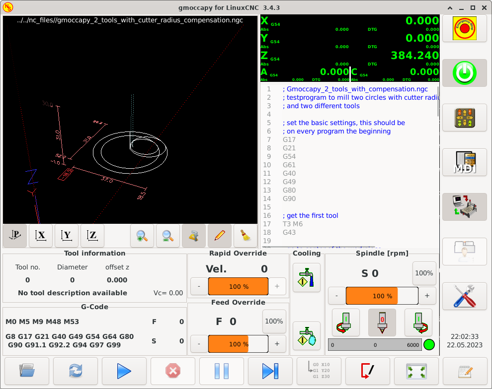
The build uses motion parts from an old silicon wafer fabrication machines, an IKEA table for the work surface, and a scavenged computer to run the show. Control is via the popular LinuxCNC software, a viable candidate for anyone doing a similar build at home. In a neat twist, the holes for hold-downs on the work table were drilled by the machine itself!
Overall it’s a tidy build, broken up over a series of videos that each go into great detail on the work involved. Interested in your own bargain CNC build? Check out this $400 setup.
Continue reading “Getting Resourceful To Build A Home CNC” →
Posted in cnc hacksTagged cnc, LinuxCNC, recycle, recyclingJune 20, 2018 by Dan Maloney
Some projects are simple, some focus on precision and craftsmanship, and some are more of the quick-and-dirty variety. This home-built CNC plasma cutter table seems to follow a “go big or go home” philosophy, and we have to say we’re mighty impressed by the finished product.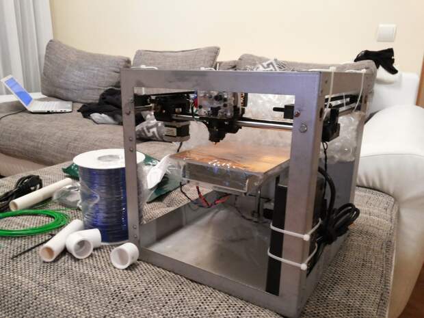
For those who follow [Bob]’s “Making Stuff” YouTube channel, this build has been a long time coming. The playlist below has eight videos that cover the entire process from cutting the first tubes of the welded frame to the initial test cuts with the finished machine. [Bob] took great pains to make the frame as square and flat as possible, to the extent of shimming a cross member to correct a 0.030″ misalignment before welding. He used good-quality linear rails for each axis, and hefty NEMA 23 steppers. There were a few false starts, like the water pan that was going to be welded out of five separate pieces of steel until the metal shop guys saved the day with their press brake. In the end, the machine turned out great; with a build cost of $2000 including the plasma cutter it’s not exactly cheap, but it’s quite a bargain compared to similar sized commercial machines.
We think the video series is a great guide for anyone looking to make a CNC plasma table. We’ve seen builds like this before, including [This Old Tony]’s CNC router.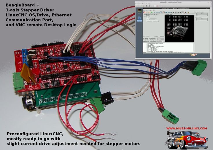 Watching these builds gives us the itch to get into the shop and start cutting metal. Continue reading “A CNC Plasma Cutter Table, From The Shop Floor Up” →
May 4, 2017 by Bryan Cockfield
They say that there’s more to a Jackson Pollock painting than randomly scattering paint on a canvas, and the auction value of his work seems to verify that claim. If you want to create some more conventional artwork, however, but are missing the artistic muse that inspired Pollock, maybe you can put your creative energies to work building a robot that will create the art for you.
[Dane Kouttron] was able to get his hands on an old SCARA robotic arm, and was recently inspired to create a paintbrush-weilding robot with it for the 2nd Annual Robot Art competition. Getting one of these ancient (circa 1983) robots working again is no easy task though.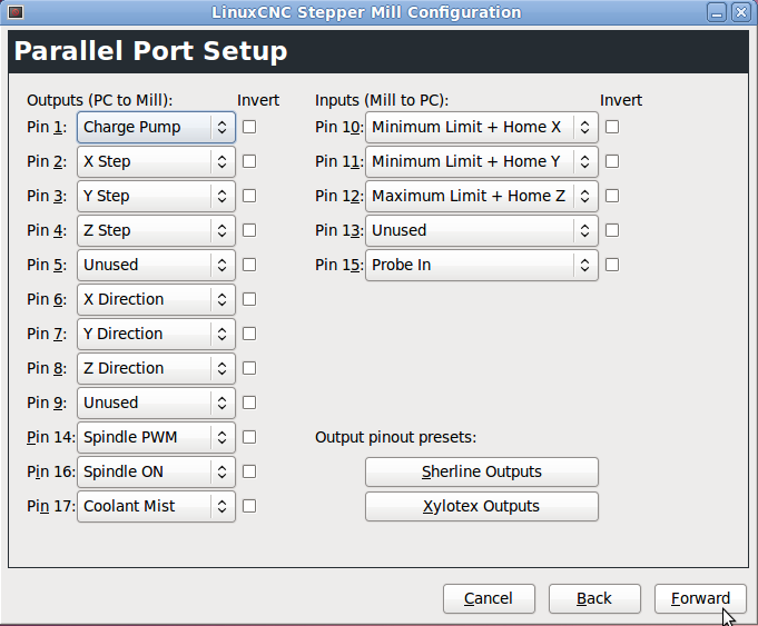 [Dane] used LinuxCNC to help reverse engineer the robot’s controls and had to build a lot of supporting hardware to get the extremely heavy robot to work properly. The entire process took around two months, and everything from color selection to paint refill to the actual painting itself is completely automated.
Be sure to check out the video after the break to see the robot in action. The writeup goes into great detail about the robot, and includes everything from reverse engineering the encoders to auto-cleaning a paintbrush. If you don’t have a SCARA robot arm in your parts drawer, though, there are lots of other options to explore for robot-created artwork.
Continue reading “Ancient Robot Creates Modern Art” →
Posted in Robots HacksTagged art, automation, contest, LinuxCNC, robot, scaraDecember 25, 2015 by Joshua Vasquez
It takes a long toolchain to take the garage-machinist-to-be through all the hoops needed to start cranking out parts. From the choice of CAD software to the CAM tools that turn 3D models into gcode, to the gcode interpretters that chew up this source code and spit out step and direction pulses to turn the cranks of a cnc mill, there’s a multitude of open-and-closed source tools to choose from and even an opportunity to develop some of our own. That’s exactly what [Nick] and the folks over on the cnc-club forums did; they’ve written their own CAM tool that enables the end user to design a procedure of cuts and toolpaths that can export to gcode compatible with LinuxCNC.
Their tool, dubbed “LinuxCNC-features”, embeds a LinuxCNC-compatible graphical gcode programming interface directly into the LinuxCNC native user interface. Creating a part is a matter of defining a list of sequential cuts along programmable toolpaths. These sequential cuts are treatments like drilled holes, square pockets, bolt holes, and lines. The native embedding enables the machinist to preview each of the 3D toolpaths in LinuxCNC’s live view, giving him-or-her a quick-and-dirty check to make sure that their gcode performs as expected before running it. [Nick] has a couple of videos to get you up-and running on either your mill or lathe.
LinuxCNC-features has been out in the wild for almost two years now, but if you’re looking to get started cranking out parts in the garage, look no further for a CAM tool that can quickly generate gcode for simple projects. In case you’re not familiar with LinuxCNC, it’s one of the most mature open-source gcode interpreters designed to turn your PC into a CNC controller, and it’s the brains behind some outstanding DIY CNC machines like this plasma cutter.
Continue reading “‘LinuxCNC-Features’ Is The Garage-Fab’s Missing CAM Tool” →
Posted in NewsTagged cam, gcode, LinuxCNCLinuxCNC: PNCconf Configuration Wizard - CNC Maniac
PNCconf is designed to help you build configurations that use specific products I/O Mesa Anything .
It can configure closed loop servo systems or hardware stepper systems.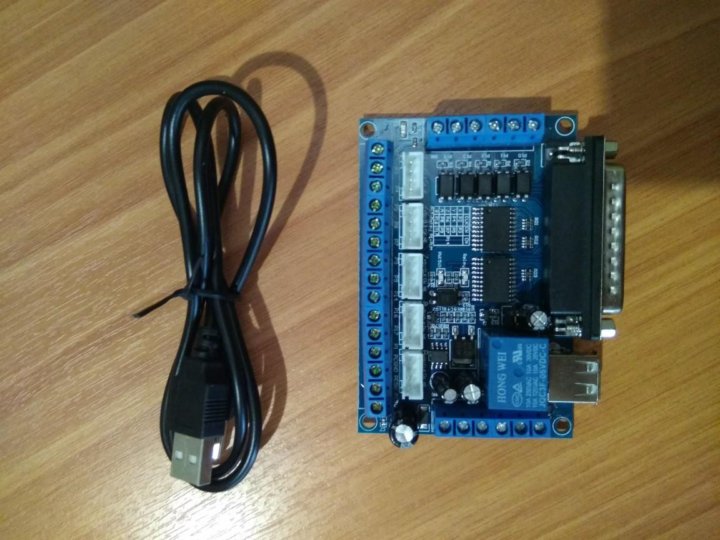 It uses the same wizard approach , as Stepconf (used for step-by-step software, parallel port controlled systems).
There are two approaches when using PNCconf:
One is to use PNCconf to permanently tune your system - if you decide to change the settings, reload PNCconf and let it set up the new settings. This will work well if your machine is fairly standard and you can use your own files to add custom features. PNCconf tries to work with you in this regard.
Another is to use PNCconf to create a configuration close to what you want and then manually edit everything to tailor it to your needs. This will be the choice if you need extensive modifications beyond the scope of PNCconf or you just want to tinker/learn about LinuxCNC.
You navigate through the wizard pages using the Forward, Back, and Cancel buttons. There is also a help button that gives some help information about pages, schemas, and the output page.
| Tooltip | The PNCconf help page should have the latest information and additional information. |
1. Step-by-step instructions
Step-by-step instructions for setting up Mesa2. Create or edit
This allows you to select a previously saved configuration or create a new one. If you select Change Configuration and click Next, a file selection box will appear. Pncconf preselects your last saved file. Select the configuration you want to edit. If you have made any changes to the core hal or ini files, Pncconf will overwrite those files and those changes will be lost. Some files will not be overwritten, and Pncconf puts a flag on these files. It also allows you to select the desktop shortcut/launcher options. The desktop shortcut will place a folder icon on the desktop pointing to your new configuration files. Otherwise, you will have to search in your home folder in linuxcnc/configs.
The desktop launcher will add an icon to the desktop to launch your configuration directly. You can also start it from the main menu by using the LinuxCNC configuration selector found in the CNC menu and selecting your configuration name.
3. Machine Basics
Machine BasicsMachine Basics
If you use a name with spaces, PNCconf will replace spaces with underscores (Linux doesn't like spaces in names). Select Axle Configuration - This selects what type of machine you are building and what axles are available. The machine unit selector allows you to enter data in metric or imperial units on the following pages.
| Tooltip | Default values are not converted when using metric, so make sure they are correct! |
Computer Response Time
Servo Period sets the system delay. Latency refers to the amount of time a computer can run longer than this period. LinuxCNC requires everything to be done within a very tight and consistent time frame, otherwise crashes will happen. LinuxCNC requires and uses operating system real-time , which simply means that it has a low latency response time when LinuxCNC requires its computations, and when LinuxCNC performs computations, it cannot be interrupted by lower priority requests (such as user input on on-screen buttons or drawing, etc. d.).
d.).
Latency checking is very important and should be checked early. Fortunately, by using the Mesa card for work that requires maximum response time (encoder counting and PWM generation), we can handle much higher latency than if we used the parallel port for these things. Standard test in LinuxCNC ( test base period jitter ) is a BASE period delay test (even if we don't use a base period). If you click the test base period jitter button, it launches the delay test window (you can also load it directly from the app/cnc panel). The test mentions to run it for a few minutes, but the longer the better. consider that 15 minutes is a minimum, and even better - a night. At this time, use the computer to boot, use the network, use USB, etc., we want to know the worst case latency and find out if any particular action affects our latency. We need to look at test base period jitter . Anything below 20000 is great - you can even do software quick stepping on a 20000 machine - 50000 is still good for software stepping and fine for us. 50000-100000 isn't really that great, but can still be used with fast response hardware cards. So we can use anything less than 100000.
| Hint | The LinuxCNC wiki has a user-composed list of hardware and latency obtained: http://wiki.linuxcnc.org/cgi-bin/wiki.pl? Latency-Test Consider adding your information to the list. There are also links on this page to information about troubleshooting some latency issues. |
Now we are happy with the delay and need to select a servo period. In most cases, a servo period of 1000000 ns is fine (which gives a servo calculation rate of 1 kHz - 1000 calculations per second) if you are making a closed loop servo system that controls torque (current) rather than speed (voltage) at a faster rate. It is better to have about 200,000 (calculated frequency 5 kHz). The problem with lowering the speed of a servo is that it leaves less time for the computer to do other things besides LinuxCNC calculations. Usually the display (GUI) becomes less responsive. You must decide on a balance. Keep in mind that if you tune a closed loop servo and then change the period of the servo, you will probably have to tune them again.
I/O Control Ports/Boards
PNCconf can configure machines with two Mesa boards and three parallel ports. Parallel ports can only be used for simple low speed (servo speed) I/O.
Mesa
You must select at least one Mesa board because PNCconf will not configure the parallel ports for encoder count, output step, or PWM signals. The mesa maps available in the selection box are based on what PNCconf finds for firmware on systems. There are options to add custom firmware and/or blacklist (ignore) some firmwares or boards using a settings file. If the firmware is not found, PNCconf will show a warning and will use the internal sample firmware - no testing will be possible. It should be noted that if you choose two PCI Mesa cards, it is currently impossible to predict which card is 0 and which is 1 - you should check - moving the cards can change their order. If you are configuring with two cards, both cards must be installed for the tests to work.
Parallel Port
Up to 3 parallel ports can be used as simple I/O ports. You must specify the parallel port address. You can enter the Linux parallel port numbering system (0,1 or 2) or enter the actual address. The address for the built-in port is often 0x0278 or 0x0378 (written in hex), but can be found on the BIOS page. The BIOS page is located when you first start your computer. To enter it, you must press a key (for example, F2). On the BIOS page, you can find the parallel port address and set the mode such as SPP, EPP, etc. On some computers, this information is displayed for a few seconds during startup. For PCI parallel port cards, the address can be found by pressing button parport address . A help output page will open with a list of all PCI devices that can be found. It should contain a link to the parallel port device with a list of addresses. One of these addresses should work. Not all PCI parallel ports work properly. Either type can be selected as in (maximum input pins) or out (maximum output pins).
GUI Front-end list
GUI Front-end list defines the graphical screens that LinuxCNC will use. Everyone has their own version.
AXIS
- fully supports lathes.
- the most developed and used interface
- is designed for use with mouse and keyboard
- is based on tkinter, so integrates PYVCP (Python-based Virtual Control Panels) naturally.
- has a 3D graphics window.
- allows integration of the VCP on the side or in the center tab
TOUCHY
- Touchy was designed to be used with a touch screen, some minimal physical switches and an MPG wheel.
- requires cycle start, interrupt and step signals and buttons
- also requires MPG common axis jog selection.
- is based on GTK so it naturally integrates GLADE VCPs (Virtual Control Panels).
- allows VCP panels to be integrated into the center tab
- does not have a graphic window
- the appearance can be changed with custom themes
MINI
- standard on Sherline OEM machines
- no integration with Estop
- does not use Estop 90 V14 90
- hello contrast bright blue screen
- separate graphics window
- no VCP integration
- Homing before MDI / start
- If you want to be able to move the machine before homing, uncheck this box.
- Tool tip tooltip
- Choose between prompting for a tool change screen or exporting standard signal names for a custom tool change Hal file.
- Choose between prompting for a tool change screen or exporting standard signal names for a custom tool change Hal file.
TkLinuxCNC
4. External configuration
This page allows you to select external controls, for example for rapid traverse or cancel.
PNCconf external configuration If you select a joystick to move, it will always be connected to LinuxCNC for booting. In order to use the analog sticks for useful movement, you will probably need to add your own HAL code. MPG jog requires a pulse generator connected to the MESA encoder counter. Either a pulse generator (MPG) or switches (such as a rotary switch) can be used to control the interlock. The external buttons can be used with the stock switch-based joystick.
Joystick jogging
Requires custom device rule to be installed on the system. This is the file that LinuxCNC uses to connect to a list of LINUX devices. PNCconf will help make this file.
Search for device rule ( Search for device rule ) will search the system for rules, you can use this to find device names you already created with PNCconf.
Add a device rule ( Add a device rule ) will allow you to configure a new device by following the prompts. You will need your device.
Test device ( test device ) allows you to boot a device, see its contact names and test its functions with a HALmeter.
Joystick uses HALUI and hal_input components.
External buttons
Allows you to move the axis with simple buttons at a given speed. Probably best for fast travel.
MPG Jogging
Allows the use of a manual pulse generator to move the machine axis.
MPG is often found on commercial grade cars. They provide quadrature pulses that can be counted using the MESA encoder counter. PNCconf allows you to use an MPG for each axis, or one MPG common to all axes. This allows you to select jog speed with switches or single speed.
The selectable increment option uses the mux16 component. This component has options such as Reaction and Gray Code to help filter out the raw switch input.
Overrides
PNCconf allows you to change the feedrate and/or spindle speed using a pulse generator (MPG) or switches (eg rotary).
5. GUI configuration.
Here you can set default values for display screens, add virtual control panels (VCPs), and set some LinuxCNC options.
PNCconf GUI ConfigurationFront-end GUI Options
Default Options allows you to select general default options for any screen.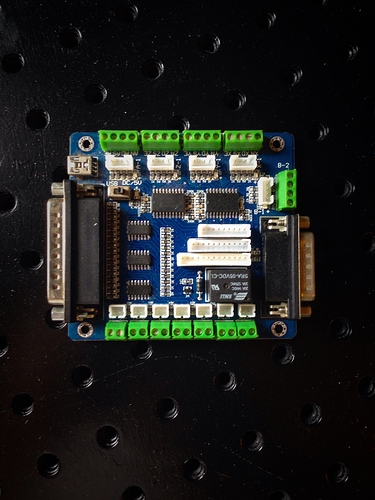
AXIS default values are AXIS specific settings. If you choose size, position, or forced deployment options, PNCconf asks if the settings file (.axisrc) can be overwritten. If you didn't manually add commands to this file, that's fine. Position and maximum force can be used to move AXIS to a second monitor if the system supports this feature.
Touchy default settings are Touchy specific settings. Most Touchy settings can be changed while Touchy is running using the settings page. Touchy uses GTK for screen rendering, and GTK supports themes. Themes control the main appearance of the program. You can download themes from the internet or edit them yourself. The computer has a list of current themes that you can choose from. To highlight a portion of text, PNCconf allows you to override the default theme values. The position and maximum force options can be used to move the Touchy to a second monitor if the system supports it.
VCP Options
Virtual Control Panels let you add customizable controls and displays to your screen.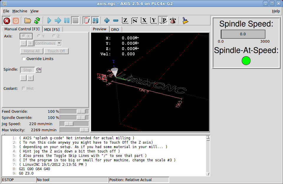 AXIS and Touchy can integrate these controls within the screen at specific locations. There are two types of VCP: pyVCP which uses Tkinter to render the screen, and GLADE VCP which uses GTK .
PyVCP
The PyVCP screen XML file can only be created manually. PyVCP fits naturally into AXIS as both use TKinter.
HAL contacts are created for connecting a user inside their user HAL file. There is a sample spindle display panel that the user can use as is or add on. You can select an empty file, which you can then add controls to widgets or select a sample spindle display that will display the spindle RPM and also indicate if the spindle is at the desired speed.
PNCconf will wire the appropriate spindle display HAL pins for you. If you are using AXIS, the panel will be integrated on the right side. If you do not use AXIS, then the panel will be separate offline from the front end of the screen.
You can use the geometry options to resize and move the panel, for example to move it to a second screen if the system supports it. If you click the button " Display sample panel " , then the size and placement parameters will be taken into account.
GLADE VCP
The GLADE VCP fits naturally into the TOUCHY screen as they both use GTK, but by changing the GLADE VCP theme you can make them blend well with AXIS.
It uses a graphical editor to create XML files. HAL contacts are created to connect a user inside their user HAL file.
GLADE VCP also allows much more sophisticated (and complex) programming interactions that PNCconf does not currently use. (See GLADE VCP in the manual)
PNCconf has sample panels that the user can use as is or use for further development. With GLADE VCP, PNCconf will allow you to select various options on your demo display.
In the " sample options " section, select which ones you need. Zero buttons use HALUI commands, which you can edit later in the HALUI section.
Automatic Z touch also requires the classic ladder program touch and the selected sensor input. This requires a conductive contact plate and a grounded conductive tool. See here for how it works.
Section Display Options » size, position, and maximum force can be used on the standalone panel for things like placing the screen on a second monitor if the system is capable.
You can select a GTK theme that defines the basic appearance of the panel. It's usually best to have this match the interface screen. These settings will be used if you click the Show sample button. With GLADE VCP, depending on the external screen, you can choose where the panel will be displayed.
You can make it standalone, or with AXIS it can be in the center or on the right side, with Touchy it can be in the center.
Defaults and options
6. Mesa configuration
The Mesa configuration pages allow you to use different firmware. On the main page you have selected the Mesa card, here you select the available firmware and choose which and how many components are available.
Mesa ConfigurationThe Parport address is only used with the Mesa Parport card, 7i43. The built-in parallel port usually uses 0x278 or 0x378, although you should be able to find the address on the BIOS page. 7i43 requires the parallel port to use the EPP mode set on the BIOS page. When using the PCI parallel port, the address can be found using the search button on the main page.
| Note | Many PCI cards do not properly support EPP. |
PDM PWM and 3PWM base frequency strike a balance between ripple and linearity. When using Mesa daughter cards, the card documentation should provide guidance.
| Important | It is important to follow them to avoid damage and maximize performance.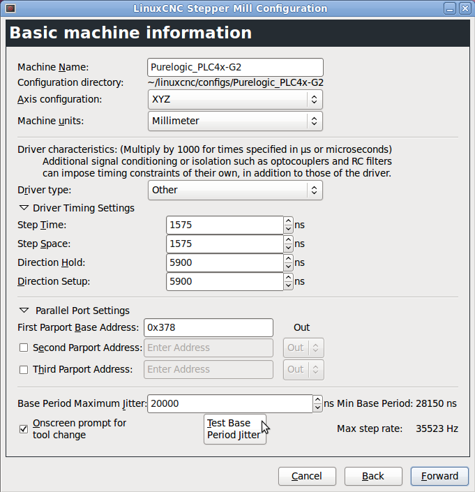 |
The 7i33 requires PDM and a PDM base frequency of 6 mHz The 7i29requires PWM and a PWM base frequency of 20 Khz The 7i30 requires PWM and a PWM base frequency of 20 Khz The 7i40 requires PWM and a PWM base frequency of 50 Khz The 7i48 requires UDM and a PWM base frequency of 24 Khz
The watchdog timeout is used to set how long the MESA board will wait before turning off outputs if communication with the computer is interrupted. Please remember that Mesa uses active low outputs, which means that when the output pin is on it is low (approximately 0 volts), and if it is turned off the output is high (approximately 5 volts), make sure your equipment is safe. when it is off.
You can select the number of available components by deselecting those not in use. Not all component types are available for all firmwares.
Selecting less than the maximum number of components allows more GPIO pins. When using daughter cards, remember that you cannot deselect the pins that the card uses. For example, some firmware supports two 7i33 cards. If you only have one, you can deselect enough components to use a connector that supports the second 7i33. Components are canceled numerically, first by highest number, then in descending order without missing a number. If the components are not where you want them to be, you must use a different firmware. The firmware dictates where, what and the maximum number of components. Using custom firmware in PNCconf requires special procedures and is not always possible.
After selecting all of these options, click the Accept Component Changes button and PNCconf will update the I/O setup pages. Available connectors will only show I/O tabs, depending on the Mesa board.
7. Configuring Mesa I/O
Tabs are used to configure the input and output pins of the Mesa boards. PNCconf allows you to create your own signal names for use in custom HAL files.
Mesa 9 I/O setup0002 On this tab with this firmware, the components are configured for the 7i33 daughterboard, commonly used with closed loop servos. Note that the encoder counter and PWM driver part numbers are not listed in numerical order. This is in line with the requirements of the daughter board. Mesa I/O C3
 This tab has all GPIO pins. Pay attention to the three-digit numbers - they will correspond to the HAL output number. GPIO pins can be selected as input or output and can be inverted.
Mesa I/O C4This tab has a mixture of steppers and GPIOs. The output and guide pins of step generators can be inverted. Note that inverting the Step Gen-A pin (output step pin) changes the timing of the step. It should match your controller's expectations.
8. Parport Configuration
Parport Configuration PNCconfThe parallel port can be used for simple I/O, just like the Mesa GPIO pins.
9. Axis configuration
Axis configuration PNCconf This page allows you to configure and test the motor and/or encoder combination. When using a servomotor, an open loop test is available, when using a stepper motor, a tuning test is available.
Open loop test
The open loop test is important because it confirms the motor and encoder direction. The motor must move the axis in the positive direction when the positive button is pressed, and the encoder must also count in the positive direction. The movement of the axis must comply with the standards of the Machinery Manual, otherwise the AXIS graphic display will not make much sense. Note that the directions of the axes are based on the movement of the TOOL, not the movement of the table. There is no acceleration ramp when testing in open loop, so start with lower DAC numbers. By moving the axis a known distance, the encoder scaling can be confirmed. The encoder should count even without the amplifier turned on, depending on how the encoder is powered.
| Warning | If the motor and encoder do not match the counting direction, the servo will run away when using PID control. |
Since the PID settings cannot be tested in PNCconf at the moment, the settings are really meant to be reconfigured - enter your tested PID settings.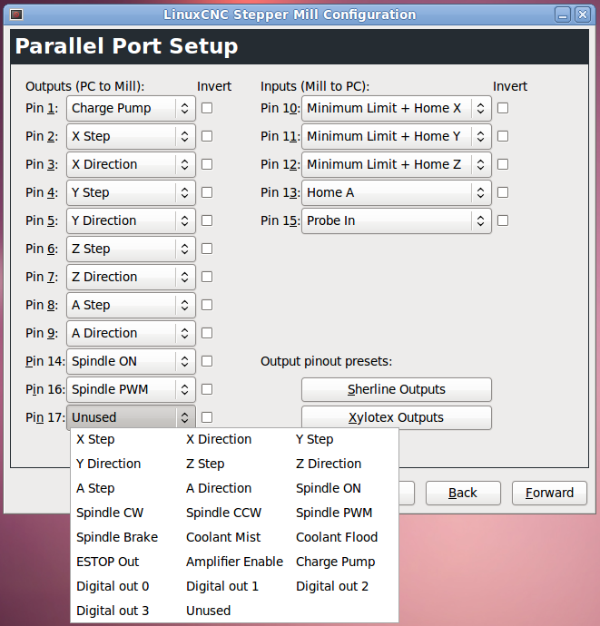
DAC scaling, maximum output and offset are used to adjust the DAC output.
Calculate DAC
These two values are the scaling and offset factors for outputting the axis to the motor amplifiers. The second value (offset) is subtracted from the calculated output (in volts) and divided by the first value (scale factor) before being written to the D/A converters. The scale units are in volts per DAC output voltage. The units for the offset value are in volts. They can be used to linearize the DAC.
Specifically, when writing Linux output, the CNC first converts the desired output signal in quasi-SI units to raw actuator values, such as volts for an amplifier DAC. This scaling looks like this: The scale value can be obtained analytically by performing a unit analysis, i.e. the units are [output SI units] / [actuator units]. For example, on a car with a speed boost where 1 volt gives a speed of 250 mm/sec. Note that displacement units are expressed in machine units, e.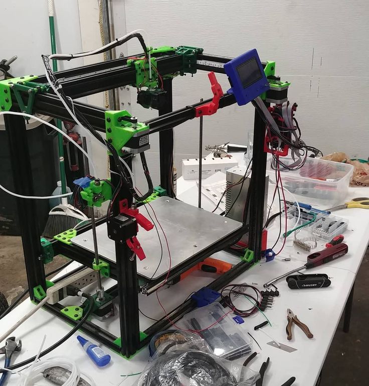 g. mm/sec, and they are pre-subtracted from the read sensor. The value of this offset is obtained by finding the value of your output, which gives 0.0 for the output of the drive. If the DAC is linearized, this offset is typically 0.0.
Scale and offset can also be used to linearize the DAC, resulting in values that reflect the combined effects of gain, DAC non-linearity, DAC units, etc. To do this, perform the following procedure:
- Create a calibration table for the output by driving the DAC with desired voltage and measuring result:
| 3 | |
| -9 | -8,83 |
| 0 | -0,96 |
| 1 | -0,03 |
| 9 | 9.87 |
| 10 | 10.07 |
- Perform linear approximation by the lowest squares to get such coefficients A, B, that MES = A * desired + B
- pay attention to us that we are attention we need the raw output so that our measured output is identical to the command output.
 It means
 - cmd = a * desired + b
- desired = (cmd-b) / a
- As a result, the coefficients a and b from the linear approximation can be used directly as scale and offset for the controller.
MMAX OUTPUT: maximum value for the PID compensation output written to the motor amplifier, in volts. The calculated output value is limited by this limit. The limit is applied before scaling to the original output units. The value is applied symmetrically to both plus and minus.
Tuning Test Unfortunately, the tuning test only works with stepper systems. Confirm that the direction of the axis is correct again. Then test the system by rotating the axle back and forth. If the acceleration or top speed is too high, you will lose steps. When moving, be aware that it may take some time for the axis to stop at low acceleration. The limit switches do not work during this test. You can set the pause time. This will allow you to adjust and read the dial indicator to see if you are losing steps.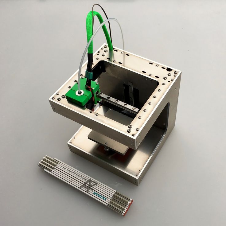
Stepper Timing must be adapted to the requirements of the stepper controller. Pncconf provides some default controller timing options or allows you to customize the timing options. See Stepper_Drive_Timing for more known timings (feel free to add the ones you figured out). When in doubt, use large numbers like 5000, this will only limit the maximum speed.
Brushless Motor Control ( Brushless motor control) These parameters are used to provide low level control of brushless motors with special firmware and daughter cards. It also allows HAL sensors to be converted from one manufacturer to another. It is only partially supported and one will be needed to complete HAL connections.
PNCconf axis scale calculation Scale parameters can be entered directly or the scale calculation button can be used for assistance . Use the checkboxes to select the appropriate calculations. Note that pulley teeth require the number of teeth, not the gear ratio.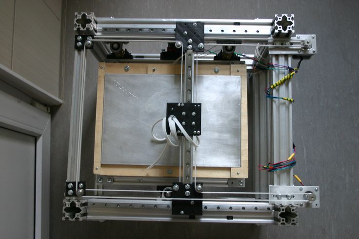 If you are satisfied with the scale, click Apply, otherwise click Cancel and enter the scale directly.
Also on the schematic tab are two examples of home switches and limit switches. These are two examples of many different ways to set the reference point and limits.
| Important | It is very important to start with the axis moving in the right direction, otherwise it will be very difficult to get the right return to the starting position! |
Remember that the positive and negative directions refer to TOOLS, not to the table.
On a typical mill
- when the table is extended, this is the positive Y direction
- when the table moves to the left, this is the positive X direction
- when the table moves down, this is the positive direction Z
- when the spindle moves up, this is the positive direction Z
On a typical lathe
- when the TOOL moves to the right, from the chuck it is the positive direction this is the positive X direction.
 Some lathes have an X opposite (such as the tool on the back side), this will work fine, but the AXIS graphic display cannot reflect this.
When using homing switches and/or limit switches, LinuxCNC expects HAL signals to be true when the switch is pressed/operated. If the signal for the limit switch is wrong, then LinuxCNC will think that the machine is running at its limit all the time. If the home trailer search logic is wrong, LinuxCNC will move in the wrong direction. In fact, it will try to turn off the home switch.
Determine the position of the limit switch.
Limit switches are backup software limits in case something happens to the electronics, like a servo running away. Limit switches should be placed so that the machine does not touch the physical end of the axis movement. Remember that when moving fast, the axle will move past the point of contact. Limit switches on the machine must be in active lower position. For example, power is constantly flowing through the switches - a power loss (open switch) is triggered. Although you can connect them in another way, it is safe. May need to be inverted so that the HAL signal in LinuxCNC is at active high. - TRUE means that the switch has tripped. When running LinuxCNC, if you get a limit warning and the axis does NOT fire, inverting the signal is probably the solution. (use HALMETER to check the corresponding HAL signal, eg eg. joint.0.pos-lim-sw-in X axis positive limit switch)
Decide on the location of the home switch.
If you use limit switches, you can also use them as a home switch. A separate home switch is useful if you have a long axle that is typically used far from the limit switches, or moving the axle towards the ends creates collision problems with material. for example, a long shaft in a lathe makes it difficult to return to the home position without the tool hitting the shaft, so a separate home switch closer to the middle may be better. If you have an encoder with an index, then the home position switch acts as the home course and the index will be the actual home location.
Determine the machine coordinate zero position.
MACHINE ORIGIN is what LinuxCNC uses to refer to all user coordinate systems. I can't think of a reason why it could be in any particular location. There are only a few G codes that can access the MACHINE COORDINATE system (G53, G30 and G28). When using the tool change option on the G30, it can be convenient to have the origin at the tool change position. By convention, it's easiest to set ORIGIN on the home switch.
Determine the (final) home position (HOME POSITION)
This function simply places the caret in a permanent and comfortable position after LinuxCNC determines where ORIGIN is.
Measure / calculate the travel distances of the positive / negative axis.
Move the axis to the origin. Mark a link on the movable caliper and fixed mount (so they are in line) to move the machine to the extremes. Measure one of the distances traveled between the marks. Move the table to the other end of the path. Measure the marks again. If ORIGIN is at one of the limits, then this travel distance will be zero.(machine)
MACHINE ORIGIN
The origin is the MACHINE origin. (not the zero point where you set the cutter/material). LinuxCNC uses this dot to refer to everything else. It must be within the software. LinuxCNC uses the position of the home switch to calculate the home position (when using home switches or must be set manually if not using home switches.
Travel distance
This is the maximum distance the axle can travel in each direction. This can be measured directly from the source to the limit switch. The positive and negative travel distance must be the total travel distance.
POSITIVE TRAVEL DISTANCE
This is the distance that the axis travels from the origin to the positive travel distance or total travel minus the negative travel distance. You must set this value to zero if the origin is at the positive limit. Will always be zero or a positive number.
NEGATIVE TRAVEL DISTANCE
This is the distance the axis travels from the origin to the negative travel distance. Or the total travel minus the positive travel distance. You must set this value to zero if the origin is at the negative limit. It will always be zero or a negative number. If you forget to make it negative, PNCconf will do it internally.
HOME POSITION
This is the position where the original sequence ends. It is referenced from the source, so it can be negative or positive depending on which side of the source it is located. In the (final) home position, if you have to move in a positive direction to get to the origin, the number will be negative.
HOME SWITCH LOCATION
This is the distance from the Home switch to Origin. It can be negative or positive, depending on which side it is on. When at the home switch location, if you have to move in a positive direction to get to the starting point, the number will be negative. If you set this value to zero, then the origin will be at the location of the limit switch (plus the index lookup distance, if used).
Home point search speed
Home point search speed in units per minute.
Home search direction
Sets the home switch search direction to either negative (i.e. towards the negative limit switch) or positive (towards the positive limit switch).
Home speed reference point
Fine Home search speed in units per minute
End speed
Speed used from home point position to (end) home position in units per minute. Set to 0 for maximum fast speed
Use Comp. File
Allows you to specify the file name and type of Comp. Provides complex compensation. See Section AXIS in the INI chapter. Use Backlash Compensation
Allows you to set a simple backlash compensation. Cannot be used with compensation file. See the AXIS section in the INI chapter.
AXISReference Chart The charts should help to show an example of limit switches and standard axis movement directions. In this example, the Z axis was with two limit switches, the positive switch being used as the home switch. The zero point is at the negative limit. The left end of the carriage is the negative actuation pin and the right end is the positive actuation pin. We want the FINAL HOME POSITION to be 4 inches from the start on the positive side. If the carriage was moved to the positive limit, we would measure 10 inches between the negative limit and the negative trip pin.
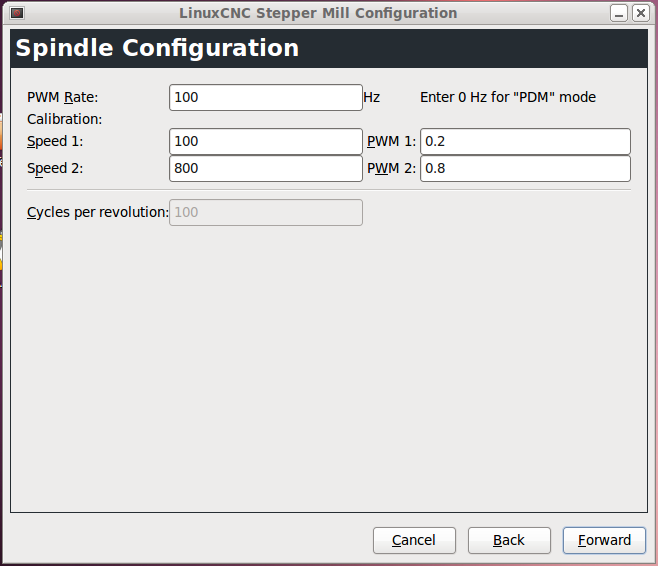
10. Spindle configuration
If you select spindle signals, this page is available to configure spindle control.
| Tooltip | Many of the options on this page will not display unless the correct option was selected on the previous pages! |
This page is similar to the axis motor configuration page.
There are some differences:
- If no stepping spindle is selected, there are no acceleration or speed limits.
- No gear or range support.
- If you have selected the VCP spindle display option, then the spindle speed bar and filter settings can be displayed.
- Spindle speed allows LinuxCNC to wait for the spindle to reach the desired speed before moving the axis. This is especially useful on lathes with a constant surface feed and a large change in speed diameter. This requires either feedback from the encoder or a digital spindle speed signal, usually connected to the VFD.
- When using encoder feedback, you can select a spindle speed scale setting that indicates how close the actual speed is to the requested speed to be considered at speed.
- When using encoder feedback, the VCP speed display may be unstable - a filter setting can be used to smooth the display. The encoder scale must be set to match the encoder counter/transmission being used.
- If you are using a single spindle encoder input, you must add the line: setp hm2_7i43.0.encoder.00.counter-mode 1 (change board name and encoder number to suit your requirements) to the user HAL file. See the Encoders section of Hostmot2 for more information on counter mode.
11. Advanced Options
This section allows you to configure HALUI commands and download classic programs and Ladder program examples. If you have selected GLADE VCP options, such as axis zeroing, commands will be displayed. See the HALUI chapter for more information on using custom settings. There are several options for ladder logic. The Estop program allows an external ESTOP switch or GUI to issue Estop. It also has a synchronized grease pump signal. Automatic Z touch is done with a flip plate, GLADE VCP touch button and HALUI specific commands to set current user source to zero and quick reset. The Modbus serial interface program is essentially an empty template program that sets up the classic interface for the Modbus serial interface. See the Classicladder chapter in the manual.
12. HAL Components
On this page you can add additional HAL components that may be needed for custom HAL files. Thus, there is no need to manually edit the main HAL file while still allowing the user the required components.
PNCconf HAL ComponentsThe first choice is the components that pncconf uses internally. You can configure pncconf to load additional component instances for your custom HAL file.
Select the number of instances your user file will need, pncconf will add what it needs after them.
This means that if you need 2 and pncconf needs 1, pncconf will load 3 instances and use the last one.
Custom component commands
This selection will allow you to load HAL components that pncconf does not use. Add the loadrt or loadusr command under heading load command. Add addf command under heading Command thread. Components will be added to the stream between reading inputs and writing outputs in the order you write them in command of stream .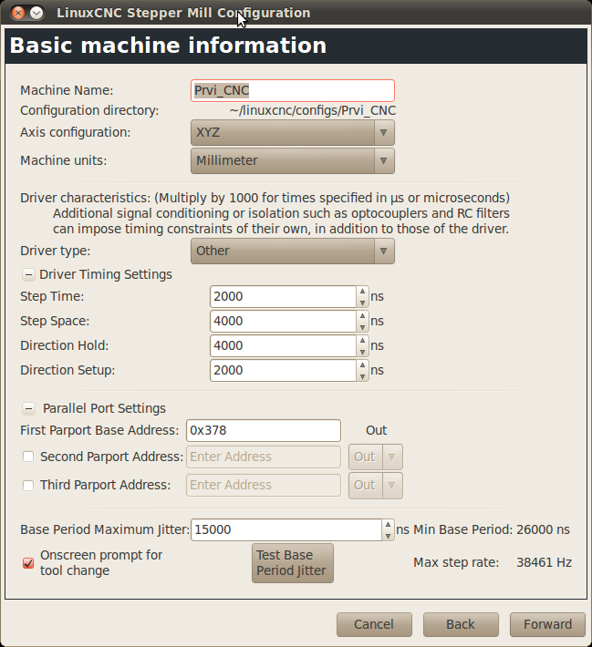
13. Advanced use of PNCconf
PNCconf does its best to allow user flexibility. PNCconf supports custom signal names, custom component loading, custom HAL files, and custom firmware.
There are also signal names that PNCconf always provides regardless of the options selected for user HAL files. Some people think that most of the settings should work regardless of whether you later choose other options in PNCconf.
In the end, if the settings are out of scope for PNCconf, you can use PNCconf to create a basic configuration, or use one of the sample LinuxCNC configurations and just manually edit it the way you want.
Custom signal names
If you want to connect the component to something in a custom HAL file, write a unique signal name in the combo box. Some components will add endings to your custom signal name:
User-defined signal names
The Hal Components page can be used to download components required by the user for configuration.
Loading custom firmware
PNCconf looks for firmware on the system and then looks for an XML file that it can convert to something it understands. These XML files are only supplied for officially released firmware from the LinuxCNC team. To use custom firmware, you need to convert it to an array that PNCconf understands and add the path to it in the PNCconf configuration file. By default, this path looks on the desktop for a folder named custom_firmware and a file named firmware.py.
A hidden preferences file is located in the user's home file called .pncconf-preferences and requires hidden files to be shown in order to be seen and edited. The contents of this file can be seen when PNCconf is loaded for the first time - click the help button and see the output page.
Custom HAL files
There are four custom files you can use to add HAL commands:
- custom.hal is for HAL commands that don't need to be run after the GUI has loaded.
 It runs after the HAL file with the configuration name.
 - custom_postgui.hal is for commands to be executed after AXIS is loaded or PYVCP standalone display is loaded.
- custom_gvcp.hal is for commands to be run after the Glade VCP is loaded.
- shutdown.hal is for commands to be run on LinuxCNC controlled shutdown.
Machine control setup via LPT parallel port. Stepconf
LinuxCNC can control a wide range of hardware using many different hardware interfaces. Stepconf is a program that generates configuration files for LinuxCNC for a specific class of CNC machines: those controlled via standard parallel port and controlled by signals like step & direction .
Stepconf is installed when installing LinuxCNC and is located in the CNC menu.
Stepconf puts a file in the linuxcnc/config directory to store options for each configuration you create. When you change something, you need to select the file that matches the name of your configuration. The file extension is .stepconf.
The Stepconf Wizard works best with a screen resolution of at least 800 x 600.
Stepconf start page
Stepconf start page- Create New - Creates a new configuration.
- Modify - change an existing configuration. After selecting this option, a file selection pop-up appears, in which you can select the .stepconf file to modify. If you have made any changes to the main .hal or .ini file, they will be lost. The Stepconf wizard will not modify custom.hal and custom_postgui.hal modifications. Stepconf will highlight the last created configuration file.
- Import - Import the Mach config file and try to convert it to a linuxcnc config file. After the import, you will go through the stepconf pages to confirm/change the entries. The original mach xml file will not be modified.
These settings will be written to the configuration file for the next stepconf run.
- Create Desktop Shortcut - a link to the files will be placed on your desktop.
- Create Desktop Launcher - This will place a launcher on the desktop to launch your application.
- Create Simulated Hardware - This allows you to create a configuration for testing even if you don't have real hardware.
Stepconf Basic Information
Stepconf Basic Information- Machine Name - Select a name for your machine. Use only uppercase letters, lowercase letters, numbers, - and _.
- Axis Configuration - Select XYZ (Mill), XYZA (4-Axis Mill), or XZ (Lathe).
- Machine Units - select inches or mm. All subsequent entries will be in the selected units. Changing this setting also changes the default values in the Axes section. If you change this after selecting values in any of the axes sections, they will be overwritten with the default values of the selected units.
- Driver Type - If you have one of the stepper motor drivers listed in the drop-down list, select it. Otherwise select " Other", find the timing values in your driver data sheet and enter them as nanoseconds in " Driver Timing Settings " . If the value in the datasheet is in microseconds, multiply it by 1000. For example, enter 4.5 µs as 4500 ns.
A list of some popular drivers along with their times can be found on the LinuxCNC.org Wiki under Stepper Drive Timing.
Additional signal processing or isolation, such as optocouplers and RC filters on output boards, may impose their own timing restrictions in addition to those of the driver. You may need to add time to disk requirements to account for this.
The LinuxCNC configuration selector has already configured configurations for Sherline.
- Step Time Pulse step in nanoseconds. If you are unsure about this setting, a value of 20,000 will work for most machines.
- Step Space is the minimum time between step pulses in nanoseconds. If you are unsure about this setting, a value of 20,000 will work for most machines.
- Direction Hold - how long the direction indicator is held after the direction change in nanoseconds. If you are unsure about this setting, a value of 20,000 will work for most machines.
- Direction Setup - How long before the direction changes after the last step pulse in nanoseconds. If you are unsure about this setting, a value of 20,000 will work for most machines.
- One / Two Parport - Select how many parallel ports to configure.
- Base Period Maximum Jitter - Enter the delay test result here. To start the delay test, press the button Test Base Period Jitter . For more information, see the Checking Delay section.
- Max Step Rate - Stepconf automatically calculates the maximum step rate based on the driver characteristics entered and the latency test result.

- Min Base Period - Stepconf automatically determines the minimum base period based on the entered driver characteristics and the latency test result.
Delay test
During the test, load the computer . Move windows around the screen. Climb on the Internet. Copy some large files to disk. Turn on the music. Run an OpenGL program such as glxgears. The idea is to test the PC while the latency test checks what the worst numbers are. Run the test for at least a few minutes. The longer you run the test, the better it will catch events that may occur at shorter intervals. This is a test for your computer only, so you don't need to connect any hardware to run it.
Warning: Do not attempt to start LinuxCNC while the delay test is running.
Stepconf latency test Latency is the time it takes for the PC to stop its actions and respond to an external request. In our case, the request is a periodic heartbeat, which serves as a timing reference for step pulses. The shorter the delay, the faster you can start the heartbeat and the faster and smoother the step impulses will be.
Latency is more important than processor speed. CPU is not the only factor that determines latency. Motherboards, video cards, USB ports, SMI issues, and a number of other things can affect latency.
Fixing real-time problems caused by SMI in Ubuntu
http://wiki.linuxcnc.org/cgi-bin/wiki.pl?FixingSMIIssues
The important numbers are max jitter . In the example above, 9075 nanoseconds or 9.075 microseconds is the highest jitter. Write down this number and enter it in the field " max jitter" base period.
If your max jitter is less than about 15-20 microseconds (15000-20000 nanoseconds), the computer should give very good results with software stepping. If the maximum latency is greater than 30-50 microseconds, you can still get good results, but your maximum cadence can be a little disappointing, especially if you are using microstepping or very fine pitch leadscrews.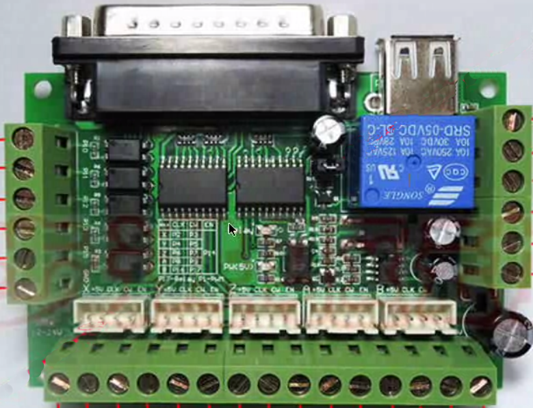 If the numbers are 100 µs or more (100,000 nanoseconds), then the PC is not a good candidate for software stepping. Numbers over 1 millisecond (1000000 nanoseconds) mean that the PC is not a good candidate for LinuxCNC, whether you use software stepping or not.
Parallel port setting
Parallel port settingYou can specify the address in hexadecimal format (often 0x378) or as the Linux default port number (possibly 0).
For each pin, select the signal that matches your parallel port pinout. Enable the invert checkbox if the signal is inverted (0V for true/active, 5V for false/inactive).
- Output pinout presets - Automatic setting of pins 2 to 9 according to Sherline standard (direction to pins 2, 4, 6, 8) or Xylotex standard (direction to pins 3, 5, 7, 9).
- Inputs and Outputs - If the input or output is not used, set the parameter to Unused .
- B External E Stop - it can be selected from the drop-down list of input contacts.
 A typical E Stop circuit uses all normally closed contacts.
 - Homing & Limit Switches - These can be selected from the input contact drop-down list for most configurations.
- Charge Pump - If your driver board requires a charger signal, select " Charge Pump " from the drop-down list for the output pin you want to connect to the charge input. The charger output is connected to the main thread using Stepconf.
Parallel Port 2 Setup
Parallel Port 2 Setup The second parallel port (if selected) can be configured and its pins are assigned on this page.
Unable to select pitch and direction signals.
You can select an input or output to maximize the number of available input/output contacts.
You can specify the address in hexadecimal format (often 0x378) or as the default port number on Linux (possibly 1).
Axis Configuration
Stepconf Axis Configuration- Steps Per Revolution Motor is the number of full steps per revolution.
 If you know how many degrees per step the motor has (for example, 1.8 degrees), divide 360 by degrees per step to find the number of steps per revolution of the motor.
 - Driver Microstepping is the number of microstepping performed by the driver. Enter 2 for a half step.
- Pulley Ratio - If your machine has pulleys between the motor and lead screw, enter the ratio here. If not, enter 1:1 .
- Leadscrew Pitch — Enter the lead screw pitch here. If you selected inches , enter the number of threads per inch. If you selected millimeters , enter the number of millimeters per revolution (for example, enter 2 for 2 mm/rev). If the machine moves in the wrong direction, enter a negative number here instead of a positive number, or reverse the guide pin for the axis.
- Maximum Velocity - Enter the maximum speed of the axis in units per second.

- Maximum Acceleration - The correct values for these elements can only be determined experimentally. See Finding the maximum speed to set the speed and Finding the maximum acceleration to set the acceleration.
- Home Location is the position to which the machine moves after completing the homing procedure for this axis. For machines without home switches, this is where the operator manually moves the machine before pressing the home button. If you combine the home and limit switches, you must move the switch to the home position or you will get a joint limit error.
- Table Travel is the travel range of this axis depending on the origin of the machine. The home location must be within table travel and not be the same as one of the table travel values.
- Home Switch Location is the location where the home switch activates or deactivates relative to the home point of the machine.
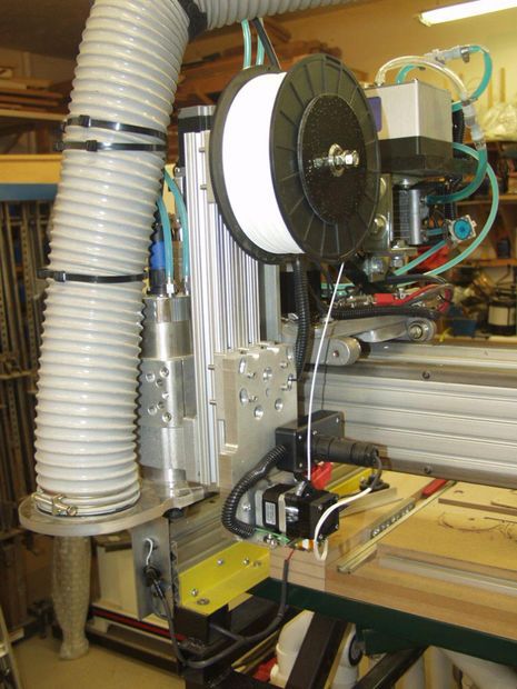 This item and the two below only appear if home switches have been selected in the parallel port pinout. If you combine the home and limit switches, the position of the home switch cannot be the same as the home, otherwise you will get a joint limit error.
 - Home Search Velocity The speed used when searching for the home switch. If the switch is near the end of travel, this speed must be selected so that the axle can decelerate to a stop before it reaches the end of travel. If the switch is only closed for a short range of travel (instead of being closed from the actuation point to one end of travel), this speed should be chosen so that the axle can decelerate to a stop before the switch opens again, and should always start from on the same side of the switch. If the machine is moving in the wrong direction at the beginning of the homing procedure, cancel the home search speed .
- Home Latch Direction - Select Same, to disengage the axis from the switch, then approach it again at very low speed.
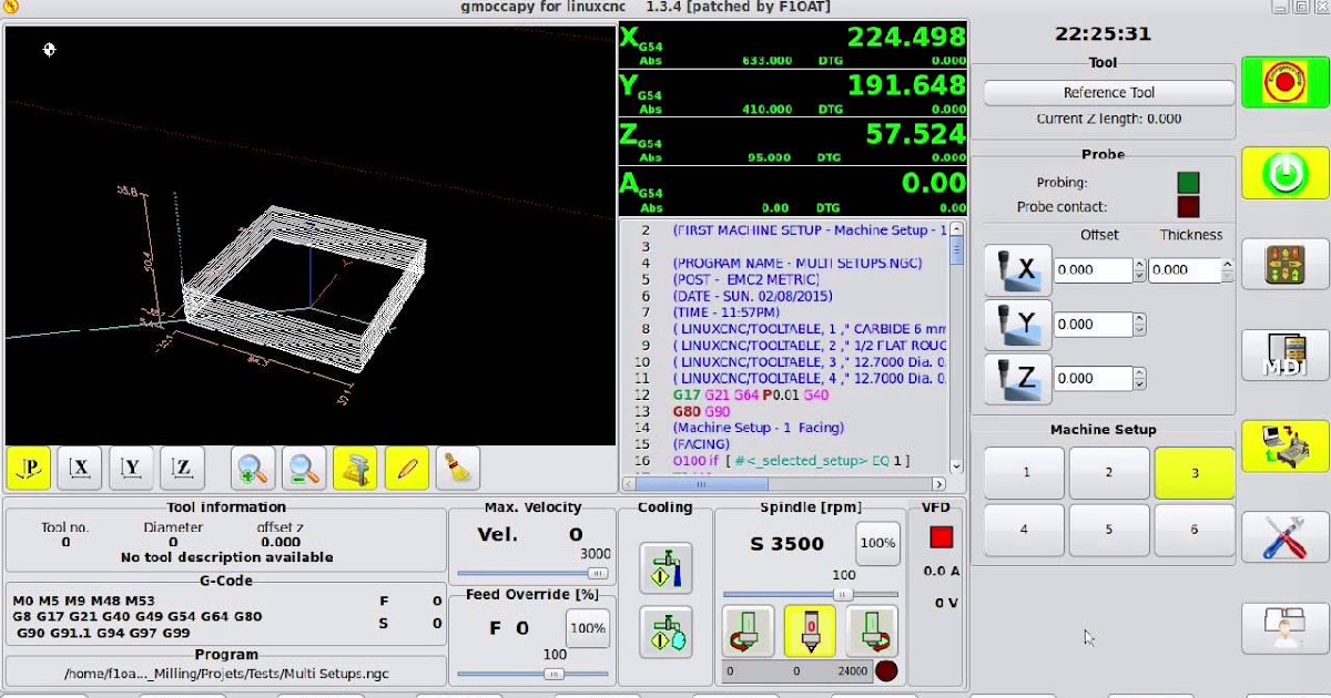 The second time the switch is turned on, the initial position is set. Select Opposite, to make the axis disengage from the switch again, and when the switch opens, the home position is set.
 - Time to accelerate to max speed - time to reach maximum speed, calculated based on maximum acceleration and maximum speed .
- Distance to accelerate to max speed Distance to accelerate to max speed from standstill.
- Pulse rate at max speed - The information is calculated based on the values entered above. The highest maximum speed pulse rate determines BASE_PERIOD . Values above 20000 Hz may cause slow response times or even freezes (the fastest usable heart rate varies by computer)
- Axis SCALE - The number to be used in the [SCALE] ini file setting. This is the number of steps per user unit.
- Test this axis - a window will open in which you can test for each axis.
 It can be used after filling in all the information for that axis.
Test axis
Test axisTest this axis is a basic tester that only outputs pitch and direction signals to try different values for acceleration and speed.
Finding the maximum speed
Start with a little acceleration and the speed you hope to achieve. Use the available buttons to move the axis closer to the center of movement. Be careful, because with a low acceleration value, the axis can travel a surprising distance to slow down to a complete stop.
After measuring the available distance, enter the safety distance in the test area, bearing in mind that the motor may start moving in an unexpected direction after stopping. Then click Run. The machine will move forward and backward on that axis. In this test, it is important that the combination of acceleration and test area allows the car to reach the selected speed and cruise for at least a short distance - the longer the distance, the better this test.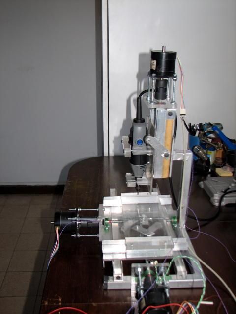 Formula
 d = 0.5 * v * v/a gives the minimum distance required to reach the given speed with the given acceleration. If it is convenient and safe to do so, push the table against the direction of travel to simulate cutting forces. If the machine slips, reduce speed and run the test again.
If the machine does not stop, turn off the " Run" button . The axis now returns to its original position. If the position is not correct, the axis has stalled or lost steps during the test. Reduce the speed and run the test again.
If the machine does not move, stops or loses steps, no matter how low you turn the speed, check the following:
- Proper stepping signal timing
- Proper pinout, including invert step pins
- Correct, good shielded wiring
- Physical problems with the motor, motor coupling, lead screw, etc.
Once you have found the speed at which the axle does not stop or lose steps during this test procedure, reduce it by 10% and use her as maximum speed axis.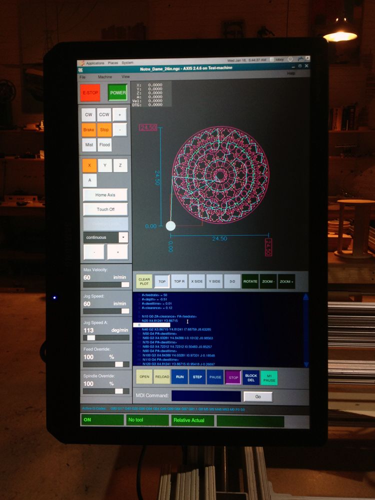 Looking for maximum acceleration
Using the maximum speed you found in the previous step, enter the acceleration value to test. Using the same procedure as above, increase or decrease the acceleration value as needed. In this test, it is important that the combination of acceleration and test area allows the car to reach the selected speed. Once you find a value at which the axis does not stop or lose steps during this test procedure, decrease it by 10% and use it as the maximum axis acceleration.
LinuxCNC Spindle Configuration Stepconf
LinuxCNC Spindle Configuration StepconfThis page only appears if " Parallel Port Pin Assignment " page has " Spindle PWM" selected for one of the outputs.
Spindle speed control
If the pinout shows spindle PWM , the following information must be entered:
- PWM speed - Carrier frequency PWM signal per spindle. Enter 0 for PDM mode, which is useful for generating an analog control voltage.
 Refer to the documentation for the spindle controller for the correct value.
 - Speed 1 and 2, PWM 1 and 2 - The generated configuration file uses a simple linear relationship to determine the PWM value for a given RPM value. If the values are unknown, they can be determined. For more information, see Spindle Calibration Definition.
Motion synchronized with the spindle
When the corresponding signals from the spindle encoder are connected to LinuxCNC via HAL, LinuxCNC supports threading on the lathe. These signals are:
- Spindle Index is the pulse that occurs once per spindle revolution.
- Spindle Phase A is the pulse that occurs at several equidistant locations as the spindle rotates.
- Spindle Phase B (Optional) is the second pulse that occurs but is offset from spindle phase A. The benefits of using both A and B are direction detection, increased noise immunity, and increased resolution.
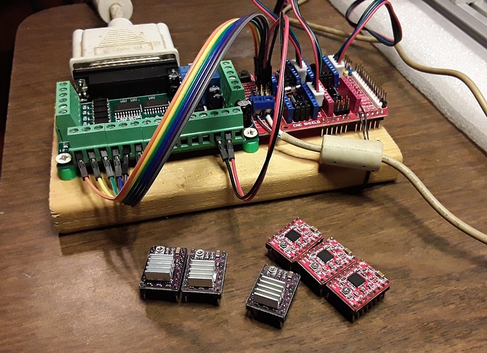
If spindle phase A and spindle index appear on the pinout, the following information must be entered: set speed before feed starts.
Determination of the calibration of the spindle
Enter the following values on the spindle configuration page:
| Speed 1: | 0 | Shim 1: | 0|
| 1 |
Complete the rest of the setup process, then run LinuxCNC with your configuration. Turn on the machine and select the MDI tab. Start spindle rotation by entering: M3 S100 . Change the spindle speed by entering another S number: S800 . Valid numbers (currently) range from 1 to 1000.
For two different S numbers, measure the actual spindle speed in RPM. Write down the S numbers and the actual spindle speed. Run stepconf again. In the Speed field enter the measured speed, and in the PWM field enter the S-number divided by 1000.
Since most spindle drivers have somewhat non-linear response curves, the best is:
- Check that the two calibration speeds are not too close to each other in RPM.
- Make sure the two calibration speeds are within the speed range you normally use when milling.
For example, if your spindle will go from 0 to 8000 rpm, but you usually use speeds from 400 rpm (10%) to 4000 rpm (100%), then look for PWM values that give 1600 rpm (40%) and 2800 rpm. Turnover (70%).
Options
LinuxCNC Stepconf Options- Include Halui - Add Halui UI component. See the HALUI chapter for more information.
- Include pyVCP - This option adds a base pyVCP panel file or sample file to work with. See the PyVCP chapter for more information.
- Include ClassicLadder PLC - This option will add the ClassicLadder PLC (programmable logic controller). See the Classicladder chapter for more information.
- Onscreen Prompt For Tool Change - If checked, LinuxCNC will pause and prompt you to change the tool when it encounters M6 . This feature is usually only useful if you have preconfigured tools.
Machine configuration completed.
Click Apply, to write configuration files. Later, you can re-run this program and adjust the settings you entered earlier.
Axis travel and home position
There is a limited travel range for each axis. The physical end of the journey is called hard stop .
Before hard stop there is limit switch . If the limit switch is encountered during normal operation, LinuxCNC turns off the motor amplifier. The distance between hard stop and limit switch must be large enough to allow the motor to coast to a stop.
Before limit switch there is soft limit . This limitation is applied in the software after reset. If an MDI instruction or G-code program goes beyond the soft limit, it will not be executed. If the trajectory exceeds the soft limit, it terminates at the soft limit.
The home position switch can be placed anywhere within the stroke (between the hard stops). As long as the external equipment does not deactivate the motor amplifiers when the limit switch is reached, one of the limit switches can be used as a home switch.
Zero position is the location on the axis, 0 in the machine coordinate system. Usually the zero position of is within the soft limits of . On lathes, constant cutting speed mode requires that X = 0 correspond to the center of rotation of the spindle when no tool offset is in effect.
Home position of this path location where the axis will be moved at the end of the homing sequence. This value must be in soft limits . In particular, origin should never exactly match soft limit .
Operation without limit switches
The machine can be operated without limit switches. In this case, only soft limits prevent the machine from reaching a hard stop. Soft limits are only in effect after the machine has been reset.
Operation without switches Home
The machine can be operated without switches. If the machine has limit switches but no home switches, it is best to use the limit switch as the home switch (for example, select " Minimum limit + home position X" in pinout). If the machine does not have switches at all, or limit switches cannot be used as home switches for some other reason, then search for by eye or match marks. Hovering by eye is not as repeatable as hovering over switches, but still allows for soft limits.
Home and limit switch wiring options
Ideal wiring for external switches - one input per switch. However, the PC parallel port only offers 5 inputs, while a 3-axis machine has as many as 9 switches. Instead, multiple switches are wired together in a variety of ways, so fewer inputs are required.
The figures below show the general idea of connecting multiple switches to a single input pin. Each time one switch is actuated, the INPUT value changes from HIGH to LOW. However, LinuxCNC expects TRUE when the switch is closed, so the appropriate checkbox must be checked on the pinout configuration page Invert . The pull-up resistor shown in the diagrams pulls the input high until a connection to ground is made and then the input goes low.