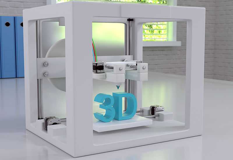
Linear motor 3d printer
Science And Engineering - Linear Motor Based 3D Printer
I have found very little information on existing 3D printers using linear motors. At least in principle this seems like a good idea, and there is some discussion here:
http://forums.reprap.org/read.php?2,513603
and one working unit here:
http://www.everythingbends.com/search/label/LinearFDM
There are advantages that make me want to build a 3D printer using linear motor based linear actuators:
- Linear motors can run very fast
- The actuators I consider are very stiff, both electronically and mechanically
- They are servo motors, so I can directly measure under and overshoot
- The encoders go down into the nanometer regime
I did check that last fact already by using the laser interferometer to check on some moves I did with a Parker MX 80 like this one:
A quick test with some moves over a few cm yielded at least 150 nm positioning accuracy and repeatability - good enough for what I have in mind.
The base for the printer will be an optical breadboard. These are flat, stiff, nicely anodized and have a lot of mounting holes from the get-go.
For the vertical axis, I found some linear actuators on eBay that use ball screws, stepper motors with encoders and can mount vertically. I will use two of these.
For the X axis, I found a Parker I-Force Ironless 110 linear motor mounted on a linear guide rail together with a Renishaw RGh34 encoder. The part number on the encoder is RGh34 X15F00A
That implies a 1um step size.
I made some adapter pieces that allow me to mount the X actuator on the Z actuators:
Putting these pieces together looks like this:
The linear encoder in the Parker MX80L is a Renishaw RGh34B00Z01A
This implies a 1Vpp SinCos analog signal. Often external interpolator boxes are used to turn that into a digital encoder signal, but the type of motor drive I chose can use these signals directly.
I bought some IONI drives from Granite Devices when they were introduced in a Indiegogo campaign.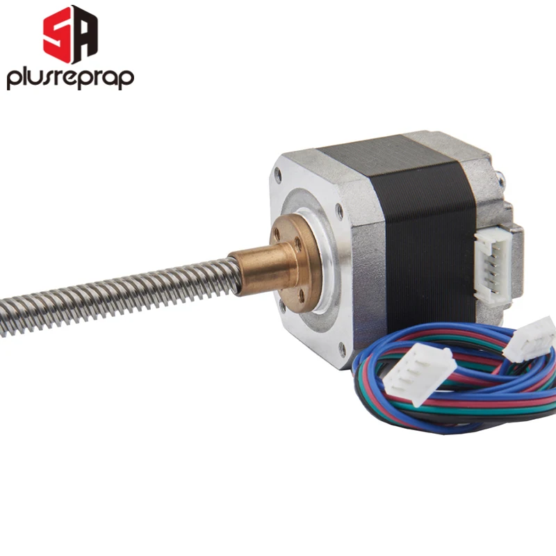 They can do 16, 64 or 256 times interpolation of the SinCos signal. The scale period is 20 um, so that should be 1.25, 0.3125, or 0.078125 um steps. I don't think this is in quadrature yet, so actual positional resolution may be 4 times that. We'll see.
https://granitedevices.com/store/ionicube-4-axis-ioni-motherboard.html
These same drives can also use digital encoders, which is what is on the X axis, so that is very convenient here. With the IONI servo drives themselves, I also got an IONICube 4x, which allows me to interface them to the motors and feedback and control devices.
The IONICube takes 24V to drive it's logic components and allows motor drive voltages from 5-52 V.
I decided on a DuetWifi board to act as printer controller.
The Duet can run on a 12-24V input. This could be quite convenient. I can run the heatbed, nozzle heater, Duet and IONICube, and motors on 24V. If I don't like the performance of the linear motors, I can increase the voltage for those up to 52V.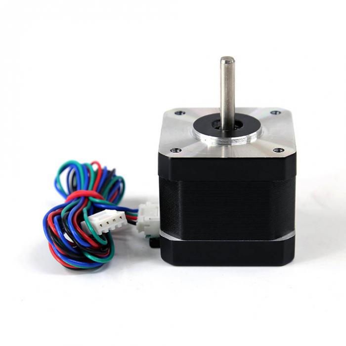 However, the heatbed I chose is made for 12V, and so the PWM controller of the Duet has to be carefully set to not heat it up too fast. I will probably add a fuse to be safe. The Duet documentation here:
https://duet3d.com/wiki/Tuning_the_heater_temperature_control
states that the PWM can be limited to a maximum duty cycle. So I will use a combination of that and a fuse.
So, to start, I put all the major components on a literal breadboard:
From there I proceeded to update the firmware on the IONI drives. They still had the initial firmware on them...
Next, the linear motors need to be connected to the IONICube and the drives need to be configured.
The pinout of the RGh34B in the Parker stage is:
The Parker stage has 3 cables coming out of it.
This seems like a straight forward connector swap, since the feedback connector for the IONICube is also a 15 pin one.
An important note on shielding: Signal ground and earth ground should not be connected together.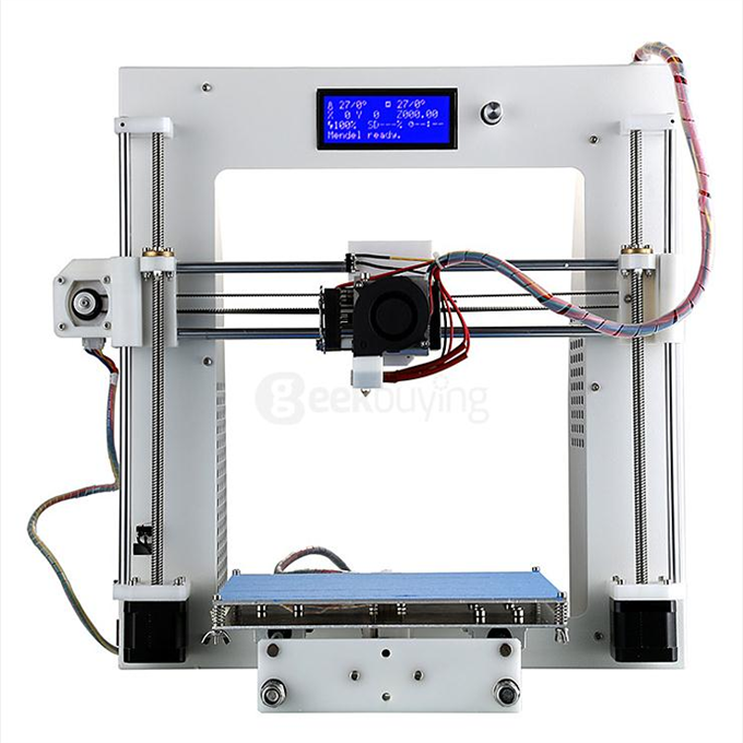 The proper way to connect the shield on an encoder cable is as explained here:
If there is only one shield, then that needs to be connected to earth ground.
The feedback pinout on the IONICube is:
https://granitedevices.com/wiki/IONICUBE_connectors_and_pinouts
Pin #
Shell
1
2
3
4
5
6
7
8
9
10
11
12
13
14
15
Pin layout
Pin name
GND
HALL_W
HALL_V
HALL_U
GND
B-
B+
A-
A+
5V_OUT
GND
GPI3
GPI2
GPI1
C-
C+
Electrical type (in most feedback device modes)
Alternate electrical type (in some feedback device modes, i.e. SinCos encoder)
Connection with various feedback devices
Feedback cable shield
Hall sensor input, phase W
Hall sensor input, phase V
Hall sensor input, phase U
Quadrature encoder (B channel)/SinCos/serial encoder/resolver input
Quadrature encoder (A channel)/SinCos/serial encoder/resolver input
Encoder power supply
Connect normally closed (NC) limit switch between this pin and GND pin
Connect normally closed (NC) limit switch between this pin and GND pin
Connect normally closed (NC) limit switch between this pin and GND pin
Quadrature encoder index channel (Z channel)/serial encoder input
Earth/case
Digital input W
Digital input V
Digital input U
Encoder supply ground
Differential input B-
Differential input B+
Differential input A-
Differential input A+
SinCos input B-
SinCos input B+
SinCos input A-
SinCos input A+
Encoder supply 5V output
Encoder supply ground
Axis negative direction end limit switch (optional)
Axis positive direction end limit switch (optional)
Axis home switch switch (optional)
Differential input C-
Differential input C+
Female D-sub 15 connector as it appears from outside of drive.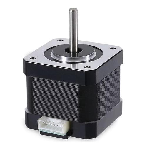 Note: counterpart (male) connector has mirrored pin layout if viewed from pin side, and same layout if viewed from soldering side.
So here is the parker cable assignment for the first test:
The limit switches come, as described above, from a second cable. The IONICube supports hard homing, so I am not sure right now whether I want to use the limit switches or not.
And the motor pinout on the IONICube is:
And the example for 3 phase motors is given as:
To check the encoder parameters, I set the interpolation to 256x and moved the actuator its whole range of about 154 mm. The reading was about 7840000. 154000/7840000 comes out to about 0.0196 um.
Above, I estimated 0.078125 um steps at 256x interpolation of the 20um scale. It looks like I get another 4x from quadrature interpolation as 0.078125/4 = 0.01953125.
This runs at a top speed of just 1000 mm/s, but only when doing full range moves:
I did get a standard Prusa style bracket to hold the heated build plate and mounted that on the MX80L. Then, after some tuning here is what that works like. The moves are a bit more of what one would expect for 3D printing. The top speed of the fastest moves here is about 500 mm/s:
Analysis of tracking error of these moves shows that with the current tuning parameters the setup can hold position to within 4000 counts. That is equivalent to 0.01953125 * 4000 = 78.125 um worst case at maximum acceleration allowed by the servo controller settings. Lower accelerations provide higher accuracy, of course.
This is good enough to move on to the next axis.
The pinout of the RGh34 X15F00A is:
The 'A' at the end of the part number indicates that this sensor is set up for a reference mark, rather than a limit switch.
The motor itself has the following pinout:
Both, the motor and the encoder use connectors that fit onto a 10 pin IDC header.
So in the case of the encoder:
And for the motor:
But the IONI wants the encoder and hall signals on the same 15 pin connector:
Since I already have designed ICD to RJ45 adapter board for HEDL encoders, I decided to use those at for prototyping the servo:
The standard board would assign the RGH encoder signals onto the RJ45 pins like this:
which is not going to work. But the board has been designed to be easy to cut and jumper, so the pins will be reassigned:
The second adapter board connects to the motor. I have some concern about the ethernet cable being able to power the motor, but it's worth trying. Ethernet cables of category 5 should be between 22 and 24 AWG thickness, according to:
https://en.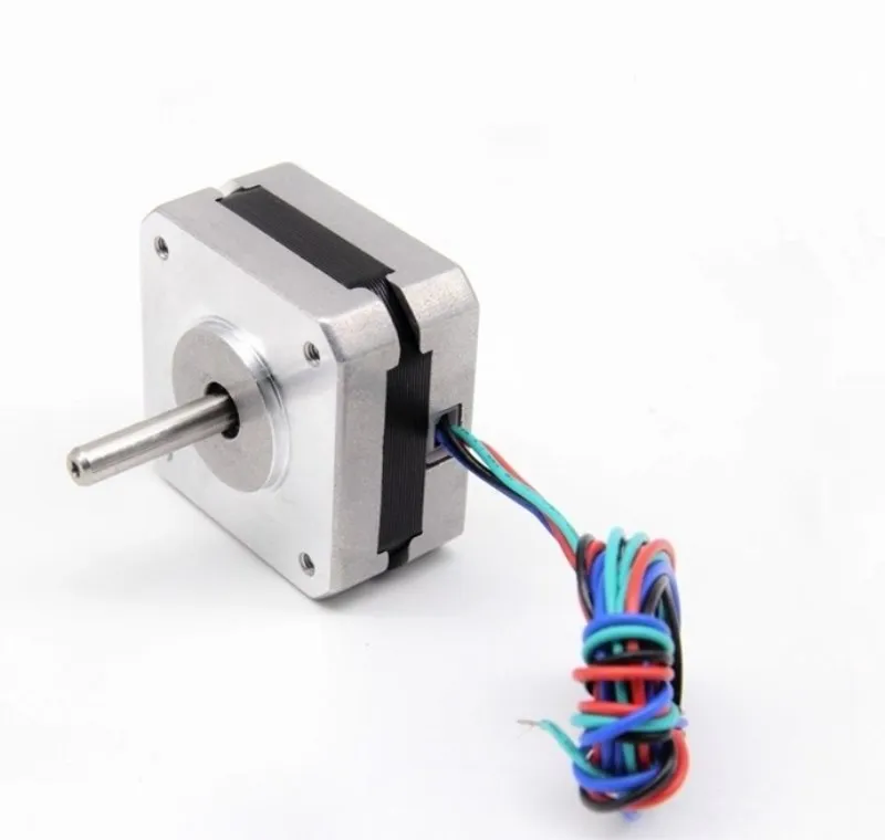 wikipedia.org/wiki/Category_5_cable
It looks like Cat5 and Cat6 cables are readily available in 22 AWG. The rated current for a conductor like this is shown here:
http://cablesondemandblog.com/wordpress1/category/cable-amps-current/
So depending on cooling the 22AWG ethernet cable should be good for 1-7A, and 24 AWG about half that. I suppose I can almost double that by doubling up on the conductors in a cable.
Unaltered, it maps the pins like this:
So it looks like it's sufficient to reroute pins 5 and 6:
Sanity checks: The encoder is supposed to resolve 1um steps. The electrical cycle length for the motor is specified as 60.96 mm. So I moved the motor up to a particular hall transition, marked the position, and then moved the motor until that transition repeated. The distance moved should match the electrical cycle length - and it does. The encoder count moved by 60150, which is very close the the theoretical 60960.
This works pretty well, as can be seen here:
However, there are some situations where the IONI is incable of holding any accuracy at all. When setting the maximum speed to 1000 mm/sec, most moves are problematic in one way or another depending on the tuning parameters. At 500 mm/sec maximum speed most moves can be made to have an acceptable tracking error, but there are some pathological cases where a resonance appears, like here:
There is a tracking error of about +-30000 (60mm) counts for a move of about 50000 counts (50 mm). This is pretty unacceptable.
I think I will have to look into adding friction to the linear rail to address this. Or maybe replacing the IONI with a better drive will solve the problem. Of course, it is also the case that usually there is a tracking error limit, so that the drive would set an error and disable itself with errors like that. However, most 3D printers run open loop anyway and I am more interested in what my tracking errors are like over time than in canceling the print.
Another problem is that these drives are very noisy and generate a constant hiss even when idle. I have 2 more IONI drives in a Roland PNC retrofit mill. There, too, the drives are very noisy. So this is a good opportunity to test the Granite Devices support. First, I sent a message to their online forum here:
https://community.granitedevices.com/t/hissing-noise-from-motor/923/3
I got some feedback within a day, which was not helpful. But since they can't know if I know anything about servo tuning at all, it was reasonable advice. Then I replied that their advice was not helping the situation. Then.....crickets.
After 20 more days of no reply, I gave up on the online forum and sent out a formal tech support request through their website, adding a short video with the noise.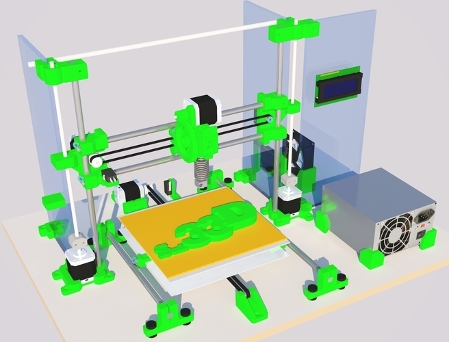
On Feb 2 I sent this:
"Hi, I am using IONI drives for linear motors. 2 of them are in a milling machine and 2 are in a 3D printer. They are noisy. There is a constant hissing. I have been building CNC machines for years, so I have experience tuning drives, but I don't claim to be an expert. Messing with the torque bandwidth is ineffective.
I am attaching a video with the noise. There is no way to convey the correct loudness of course, but you can hear the nature of the noise."
Anyway, how can I remove the hissing?"
On Feb 5 I got this reply:
"Hi Jan
What revision of the IONI card are you using? The first revision had some cross-talk noise that was somewhat reduced in the second revision.
Also, if the tuning is very tight, it also causes some hissing."
So on the same day I replied:
"I tried very tight and very very loose tuning. Noise still very audible.
All 5 of my IONI drives are from the original Indiegogo campaign."
Then, within a few hours, I got the following reply:
"What firmware version are you using? We implemented at one point a noise reducing filter when TBW < 680 Hz.
Also, you can lower the resistance and inductance values, although that would affect the tuning."
To which I replied:
"I am using the latest firmware.
The TBW only ever changes the pitch of the noise, but not the loudness, though I can clearly tell when I go below 680 Hz by a lowering of the pitch.
The resistance and inductance values have a very positive impact. I lowered the resistance from the ~7.5
ohm to 5 and the inductance from ~2.2 mH to 1. It did noticeably quieter, but I did not want to push these values lower than that without knowing what I am doing.
I certainly don't mind retuning.
Am I endangering the motor or the drive by lowering these values? How am I affecting drive performance when lowering the resistance? The inductance?"
11 days later I sent them a reminder:
"
Hi, just a friendly reminder about the outstanding questions.
Thank you."
Then, 6 days after that, I noticed that the granite devices support online ticket tracker does not show my replies, so I re-submited the first reply there.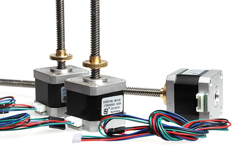 Maybe they can send emails to me but not get any back?
They then came back with information on the forum that was pertinent:
https://community.granitedevices.com/t/hissing-noise-from-motor/923
I was able to get the drive quite quiet by putting the resistance and inductance values to ~ 1/10 of the real values. I originally thought that by measuring these values or putting in the manufacturers’ published values, that was the best for any use case. I think most others would think this too. I now consider these values to be just another tuning parameter, and I think they should be documented as such. Since there is no deadband filter, you lose performance if you don’t like hunting. The X axis was hunting ± 1 count (1 micron) and produced a quite annoying squeal. I reduced the gains to get rid of it, but of course the motor performance is lower than it could be.
Some small things that I hope GraniteDevices addresses in a future release:
- the tracking error graph on the servo scope would be more useful to me if it showed distance units on the right hand side.
 This way I can tell what the worst case tracking error is without taking out the calculator.
 - I sure wish there were some frequency analysis available in the servo scope and maybe a bode plot together with one or more IIR filters in the IONI. I had to use my phone with an audio spectrum analyzer to get any idea at what frequency a filter should be set up. Of course, that only works if you manage to find a pathological case manually and get it to persist long enough to get a reading…
Also, the tech support is kind of hit and miss. Sometimes you get a great answer quickly. Sometimes you have to wait a number of days and still get an answer that is not very helpful. I actually had already given up hope on the support and ordered a Parker Compax 3 drive to solve the noise problem. Maybe I will still make the substitution to compare performance. My experience with Dynomotion has been way better. They usually come back with pertinent questions or very helpful suggestions within 24 hours. In any case, the X axis is now very quiet.
The Z axis actuators are driven by Vexta PK245-01BA stepper motors, and the Duet Wifi can drive them independently to correct for vertical misalignment of the build plate:
https://duet3d.com/wiki/Bed_levelling_using_multiple_independent_Z_motors
They came with some connector that I did not have a match for. And the X-Y stage I used for the PNC-300 retrofit came with cables using DB9 connectors, so I am going to use them for this project.
The motors have 6 leads, connected like this:
So, I am using the following pinout:
With the plan of using only 1/6 and 5/9.
To mount the connectors on the z axes I fused a 3D model of the bottom of a standard DB9 shell with a ring that fits on the existing mounting holes.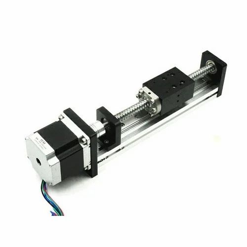 Then I just screw the top of a standard DB9 shell to that and have the connector firmly mounted.
Since I don't plan to use the stepper drivers for the X and Y axes on the Duet Wifi, I am using them to drive the dual Z axis. Instead, I am going to use the step/direction signals on the expansion header and forward those to the servo drives. The Z axis can then be configured by changing the config.g file with the following lines:
M584 X8 Y9 Z0:1 E3 ; Apply custom drive mapping
M350 X16 Y16 Z128 E16 I1 ; Configure microstepping with interpolation
M92 X80 Y80 Z5120 E420 ; Set steps per mm
And that allows me to jog the z axis:
The stepper motors here are noisier than I had hoped, so I tried to change the connections to
2/6 and 4/9. The hissing is less, but still more than I like. I may replace the stepper driver with a servo driver at a later time...
Homing:
The IONIcube has two connectors, X4 and X5, that will be used to connect to the DuetWifi.
X4:
And the DuetWifi Expansion connector has the following pinout:
The signal levels on the DuetWifi are 3.3V whereas on the IONI they are 5V. This requires some care.
In all, there are 8 signals that need some sort of level shifting:
- The 2 signals coming from the DuetWifi to the IONI to start homing
- The 2 signals coming from the DuetWifi to the IONI to take a step
- The 2 signals coming from the DuetWifi to the IONI to select direction
- The 2 signals coming from the IONI to the DuetWifi to signal that homing is done.
After rummaging through the parts bin, I decided to use a IL715 signal isolator as a level shifter. This also helps separate motor noise from the boards.
Three signals require a GPIO pin on the DuetWifi:
Before the IONI servo drive operates, an enable signal has to be set high.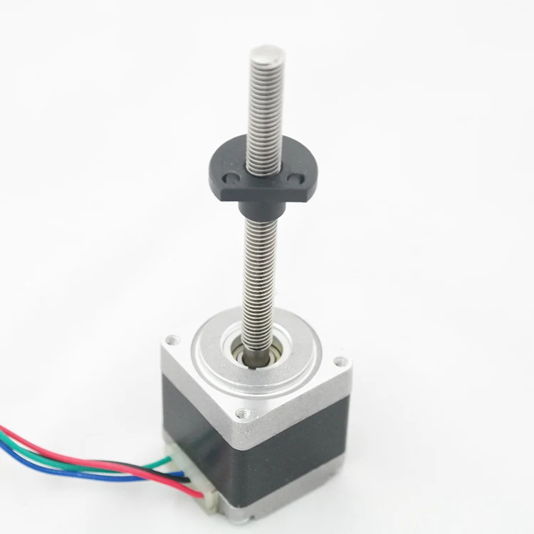 DuetWifi Pin 9 is labeled E3_STOP and has logical pin name 61. This will be the enable signal.
Pin 19 is labeled E5_STOP and has logical pin name 63. This will be the homing signal for the X axis.
Pin 14 is labeled E4_STOP and has logical pin name 62. This will be the homing signal for the Y axis.
The remaining pins can be used without manually toggling GPIOs. The connection map between the DuetWifi and IONI is as follows:
I am using a Bondtech BMG extruder, to use in a bowden configuration. This then feeds the left side of the chimera which is put in a custom mount. I also made a mount for a IR height sensor.
All this then allows for a first test print:
But of course, there is still a lot of cleanup work to be done:
Linear motor stages for the printing industry
Skip to contentLinear motor stages for the printing industrySinadrives2021-04-28T11:23:52+00:00
Linear units with linear motor for the 2D and 3D printing industry
The printing industry is nowadays going through one of its best moments. In the last ten years, thanks to the strong push of 2D and 3D printing technology, a new era in large format printing has begun, in which many types of materials and means are available. Printing on textiles, paper, glass, glass, wood or plastic no longer has secrets. For the machinery manufacturers, the technologies are well-known and established for 2D printing (with regular ink or latex) or for 3D printing with polymers or metal. The industry feels the urge to produce more competitive machines which reduce costs and increase precision.
Improvements in dynamics and precision are important factors in the decision for a linear motor unit. Thus, the end customer receives an advanced solution which is adapted to their needs, with higher repeatability and faster speeds. At SINADRIVES we respond to these challenges with our most advanced solutions based on Direct Drive technology, which result in log-term competitive advantages.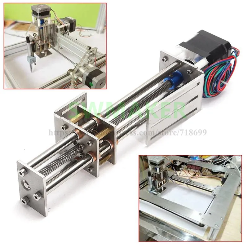
Using linear stages with linear motor in the 2D and 3D printing industries
Since the inkjet printing technology has become a mainstream solution, many young companies have emerged that have seized the opportunity to be first in the new printing technologies. These are young OEMs, with a growth potential and a capacity for innovation. This is is an obvious step, as these companies accept linear motor technology as a regular one and that is why, today, 80% of the printers on the market are powered by linear motor technology. The use of linear units with linear motor in the printing sector is very popular due to the many advantages that this technology offers to the manufacturer.
The main advantages of using linear motor stages
Some of the advantages that this technology brings to printing machinery are:
– An improved print quality
– A higher productivity
– Improvements in dynamics: speed, acceleration and precision
– Reduced maintenance: less maintenance stops and more availability
Compatibility with PCs and control electronics
In most cases, the printers are controlled by a central PC responsible for coordinating the functionality of the print head / heads with the movement of the axes.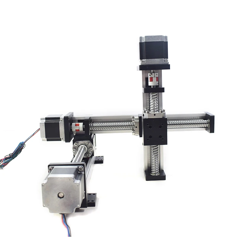 The linear stages with linear motor are compatible with the most used and accepted servo driver brands in the industry. Thanks to this, the implementation of sophisticated controls is easy and fast. The SINADRIVES team is happy to help carrying out the commissioning of our linear units.
Additionally, we can point to a very low Cogging value of our linear units, which has a positive influence on getting constant speeds while printing.
Typical applications in the 2D and 3D printing industry using linear motor units
Any application performed by a linear or rotary motion can be performed using a linear drive with direct drive technology:
– Head movement in longitudinal direction (main printing movement)
– Head adjustment in vertical position
– Movement of the object which is being printed
– Applications of pad printing, screen printing and digital printing
If in doubt, please contact us.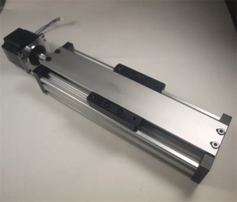 Through a free study of your application, we will inform you about the advantages a linear motor solution can provide. Our technical department is happy to assist you to carry out the relevant printing tests.
Future trends and projects in the printing sector
Precision demands are increasing in 3D technology. We are not only talking about positioning accuracy or repeatability, but also about absolute geometric precision, like flatness or parallelism. These factors are decisive when it comes to getting highly precise parts with high geometric tolerances. The SINADRIVES team is up to these challenges with all its technical competence and experience. We assist clients in integrating linear drives with linear motor into their systems. Take advantage of our experience and know-how!
Toggle Sliding Bar Area
Search
Search for:
Get Social
Page load linkGo to Top
Design of 3D printer
FDM technology is the most widespread among lovers of spatial modeling.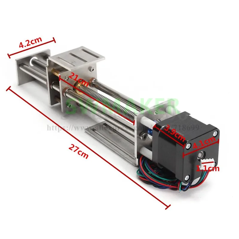 Different models of printers may be used, but the designs of 3D printers from any manufacturer have much in common. This allows you to highlight the characteristic structural features of such equipment.
- 3D printer design
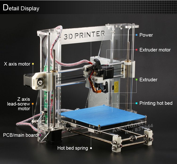
At its core, a 3D printer is a small CNC machine. Its main parts are assembled on a frame placed in the body. The control of actuators is impossible without an intermediate block - the control controller, which issues commands understandable for the device with a special G-code. You can highlight the main structural elements that ensure the operation of the printer.
Stepper motor
The working body (printing head) for the formation of a spatial detail must move along three axes (X, Y, Z) in a certain sequence at a given distance. Stepper motors provide uniform and precise movement. There must be at least 3 (one for each axis). The most commonly used full step motors are 1.8° (200 steps per revolution).
Half-step and micro-step motors can be installed in machines with increased movement accuracy.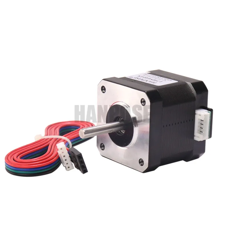 The first option provides for a move of 0.9°, i.e. 400 steps per full turn. In microstepping motors, each full step can be divided into 4, 8 or 16, and a full revolution contains up to 3200 microsteps.
Standard stepper motors are rated for 4V, 8V, or 12V power supplies. The most common NEMA 17 motors are 1.7" x 1.7" (43.2 x 43.2 mm). Smaller motors (eg NEMA 14) may also be used. To convert the rotational motion of the rotor into translational, a system of pulleys driven by toothed belts or threaded shafts is used.
Extruder
The working body of the printer is an extruder, or print head. Its task is to melt the plastic and feed it through the nozzle into the working area. The extruder consists directly of a thermal head and a material feed mechanism. The starting material is used in the form of a filament with a diameter of 1.75 or 3 mm. For its dosed supply, a stepper motor and a system of shafts and gears are usually installed.
The filament is guided into an aluminum head with a heater that heats the mass in the range from 160 to 280-300 °C, depending on the plastic used. The highest temperature is maintained near the nozzle through which the melt is fed for printing. The size of the nozzle opening can be from 0.2 to 0.5 mm. The possibility of full control of the heating mode is provided by fans and built-in "thermal barriers" in the form of gaskets made of heat-resistant polymers with low thermal conductivity (Teflon, fluoroplastic, etc.).
Important! Typically, the printer comes with one print head. In some models, 2 extruders are installed to supply different materials.
Print Bed
Printing parts on the printer requires a work area, i.e. a print bed (surface) or desktop. It is characterized by such important nuances:
- The size of the platform determines the maximum dimensions of the formed part. Most often, the area of \u200b\u200bthe working area is 140–220 cm 2 .
- Heating For a number of polymers (for example, ABS) preheating of the working surface is required.
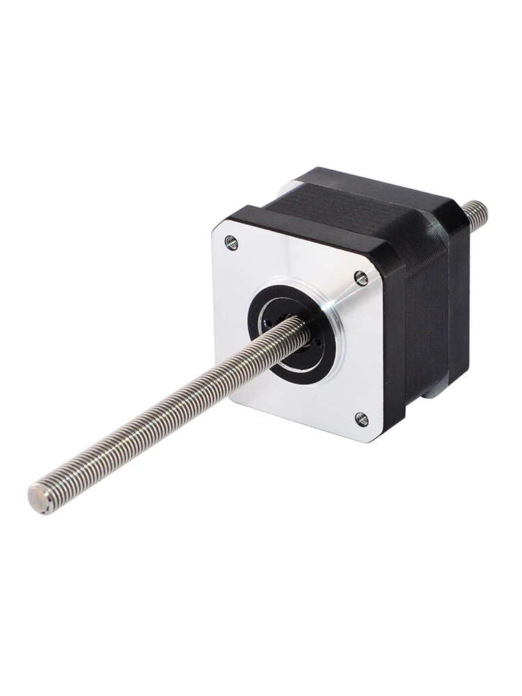 With this in mind, printers are produced without heating the desktop (for PLA) and universal installations for any plastic. In the latter case, the platform is equipped with a sufficiently powerful heater capable of bringing the temperature of its surface above 100 °C.
 - Work table available in aluminum or glass. These materials provide uniform heating and smoothness.
- To increase the adhesion of the polymer to the platform, its surface is covered with a special film. The most common found: nylon, polyamides, blue tape (Scotch Blue Tape).
Important! In addition to these features, the table adjustment system is the most important element. It ensures accurate horizontal alignment of the surface during calibration.
Linear motor
The main drive, or linear motor, determines the print speed and productivity of the equipment. The supply of plastic depends on it, as well as the movement of the part.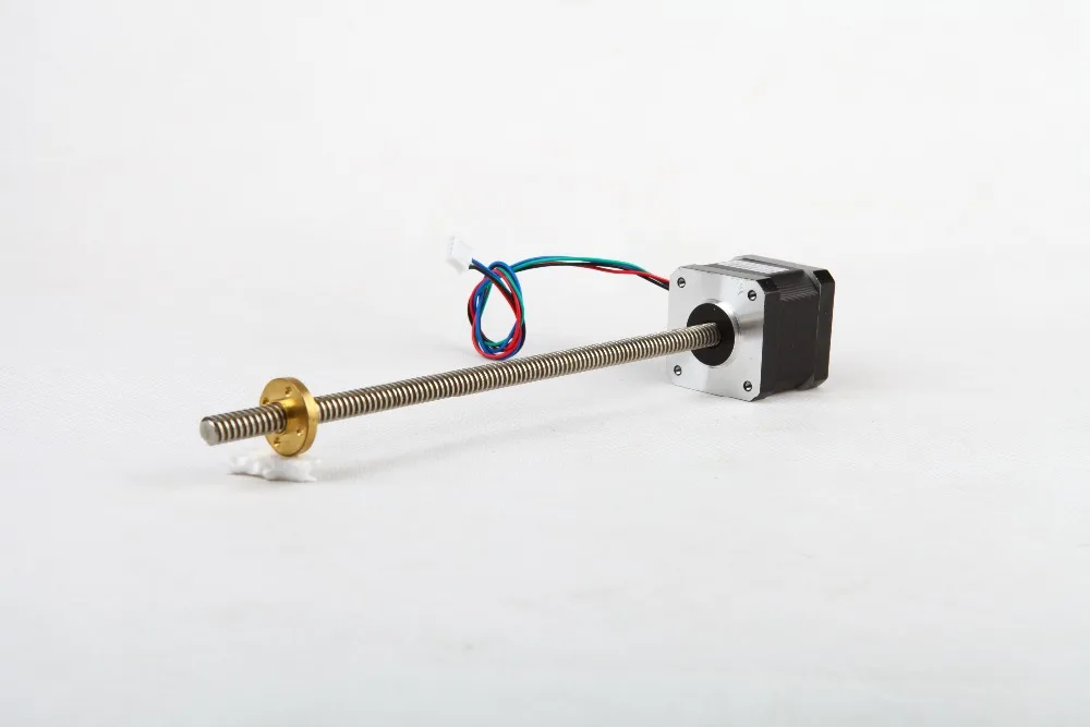 For the drive, high-precision rods are used for each axis. Movable plastic or bronze bushings (ball bearings) are installed on them. With the help of the main drive, the initial coordinates are set when setting up the device and performing calibration.
Sensors
An obligatory element for controlling the operation of a 3D printer is end sensors, or clamps. They are designed to ensure the retention of the movements of the working body within the working area. The most commonly used are simple end switches of the EndStop type. They should warn about the approach of the head to the boundaries of the field. They are also needed when setting the origin of coordinates along all axes. In simple models, the simplest push-type sensors are used as clamps. Optical devices are used for more precise control.
Frame
All parts of the printer are attached to the frame. It must have sufficient strength, and the attachment points must not relax during the vibration that occurs during the operation of the engines.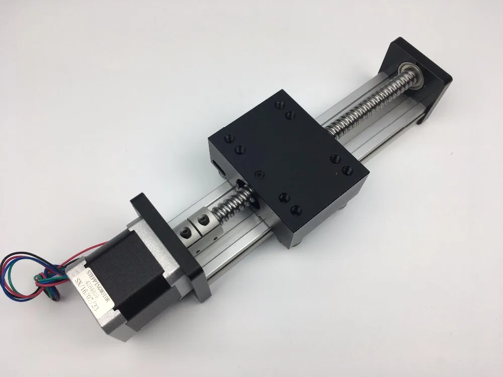 High-strength polymer is used as the frame material, but the greatest strength is achieved when using an aluminum profile. Fastening of parts is carried out with the help of screws and nuts, couplings and clamps. In homemade designs, plywood is often used.
The design of 3D printers is simple enough that you can assemble them yourself. In modern models, manufacturers add elements of quality control, which somewhat complicates the structure and leads to higher prices. In general, when manufacturing a printer, it is important to ensure assembly accuracy and the possibility of correct calibration along all axes of movement, which determines its high-quality and reliable operation.
- May 17, 2021
- 983
Get expert advice
cylindrical linear motor / Habr
many intermediate parts, which complicates the design and reduces reliability. However, there is an alternative, and that is what we will talk about in this article.
Scientific and technological progress, covering one sphere of human life after another, gradually modified the way of transmitting movement from the electric motor. If on the machines of the beginning of the last century there was one electric motor for all and the movement from it was transmitted along the shaft through the entire workshop, from which individual machines took the necessary torque using a belt drive, then with the acceleration of progress, the engine first moved as close as possible to a specific machine, and then completely switched to each machine.
Transmission links from the engine to the machine also underwent changes. For example, ball screws have become widespread.
Source: 3d-diy.ru
Moreover, ball screws have only relatively recently become widely available, their production technology has been sufficiently developed, and the cost has become affordable for a wide range of consumers. In turn, a variety of gears have always been relatively affordable and widely used in various motion transmission schemes.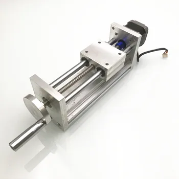 Gears have always had one negative side - quite a lot of noise in operation and physical wear when the teeth rub against each other. Of course, this can be somewhat leveled by careful lubrication, however, it attracts dust, specks, and contaminates the working gearbox (especially if this gearbox is installed on a metalworking machine).
Therefore, engineering thought was looking for some other solutions that would allow getting rid of intermediate links. And such a solution was found - a linear electric motor!
A linear motor is an electric motor in which the stator and rotor are "turned" so that instead of generating torque (rotation) it produces a linear force along its entire length.
Author: Schnibbi678 — Own work, CC BY-SA 3.0, Source
However, linear motors are not necessarily straight:
Author: Lutex (talk) - Own work, CC BY-SA 3.0, Retrieved
It is characteristic that the active part of a linear motor has ends, while more traditional motors are arranged in a continuous circuit.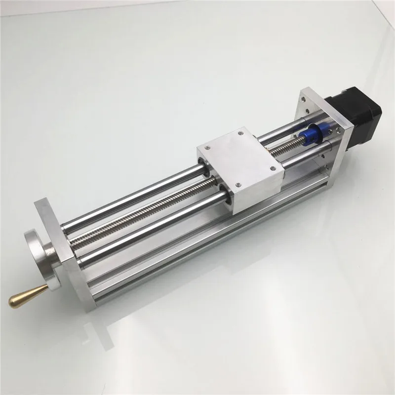
Many designs of linear motors have been proposed, which can be divided into two main categories:
- low acceleration linear motors;
- high acceleration linear motors.
Low acceleration linear motors are suitable for maglev trains and other ground vehicles. Motors with low acceleration, high speed and high power are usually linear synchronous motors. (LSM) with an active winding on one side of the air gap and an array of alternating pole magnets on the other side.
High acceleration linear motors are usually quite short and designed to accelerate an object to a very high speed, e.g. railgun:
High acceleration linear motors were offered for a number of applications. They were considered for use as weapons, since modern armor-piercing ammunition, as a rule, consists of small projectiles with very high kinetic energy, for which such engines are suitable. Many amusement park rollercoasters now use linear induction motors to drive the train at high speed.
They are typically of a linear AC induction motor (LIM) design with an active three-phase winding on one side of the air gap and a passive conductor plate on the other side. However, a DC railgun with a unipolar linear motor is another high acceleration linear motor design.
High speed linear motors are difficult to design for a number of reasons. They require large amounts of energy in very short periods of time. One rocket launcher design requires 300 GJ for each launch in less than a second.
Conventional electrical generators are not designed for this load, but short-term energy storage methods can be used. Capacitors are bulky and expensive, but can quickly supply large amounts of power. Unipolar generators can be used to convert the flywheel's kinetic energy into electrical energy very quickly.
High acceleration linear motors also require very strong magnetic fields and the magnetic fields are often too strong for superconductors to be used. However, with careful design, this should not be a major problem.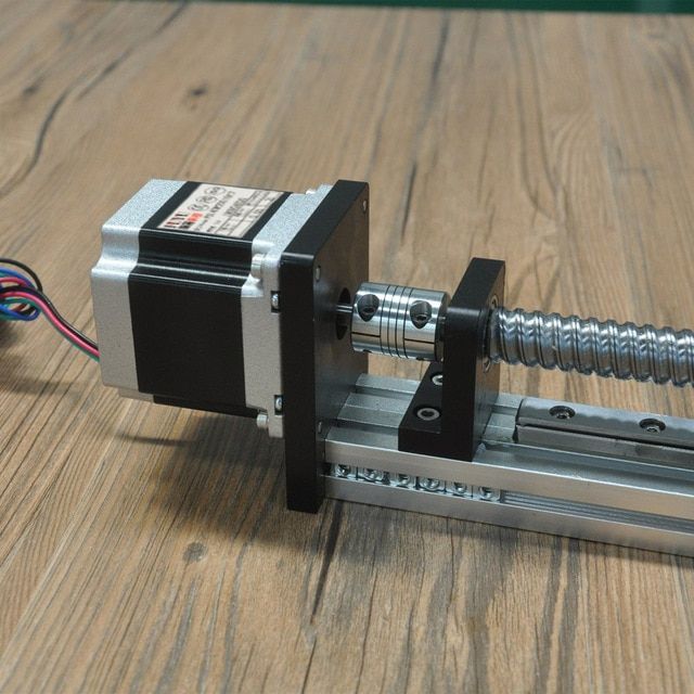
At the moment, the use of linear electric motors has not yet been fully developed, and therefore their manufacturing technology and cost leaves much to be desired. However, the use of a linear motor makes it possible to implement such tempting options as high speed movement (up to 1.8 m/s and more!), with virtually no mechanical wear:
However, not all motors are so good, for example, flat linear motors (the diagram of which is shown a little above).
In addition to the complexity of manufacturing, they are characterized by increased heating, which is caused by Foucault eddy currents, which is further aggravated by the limited ability to cool the engine, because, as a rule, the working table of the processing machine is mounted on top of them. Since many industrial machines, especially metalworking ones, have increased requirements for rigidity and accuracy of the structure (to ensure the required machining accuracy), such engines introduce distortions into operation due to thermal expansion of the structure due to heating in the process, and heating can even reach 100 degrees Celsius!
Cylindrical linear motors are an alternative to flat linear motors.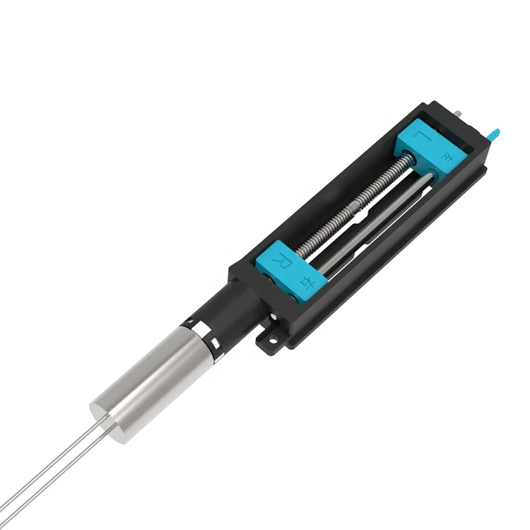 They are arranged as follows: a cylindrical winding is located around a core formed from magnets. That is, the coil can move along this core.
In contrast to a flat motor, a linear motor is cooled quite effectively and therefore does not require complex and problematic designs for cooling, and since it does not have a core, there is no potential source of heat under the influence of eddy currents.
Due to the absence of a core in the design of a cylindrical motor, it can operate very smoothly, without speed jumps:
In other words, ultra-precision equipment can be built on the basis of linear electric motors.
In addition, due to the symmetrical design, there is a more efficient use of magnetic flux, which allows you to achieve greater efficiency due to the use of 2 times less rare earth magnets.
As mentioned above, the wear of this type of engine during operation is very insignificant, since there is practically no direct physical contact between the coil and the cylinder-axle during operation.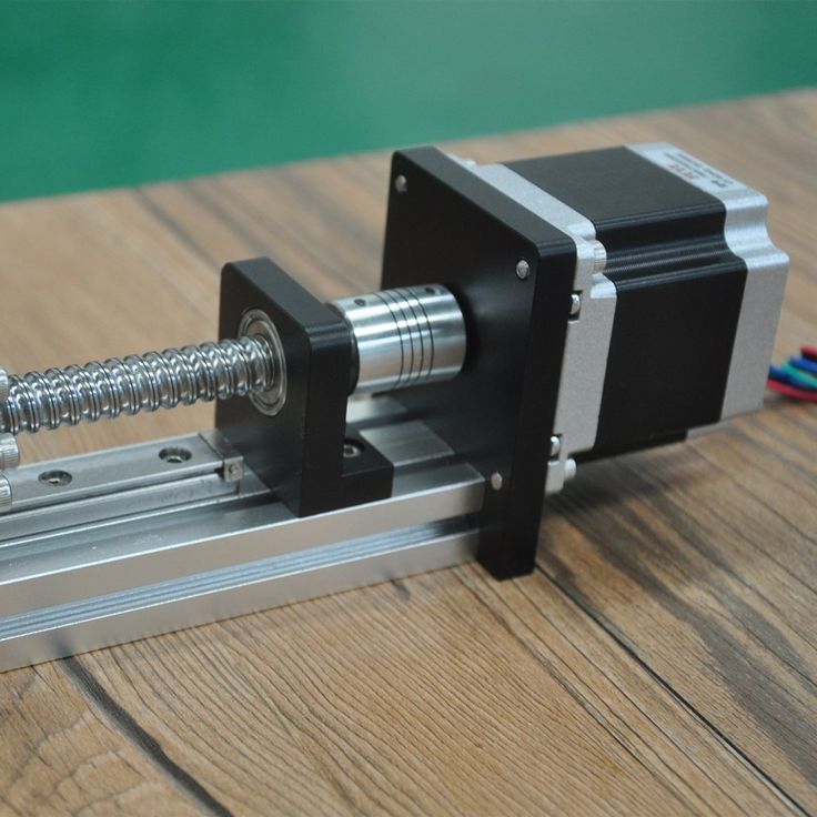
The principle on which the operation of linear motors is based is the manifestation of the force that acts on a current-carrying conductor in a magnetic field, that is, on the basis of Ampère's law (based on which we can say that the maximum force that a motor can develop is the product of the force current in the windings by the vector product of the magnetic induction of the field and the vector of the length of the wire in the windings).
in fact, it only slows down the movement. But this only applies to a flat engine! In contrast, the device of a cylindrical linear motor allows current to flow almost along the entire length of the windings at an optimal angle of 90 degrees.
For those who want to try to build a similar motor for their own needs - I am attaching below a link to the thesis "Design and Assembly of a Precision Tubular Linear Motor and Controller" (Design and Construction of a Precision Tubular Linear Motor and Controller, - Bryan Craig Murphy), where the theoretical basis of such an engine is analyzed in sufficient detail: Link to the thesis.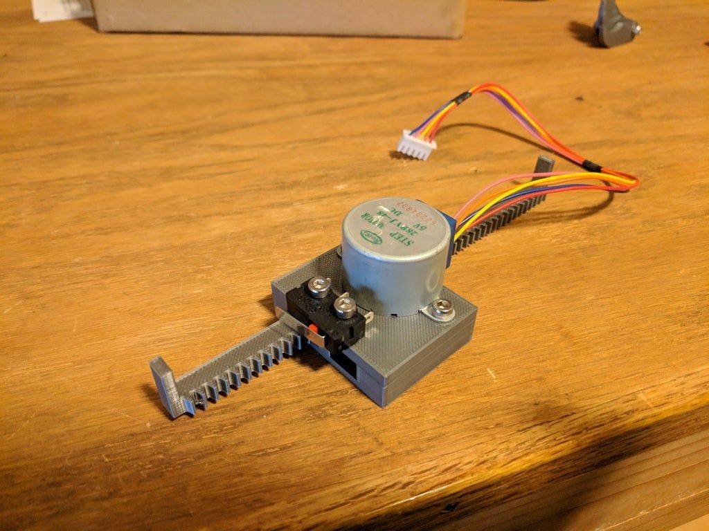
According to paragraph 1.4 of this thesis "Proposed Design" (Proposed Design), the author considers a device in which the rod moves, and the coil unit remains stationary (although this is not the point, you understand that if you wish, you can move either this or that, or "all at once and a lot" © :-) ): the device consists of an array of magnets inside an array of electromagnetic coils.
The coils are divided into three phases: A, B and C. Each phase has three coils; the center coil of each phase faces in the opposite direction to the two outer coils. Thus, when current passes through the phase of the coils, the center coil will generate a magnetic field equal in magnitude to each of the other coils in that phase, but in the opposite direction.
Image source: Thesis "Design and Construction of a Precision Tubular Linear Motor and Controller, - Bryan Craig Murphy"
As shown in the figure above, the motor uses cylindrical permanent magnets.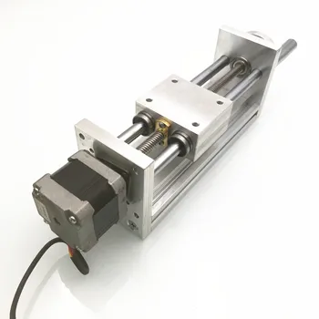 Pairs of magnets are oriented in the same direction and are opposite adjacent pairs of magnets. An aluminum spacer is placed between pairs of opposing magnets to facilitate construction. When current flows through the three phases of the coils, the coils generate forces on the permanent magnets according to the Lorentz force equation.
A self-made design, similar to the one described (only the opposite is true - the coil block moves) is shown here:
In its current state, the motor has a rise time of 55 ms, a settling time of 600 ms, and an overshoot of 65% when entered in 1 cm increments. motors of comparable size, however this design allows smoother positioning without the "cog wheel" effect.
The operation of the factory apparatus, approximately the same design as in this dissertation, is shown in the video below:
To sum it up, the widespread use of linear motors is just beginning its life, and everyone can try to build their own design.