3D printing animation gif
Printer Animation designs, themes, templates and downloadable graphic elements on Dribbble
-
View Mobile App for 3d Printer Animation
Mobile App for 3d Printer Animation
-
View Mobile App for 3d Printer
Mobile App for 3d Printer
-
View 3D Printing App
3D Printing App
-
View Fax.
plus logo animation
Fax.plus logo animation
-
View Printer
Printer
-
View Amazon Prime 3D Food Printer
Amazon Prime 3D Food Printer
-
View Purple Spots
Purple Spots
-
View Print Together
Print Together
-
View Empty State Animations
Empty State Animations
-
View Icons (part1)
Icons (part1)
-
View Love printer
Love printer
-
View Print.
 Design. Animate.
 Print. Design. Animate.
-
View Printing Industry
Printing Industry
-
View Desk Supplies
Desk Supplies
-
View Color Proofing Icon
Color Proofing Icon
-
View Hi, Dribbble!
Hi, Dribbble!
-
View Upload File Screen Interaction
Upload File Screen Interaction
-
View SLA 3D printing
SLA 3D printing
-
View One Dribbble invite to giveaway
One Dribbble invite to giveaway
-
View Tiny Illustrations
Tiny Illustrations
-
View ▶ Animated Icons #1
▶ Animated Icons #1
-
View Daily Mail Printer Action
Daily Mail Printer Action
-
View Printer Assembly
Printer Assembly
-
View Custom Printing Co.

Custom Printing Co.
Sign up to continue or sign in
Loading more…
Convert STL to GIF Animation in Bulk Without Losing 3D System
Many working professionals want to convert STL to GIF. Because they want to use animated files for 3D STL models. If you are one of them, then you can continue reading this blog to know the complete method and reasons.
Many professionals, like civil engineers and architects, know the benefits of GIF. They used STL files for 3D printing, but this file is a simple geometry file format without color, texture or other attributes. The worst part about this file is that it’s not open without CAD programs.
Without wasting your time, we are going to the solution, but first we understand the difference between STL and GIF file formats. Then we convert from 3D printing STL file to GIF.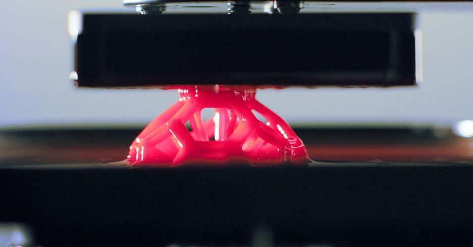 Extra reading is good for knowledge.
Why User Convert STL to GIF?Related Post: How to Convert IFC to PDF for Printing?
There are many benefits to converting STL to GIF. The biggest advantage of GIF is that it can be read on any device rather than an STL file, which is limited to devices that support STL files.
- A GIF (Graphical Interchange Format) is a highly compressed image. It is a more widely used animated file format.
- It will be easier for people to view, understand, and open on any platform like a smartphone, laptop, desktop, etc.
- An animated GIF file can support up to 8 bits per pixel and can contain 256 indexed colors. That’s why it helps them to load faster on Web pages.
- Due to its compact size, extensive colour palette, and animation capabilities, GIF files quickly became a popular picture file format for the early internet and continue to enjoy widespread use to this day.

BitRecover DWG Converter Wizard is an offline software that works without internet connectivity. This tool is also considered an STL to GIF converter. This utility comes with a free demo version that permits you to convert one STL file to GIF by adding a company watermark. Therefore, this is the best option to understand the software process before purchasing the licensed version.
Just click on the Download button and check the software functions. This tool is compatible with all the latest and previous versions of Windows OS, including Windows 11, 10, 8, 7, Vista, Windows Server 2022, 2019, 2016, 2012, 2008, etc.
Benefits of STL to GIF Converter- This software allows you to convert batch 3D STL files to GIF format without losing image quality.
- Another feature is that it creates a separate GIF for each STL file.
- There is no need to install any CAD program while using this tool.
- It maintains all the perpendiculars and vertices during the conversion process.
- You can feel free to save the resulting GIF file at any location. You can even save to an external drive.
- It gives you the facility to convert single or multiple STL files into animated GIF format.
- The 3D System STL to GIF converter supports all STL files that are created by CAD programs.
- Also, this software allows you to convert STL to a Word document without size restrictions.
- Firstly, download and launch the software.
-
Secondly, upload STL files by using the Select Files or Select Folders options, and then click the Next button.
-
After that, all the data will appear on the preview panel. Choose accordingly.
-
Then, click on “Select Saving Option” and choose GIF.

-
Click on the folder icon and save the converted GIF file at the desired location.
Hello, a civil engineer friend of mine sent me STL files, and I want to convert them to GIF animation format for easy opening. But I searched for it on a search engine and then found online STL to GIF converters. For security reasons, I want to use an offline tool for this. My friend suggested me to use BitRecover STL to GIF Animation Converter, and I was shocked. This was a really great solution. BitRecover developers have developed a secure offline tool without file size restrictions.
Time to Say GoodByeIn conclusion, we provide you with the best utility to convert STL to GIF while keeping the original format. So, if you have a 3D System STL file and want to convert it without any CAD program, then you should use the above-mentioned utility for conversion. Still, if you have any queries and doubts, then feel free to contact our support team.
comics, gif animation, video, the best intellectual humor.
brightfuture0
via function.3d
Expand
09/12/202221:27link113.9
Core_of_doom
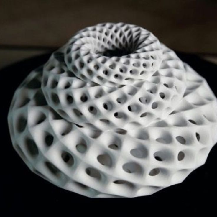
When I was just starting to get acquainted with 3D printing, I thought that an angular figure with traces of underextrusion and a layer of 0.3 mm was the limit of perfection, now in the days of cheap photopolymers I can no longer think like before.
A friend asked me to find a figure of Hermione, I found this model in telegram chats, it is very convenient because it is divided into parts, there are also several NSFW versions for the reactorers. I also liked the model so I have already printed the second one for my collection.
Expand
07/01/2022 2020:34link101.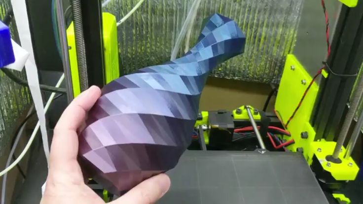 3
3
Erfeakamen
I request the help of fag 3D printers
A friend started printing anything on a printer and says, I can make you, but you need drawings. Share sites where you can see free drawings of all kinds of figures. Thank you all in advance!)Expand
05/31/202212:19link3.0
Meffol
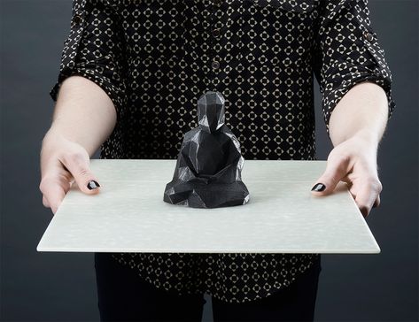
MIT researchers have learned how to grow and print wood on a 3D printer (no)
Researchers have developed a new technology that could one day allow wood products to be 3D printed directly from plant matter. MIT scientists have made a breakthrough in a process that will one day allow us to 3D print wood or grow it directly into the shape of furniture and other items.
Wood is a renewable resource, but we consume it much faster than we replenish it. Deforestation has a serious impact on wildlife and exacerbates the effects of climate change. And since our demand for wood products is unlikely to change anytime soon, our production methods will have to change.
In recent years, researchers have turned to growing wood in the laboratory. Not trees as such, but wood, just as work is currently being done on culturing animal cells to obtain laboratory meat. And now, a team of MIT scientists has demonstrated a new technique to grow wood-like plant material in the lab, making it easy to adjust properties such as weight and strength as needed.
"The idea is that you can grow these plant materials in exactly the form you want, so there's no need for subtractive production, which greatly reduces energy and waste," says Ashley Beckwith, lead author of the study. "There is great potential to scale up this process and grow 3D structures."
The team began by extracting cells from the leaves of a plant known as Zinnia elegans. These cells were then cultured in a liquid medium for two days, after which they were transferred to a thicker gel-like mixture.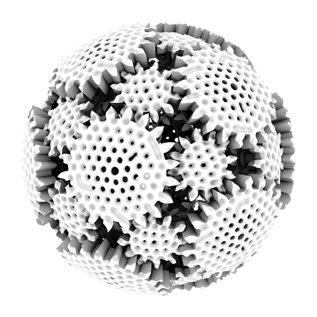 This substance contained nutrients and two types of plant hormones, the level of which could be adjusted to adjust the physical and mechanical properties of the material.
The team then 3D printed this cell gel into a specific shape (just like classical 3D printing of plastic objects). After three months of incubation in complete darkness, the material was dehydrated. As a result, an object was obtained, from the plant mass in its structure resembling wood. In one of the tests, for example, the team formed a tree model from the material.
Diagram showing how plant cells can be grown and 3D printed into individual shapes that differ in strength depending on the concentration of hormonal components
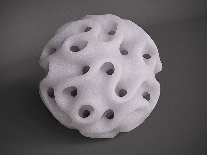
By experimenting with different levels of hormones, the team found that lower concentrations resulted in a less dense material with rounded, open cells. At higher concentrations, fine, dense structures were formed that were more rigid due to increased growth of the organic lignin polymer. This difference can be used to create both softer and lighter products, as well as stronger and stiffer products.
Ultimately, the goal is to advance the technology to the point where wooden objects can essentially be 3D printed and grown, rather than carved, shaped, and joined from large pieces of wood obtained from cutting down trees. . The process can start with small wooden items such as pegs or decorative pieces and then move on to furniture or building boards.
The next step, the team says, will be to develop a way to apply this method to other plants. Zinnia is not a wood source, but adapting the process to work with something like pine could be a big breakthrough.
The study was published in Materials Today.
Sources: MIT, Journal Materials Today.
https://news.mit.edu/2022/lab-timber-wood-0525
https://www.sciencedirect.com/science/article/pii/S1369702122000451
Expand
26.05.202212:55link13. 1
1
kum_pda
PORTAL style lamp
I liked that I decided to make myself a lamp out of it. I found an old broken bicycle light with a good LED, took it out, screwed up the radiator with a cooler so that it would not heat up, took measurements from the optics and cut a hole for it in the model. I printed it, sanded it, puttyed it, but unfortunately my indirect hands did not allow me to properly bring the matter to beauty, and at the painting stage I messed up, streaks, shagreen, garbage under the varnish, alas.
Inserted another old Soviet LED in the housing. I ran the wiring from an old guitar cable, it turned out to be the perfect thickness.
I made an external remote control for dimming from a DC-DC converter, and nailed it to the wall.
Unfortunately, the photos from the manufacturing process did not have
expand
05/21/202217: 14 Dryvka16. 4
4
FGHJK
Expand
05/20/202222: 40 Dry45.0
Guljaca
9000 A short story about the creation of a homemade 3D printer. A couple of tips.
At the very bottom of the link to the project - do it yourself.
I did this without knowing a damn thing about the printer, boards and stuff.
I will describe what I remember, what I encountered, and what solution I found.
I will say right away, if you just need a 3D printer - buy it. If you need a large, scalable printer but don't have the money, make it. If you have a printer, print spare parts for your neighbor. If you want to be able to upgrade, repair, change, just know how it works - do it. If you just want to print without worrying, it won’t work with 3D printers, but it’s better to buy.
Well, as an example: a person burned out Ender 3 (a cheap rumbler that needs to be upgraded at half the cost). The board just flew. And it has drivers. soldered. You have to change everything if you can’t solder yourself.
Background:
Actually, I printed CoreXY for myself on the printed CoreXY, which was temporarily allocated to me by a stranger. Despite the fact that I had a sample in front of my eyes - it was that fuss. Since the printer arrived disassembled, I spent a couple of weeks just to connect it, which is not an obvious task, given that the citizen soldered the wires without worrying about their colors, and the result of the first connection of the Arduino Mega from different manufacturers + drivers from the same led to random result: the carriage can go anywhere. I ordered spare parts on Ozon, instead of Ali, otherwise I would still have collected this case.
About plastic parts . Initially, I wanted to use as many plastic parts as possible, like pulleys and bearings - don't do this dirty perversion. The result will be outrageous.
About profiles. I used 40x40 profiles because I had them and they are free. If you do not want to mark and drill a couple of hundred holes, it is better to buy an aluminum profile for machine tools. The savings are not worth it - you will kill more time. I did this for the sake of interest - how much you can not buy. As for accuracy - it depends more on the tension of the belts than on the perpendicularity of the profiles.
Do not use SBS . They brought me a couple of coils with SBS plastic, with which I began to print spare parts. Without baking, it began to delaminate after a month, because of which I had to reprint everything on Petg , when the printer literally fell apart and was held on by cable ties
About table heating and adhesion: It is not needed for Petg. In addition, heating only helps with the adhesion of the first layer (sticking). 12V is simply not enough to heat the table to operating temperature. For good adhesion - use glass (not fiberglass). Its only drawback is not to tear off the part. That's why I use regular pencil glue. Leaves no traces, sticks moderately. You can find an aluminum substrate for free.
The Ramps board has a problem - when high voltage is connected, plastic parts can melt and a couple of parts come off. That's why I only use power for the hotend.
About the Plastic Feeder I use a Bulldog. Of the advantages - the thread does not fly out, there is no over-extrusion. Of the shortcomings - there is no overextrusion. That is, a 0.4 nozzle with a width of 0.8 and a height of 0.3 cannot be printed. It is also impossible to print at speeds of 140 and so on. + Once I got married.
About power supplies I managed to burn two power supplies before I started the printer. One is due to the fact that you should not use hot ends with unknown voltage parameters and try to flip the phases on the box in order to warm them up. It was terribly stupid. The second one blew a fuse.
How to burn Arduino + Ramps The simplest solution is to connect the limit sensors incorrectly. Don't care about drivers. But the limit switches, when triggered, lead to some changes in the board. With a bit of luck, it can also be used. I have temperature sensors stopped working and for a long time I thought that it was in them. Well, the screen stops working without USB at any jamb.
How to get home When you first start the carriage, if the carriage goes where you want - to the limit switches - it will be a miracle. You will most likely have to flip the wires for the drivers to achieve the desired result. Although you can just move the limit switches and not bathe.
But this is in XY. According to Z, the carriage simply will not go to the desired height, which will have to be corrected in program Pronterface :
We start the printer and through the settings menu we initialize the EEPROM;
We connect the slicer and send the command M851 Z0;
Enter G28;
After homing, lower the nozzle, using the axis control panel in the slicer, to the desired height, checking the distance with a sheet of A4 paper between the table and the nozzle;
After setting the desired height, look at the printer display and write down the resulting negative height along the Z axis, for example, I have Z-1.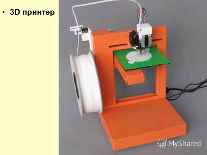 29;
29;
Enter value in command M851 Z-1.29;
We save the entered values in EEPROM with the M500 command;
Checking if the offset is set correctly. We send the G28 command, after homing we put the leaf on the center of the table, we send the G1 Z0 command and check the height of the nozzle with the leaf. About the Z axis I advise you to install 2 motors, otherwise sooner or later there will be a distortion, and you will have to constantly adjust the desktop, putting coins on one side.
Cracks between Z layers Since I use a propeller coupled to the motors, cracks appear when I print vertically at 0.2 scale. Here are the corrective actions:
- Buy an engine with a screw, abandoning the couplings. Haven't tried it, but advice has been given
- Adjusts the plastic feed in the Marlin. That is, when applying by 1 cm, the plastic should come out by 1 cm. This is obvious, but I didn’t bother with it at first, because it works like that, and you can also adjust the feed programmatically.
- Tighten the straps. This will flatten the walls slightly.
- Increase temperature. I use 240 against manufacturer advice. At the same time, plastic is perfectly fused, so that the lines are not visible. The only thing is that the power supply can not pull out 245 degrees, and sometimes the temperature "leaves" at 240. Well, since my extruder is "weak", it helps him push the plastic.
- Increase feed. At 10%, see if not satisfied, continue to increase. up to 150%
- If the problem persists at 150%, the nozzle is clogged.
About changing and cleaning nozzles Since I'm too lazy to unscrew the nozzle, I just bought two hot ends, and set the nozzles to 0.2 and 0.4. Given that the nozzles are made of brass, they gradually turn from hexagonal to round.
The nozzle must be removed at a temperature higher than the printing temperature, if you do not want the plastic to flood the model. Well it is clear. The nozzles themselves are not expensive, and this is a consumable, but they can be heated on a gas stove to red - all the garbage will burn out and they can be reused.
The perpendicularity of the model To check, just print a cube and measure the hypotenuses of the corresponding angles. They must be equal. If the problem is in XY:
- I typed a square - just a couple of lines. Checked their parallelism to the axes. They are not parallel, but it's not scary ... I loosened the straps and tightened them so as to compensate for the distortion. That is, one of them needs to be pulled a little harder, and then carefully tighten the whole thing.
If there is a problem in the Z axis: - With a high degree of probability, the pulley on the engine spun. This infection can work normally with you, but during the printing process, skip part of the belt forward, gradually distorting the part.
Well, in general, everything should be tightly screwed ideally. Although I still scored on some "extra screws" in the design.
Printing paused in the middle of printing Causes:
- USB connection to PC. I don't know how it is with 1000 units, but mine at 500 regularly disconnected equipment that could not power. So I connect the printer through the docking station.
- The box for Arduino presses on the reset button. I have an opening box, and the lid is just opposite the reset button. The hole for her is displaced and I generally scored on it.
In general about printing other people's models: This applies to mechanics and old projects. If you can use, say, Blender, print test patterns for teeth, holes, grooves. the prospect of grinding holes in a project that has been printed for at least 5 hours is of little interest.
For the price of : If you have tools, nothing will burn out, everything will work out the first time, do not experiment, but do not buy profiles - you can meet 20-25 thousand for 2021. Get an accurate, scalable printer that prints meter by meter.
Link:
If anyone wants to try their luck, link, respectively, to the project, connecting the board, setting up the firmware:
https://www.thingiverse.com/thing:2254103
https://3d-diy. ru/blog/3d-printery/podklyuchenie-elektroniki-ramps-1-4-k-3d-printeru/
https://3d-diy.ru/blog/3d-printery/nastrojka-proshivki-marlin/
Questions will arise in process - ask.
Expand
05/14/2022 22:55link29.6
MistSon
Expand
05/14/202219:07link29.8
Memron
You voted for Purple Rain and SHE'S DONE! Now reinforced in 16 different locations with screws and steel rods, she's heavier than proto #1 at 9.72 pounds / 4.40 kg, measuring 38.5" / 98 cm. Ready for the PAX East durability test!
You voted for Purple Rain and SHE'S READY !Now reinforced in 16 different places with screws and steel rods, it is heavier than the prototype at 4.40 kilos, 98 cm in length.Ready for strength testing for PAX East(Boston gaming expo)
Expand
17.04.202213:49link8.6
fghjk
When dad got a 3D printer and needed to take a sample of the chair for analysis.

Expand
04/16/202212:35link98.3
Computer animation. GIF animation in GIMP
Similar presentations:
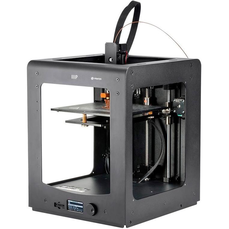
3D printing and 3D printer
Quality management systems requirements. Development of the ISO 9001
standardOperating system. Purpose and main functions
Adobe Photoshop
AutoCAD history and features
Microsoft Excel
Cloud technologies
Microsoft Corporation and Features
Web design
Topic 2. Application packages
Computer animation.
GIMP GIF animation
Lesson
2. Homework
Study §26, §27Study presentation.
3. Making motion pictures
Nowadays, there are specialprograms that greatly facilitate the work of animators.
4. Making motion pictures
BeforeTo create a 10-minute
cartoon
, artist
needed about
years of work.
Nowadays
!
To create a cartoon
with a duration of 1 minute
, it is necessary to create about 1500
images.
The artist is able
to complete a 10 minute film
in 1-2 weeks.
Meaning of words
• The word "cartoon" translated from 9Latin 0017 means multiplication,
increase, increase, reproduction.
• The word "animation" (eng. Animation) -
animation, animation.
The concept of animation
Animation is the creation of the illusion of movement of
objects on the monitor screen.
Computer animation uses fast-paced frames, which
the human eye perceives as continuous movement.
7. Computer animation
Most common methodsGif-animation;
Flash animation;
Animation in presentation.
GIF animation
The GIF format supports animation
images. They are
a sequence of several
static frames, as well as information about how long
each frame should be shown on the screen
. Animation can be made cyclical
(eng. loop), then after the last frame
, the first frame will start playing, etc.
 0017 images capable of storing lossless compressed data with a
 palette of no more than 256 colors.
GIF animation software
There are a variety of programs that allow you to
create animation from ready-made images (various
gif animators, for example:
• Microsoft GIF Animator
• Ulead GIF Animator
• Babarosa GIF Animator
• AGif
• GIMP
GIMP
Graphic editor GIMP allows you to create
GIF animations, as well as open and edit
GIF animation created by other means.
Layers
• To create an animated gif, you need to have several layers
Consider the simplest example. Create a new
image. Leave the bottom layer white. On
the other four draw the letters of the word
GIMP appearing. The easiest way to do this is to write
lettering on a new layer, then create four copies of this
layer and erase unnecessary letters in each of them.
• This will result in five layers, one of which is
the background, the other four are letter by letter
the GIMP gathering word:
Saving the GIF
• Save the resulting image as a gif (File
Export As).
 GIMP will then prompt
 for you to export the image as a gif. In doing so, it will give
the choice of whether to merge the layers into a single image or
save them as an animation.
Animation parameters
• Infinite loop. If this parameter is enabled, the interleaving of
layers will be performed indefinitely, i.e. after display
of the last layer will be displayed first. If this option is
disabled, then the animation will be played once and stop at the
image of the last layer.
• Delay between frames - time in microseconds, which by default
will display each layer.
• Frame positioning - has three modes.
First (default) - Never mind, GIMP will handle
on its own.
Second - Overlay layers, superimposes one layer on another without
removing the previous ones, i.e. unites them. So if you have
there are transparent places in the layers, the previous layers will show through them
. By default, GIMP usually uses this
mode as the most flexible.

Third mode - One frame per layer, replaces the previous layer with a
new one.
Example
• Use the default layer layout, and set the time
between frames to 200. The result should be
this gif: each layer in brackets
added parameter - display time. Thus, by changing the value in brackets
, each layer
can be given its own personal display time. For example, set
to 500 for the last layer so that
the full label stays on the screen longer.
Filters
It's time to turn to the special item
of the menu Filters - Animation. It contains three items -
Playback, Optimization and Deoptimization.
Let's figure out what's what:
• Playback. This item allows us
play fresh animation
image:
Optimization
Optimization. Each layer in an animated gif is, in fact, a separate image
and when saving a gif as an animation, we save several images
at once. Thus, with a large number of layers
, the size of our animated gif will grow right before our eyes
, which is not good, given the desire to minimize
the size of images for the web.
 One way out, maybe
 to be a manual reduction in the size of each layer and the destruction of
extra pieces.
The filter does the following: it calculates each layer and finds
changed points relative to the previous one and leaves only them,
changing the layer size to the minimum possible (ie cutting off
extreme changed points). In this case, all unchanged points
inside this layer will be replaced with transparent ones. Take a newly created
gif with GIMP caption and apply this filter.
Optimization
As you can see, there is only one letter left in each layer, and the whole
white color has been replaced with a transparent one. it makes no sense to drag it into
each layer, having a single white background for all. In addition, another parameter appeared in the name of the
layer in brackets - combine. This is exactly
and there is a frame layout mode. After applying the filter
Optimization, this mode will always have the value combine, i.
 e.
e. the new frame will be added to the previous ones. Try to change
this parameter to replace value and you will get approximately
the following:
De-optimization
De-optimization – inverse optimization filter. It
can come in handy when you need to make changes
to an optimized image.
Attention!
Optimization of layers allows you to significantly reduce the size of the
animation image.
Task 1
Simple animation
Each animation frame is a separate layer.
1. Choose File ► Open as
Layers from the top menu and select the pause.png,
letter-m.png, letter-i.png, and letter-r.png files.
Task 1
2. Rearrange the layers so that the layer with the letter M
is at the very bottom, then the layer with the letter I,
then the layer with the letter P, and at the very top is the layer
"pause". Save the resulting file with 4
layers as message.xcf (File
Save As).
3. Open the filter window Animation
Playback and start the animation by clicking the
Play button.