How to 3d scanner
How to Use 3D Scanning and 3D Printing for Reverse Engineering
Reverse engineering is a powerful way to create digital designs from a physical part, and can be a valuable tool in your prototyping toolkit alongside technologies like 3D scanning and 3D printing.
3D scanners measure complex objects very quickly, and can speed up your design workflow tremendously when real-life references are involved. With the ability to capture and modify physical shapes, you can design 3D printed parts that fit perfectly on existing products of all kinds. 3D printed jigs allow you to repeatedly locate a drill or saw, or assemble parts precisely with adhesive. Create close-fitting, reusable masks for sandblasting, painting, or etching.
In this post, we’ll walk through the step-by-step reverse engineering process for an aftermarket digital gauge and explain how to scan a part for 3D printing, with tips along the way for using the right reverse engineering tools, from CAD software to to 3D scanners and 3D printers.
For a full breakdown of 3D scanning workflows and technologies, download our white paper.
Download the White Paper
Looking for a 3D scanner for your 3D printer? Read our detailed guide on choosing the best 3D scanner to use with your 3D printer.
One of the biggest challenges people encounter when converting physical objects to digital is a major incompatibility between two different types of 3D models: meshes and solids.
A 3D scanner outputs a mesh, rather than a constructive “solid” model. Meshes need to be reverse engineered to be made editable.
Meshes are the main output of all 3D scanners, and the format commonly understood by 3D printers (STLs). A mesh represents the surface of a shape with a large number of triangles, connected edge to edge. Mesh models don’t contain any information about the object, besides the position of the triangles that define the shape.
On the other hand, engineers are trained to work with solid models. Solid models hold information about how an object is designed, and this information is explicitly encoded into the model as features in a ‘stack’ of logical steps. In solid CAD, it’s possible to change the dimensions for a single feature, and the rest of the model will update to accommodate the change.
Since meshes lack information about the construction of the object, the ways you can alter a mesh model are limited—CAD software like Solidworks and Onshape can’t directly modify meshes. If you need to make major modifications to the underlying design of a scanned part, the mesh needs to be converted to a solid CAD drawing: this process is reverse engineering.
Reverse engineering is important when you want to create new parts that reference or incorporate older designs, where the original CAD design isn’t accessible.
For example, you can create replacement parts that match the original design of damaged existing pieces, or use reverse engineering processes to integrate complex surfaces from existing objects into 3D printable jigs, which are useful when modifying mass manufactured and handcrafted products.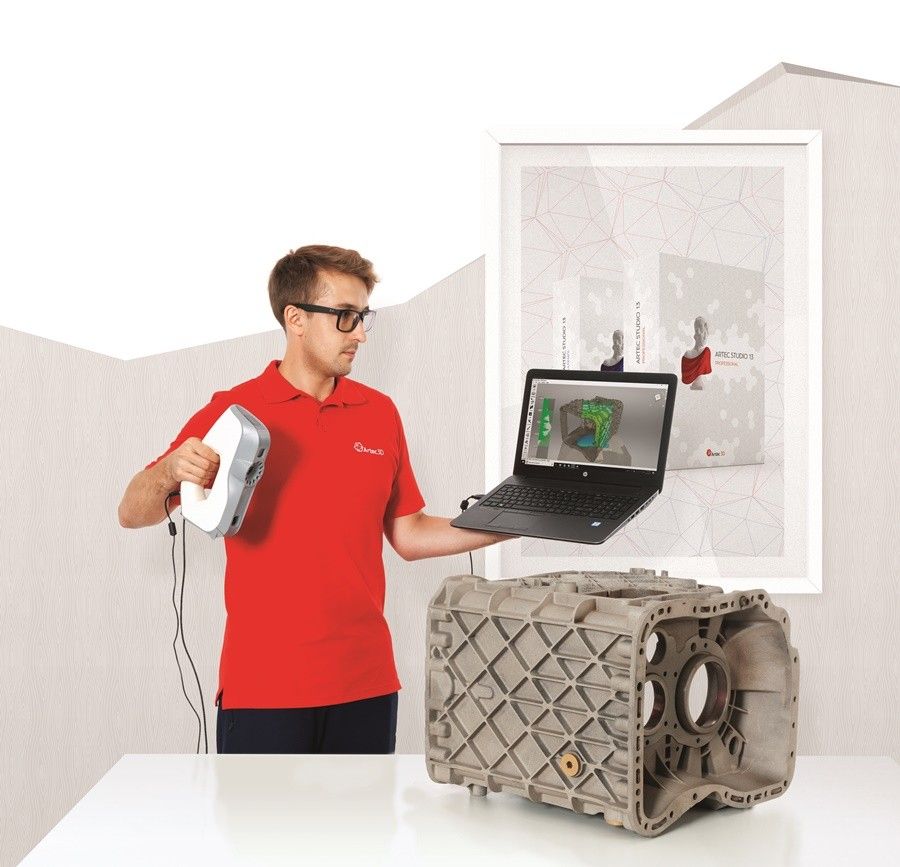
To demonstrate the basic steps in a reverse engineering workflow, let's take a look at the process for creating an assembly jig for an aftermarket digital gauge that fits onto the air vent of a Volkswagen Golf.
Spray coat the object with a temporary matte powder to improve scan accuracy. Even slightly glossy surfaces tend to degrade scan quality, while reflective and transparent surfaces cannot be scanned at all without a matte coating.
Use a temporary matte powder to improve the scan accuracy of your object.
Use a high accuracy 3D scanner to capture the important sections of the part. Tabletop structure light or laser scanners are the right tools for the job, with accuracy of ±100 or better.
Learn more about how to choose the right 3D scanner for your application in our 3D scanning white paper:
Note: You may need to orient and re-scan your object several times if the object has deep recesses.
Some scanners produce extremely large mesh files, which will make later steps grind to a halt.
Scanner software repairs small gaps and simplifies the scan, making the data more manageable in CAD. Try to reduce the model as much as possible without destroying important details.
Tip: If you need more control, Meshmixer is a great choice for refining scanned meshes.
Import the mesh into CAD software equipped with reverse engineering tools. Geomagic for Solidworks is a powerful choice for resurfacing complex, organic shapes.
If you are reverse engineering a part with simpler flat surfaces, Xtract3D is a less expensive, lightweight alternative.
In this step, move and rotate the scan mesh into alignment with any existing design components.
Tip: Make drawing easier by rotating and aligning your scan to face the orthographic view directions.
There are three paths to extract the shape of the scan in order to create a solid model that is editable with CAD tools: semi-automatic surfacing, automatic surfacing, and manual redrawing.
Semi-automatic surfacing
Complex curved surfaces are difficult to manually draw, so you may choose to use semi-automatic surfacing. This function generates surfaces that fit to detected regions of the scan. By varying the sensitivity of the surface detection function, different surfaces will be found.
Tip: Geomagic for Solidworks detects surfaces on the scan to fit 3D curves. Use a “brush” to manually add or subtract areas on the scan from each region.
You may need to repeat this process several times with different sensitivity settings to detect all your surfaces. These surfaces can then be trimmed and knit together to create an editable solid.
Use semi-automatic surfacing to re-create curved shapes when you want maximum editability later on, and when sharp edge accuracy is important.
The re-surfaced result, after trimming.
Automatic surfacing generates a solid model from any watertight scan. You can use standard CAD tools to subtract and add to this auto-surfaced body, but it will be more difficult to move basic features around on the body itself.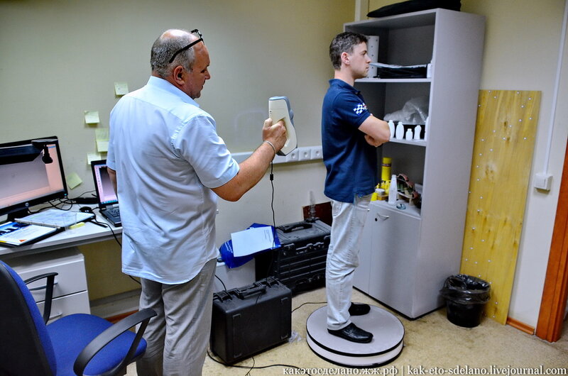
You may not need control over edge placement. For example, if you are scanning a part of the human body to create custom ergonomically-shaped products, or want to create a jig to precisely or repeatably modify a handmade object. In these cases, automatic surfacing is a great way to save modeling time.
Note: Compare the results of a automatic surfacing to semi-automatic surfacing: some accuracy is lost, especially around sharp edges.
For simple features such as bosses, holes, and pockets, it’s usually fastest and most accurate to redraw the features using the scan model as a reference. Reverse engineering software allows you to create sketch planes aligned with flat surfaces on the scan and to extract cross sections from the scan mesh, which helps you match the shape of the original object.
Once the scan has been converted to a solid, it can be subtracted from another solid body to create a jig that securely holds the original part.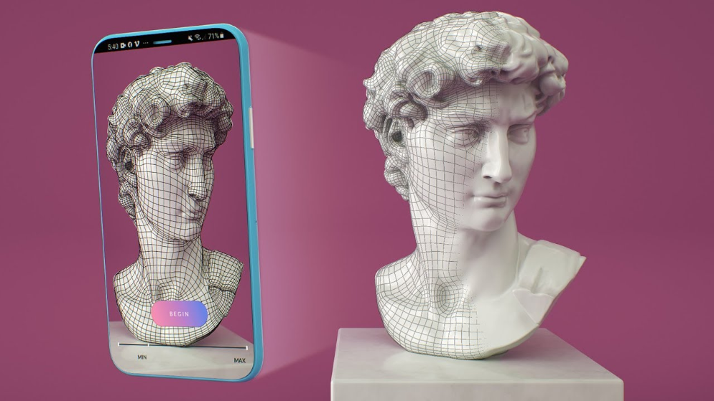
The design of the new gauge component also references the dimensions of the scan, using curves extracted with semi-automatic surfacing.
Printing the jig on a Formlabs stereolithography (SLA) 3D printer gives you a high degree of accuracy comparable to the output of engineering-grade 3D scanners. Use Formlabs Rigid 4000 Resin for its strength and precision.
Once these steps are complete, the 3D printed jig is ready to use to assemble the new gauge onto the OEM air vent.
The final 3D printed assembly jig, printed in Rigid 4000 Resin.
How to Scan 3D Objects for 3D Printing – 3D Printerly
3D scanning objects for 3D printing can be tricky to get the hang of, but once you learn the right software and tips to follow, you can create some pretty cool models. This article will give you some good insights into scanning objects to create 3D prints.
To 3D scan 3D objects for 3D printing, you either want to get a 3D scanner or use your phone/camera to take several pictures around the object and stitch them together using photogrammetry to create a 3D scan.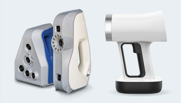 Make sure you have good lighting while scanning to get the best results.
Keep on reading for more information and tips to 3D scan objects for 3D printing.
Can I Scan an Object to 3D Print?
Yes, you can scan an object to 3D print using various scanning methods. One example of this is by a grad student who 3D scanned and 3D printed a Shuvosaurid Skeleton for a museum exhibit. It’s an ancient crocodile-like creature that he 3D scanned using a premium professional scanner called the Artec Spider.
It’s currently priced at around $25,000 but you can get much cheaper 3D scanners, or use free options such as photogrammetry which is creating 3D scans through taking several pictures.
He mentioned an open access repository called MorphoSource which is a collection of several 3D scans of animals and skeletons.
This student further revealed that he then used a visualization software called AVIZO to prepare STLs for the surface of each scan, after which he 3D printed it.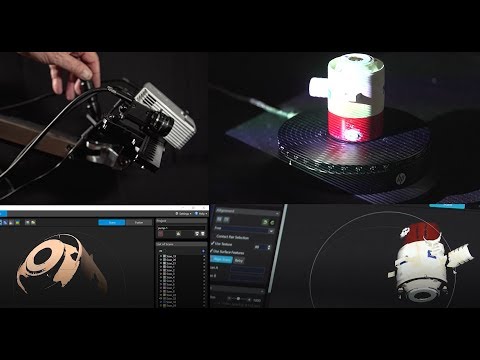
When it comes to more standard objects that you might have around the house, or even with cars parts, it’s definitely possible to 3D scan and 3D print them. People have been doing it for many years successfully.
I also came across a user who scanned and printed his friend’s farm with the help of a drone. Not only was it a significant success, but it had a fantastic architectural look.
I scanned and 3d printed a friends farm using a drone and my new 3d printer. from 3Dprinting
He started by generating a mesh model after mapping using Pix4D and then processed it afterward using Meshmixer. The Pix4D was costly, but there are free alternatives such as Meshroom that you can use if you can’t bear the cost.
It took around 200 photos and in terms of the scaled dimensions and detail from the drone, it works out to be around 3cm per pixel. The resolution mainly depends on the drone’s camera and height of flight.
3D scanning is not only limited to what you interact with daily, but as seen on NASA’s 3D scan page, many types of objects can also be 3D scanned.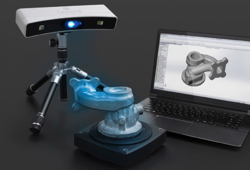
You can see more about this on the NASA page of printable 3D scans and see several 3D scans of space-related objects like craters, satellites, rockets, and more.
How to Scan 3D Objects for 3D Printing
There are a few methods on how to scan 3D models for 3D printing:
- Using an Android or iPhone App
- Photogrammetry
- Paper Scanner
Using an Android or iPhone App
From what I have gathered, it’s possible to scan 3D objects straight from the apps you have installed on your device. This is possible because most newly manufactured phones have LiDAR (light detection and ranging) by default.
In addition, some apps are free, and others require paying for them first before using them. See below a brief explanation of some of the apps.
1. Polycam App
The Polycam app is a popular 3D scanning app that works with Apple products like the iPhone or the iPad. It currently has an app rating of 4.8/5.0 with over 8,000 ratings at time of writing.
It’s described as the leading 3D capture application for the iPhone and iPad. You can create plenty of high quality 3D models from photos, as well as quickly generate scans of spaces using the LiDAR sensor.
It also gives you the ability to edit your 3D scans directly from your device, as well as export them in many file formats. You can then share your 3D scans with other people, as well as the Polycam community using Polycam Web.
Check out the video below to see how a Polycam user scans a large rock and captures plenty of detail.
The lighting is a very important factor when it comes to 3D scanning, so consider that when you are scanning your objects. The best type of light is indirect light like shade, but not direct sunlight.
You can check out Polycam’s Official website or the Polycam App page.
2. Trnio App
The Trnio app is a great method of 3D scanning objects for 3D printing. Many people have created some stunning 3D prints using existing objects, then scaling them as they desire to create new pieces.
One great example of this is the video below by Andrew Sink who 3D scanned some Halloween decorations and made it into a pendant for a necklace. He also used Meshmixer to help achieve this result.
Previous versions of the app weren’t the best, but they have done some useful updates to scan objects faster and easier. You no longer have to tap during scanning, and the app automatically records and compiles the video frames.
This is a premium app so you’ll have to pay to download it, currently priced at $4.99 at time of writing.
You can check out the Trnio App page or the Trnio Official website.
Photogrammetry
Photogrammetry is an effective method of 3D scanning objects, used as a basis for many apps. You can use raw photos directly from your phone and import than into a specialized software to create a 3D digital image.
It’s a free method and has some impressive accuracy. Check out the video below by Josef Prusa showing off 3D scanning from just a phone with the photogrammetry technique.
1. Use Camera – Phone/GoPro Camera
Someone had posted how he scanned a broken stone and then printed it, and it came out perfectly.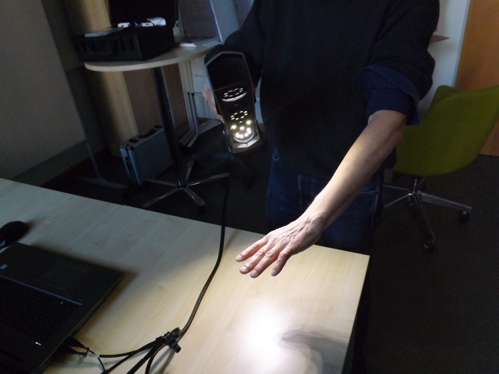 GoPro camera assisted him in achieving this. He also used COLMAP, Prusa MK3S, and Meshlab, and he reiterated how important lighting is.
Uniform lighting is the key to success with COLMAP, and outdoor during an overcast day gives the best results. Check out the video below for a useful COLMAP tutorial.
He also mentioned that it is difficult to deal with shiny objects.
He actually used a video clip as the scan source and exported 95 frames, then used them in COLMAP to create a 3D model.
He also mentions that he did some tests with Meshroom in terms of getting good scans with bad lighting and it does a better job at handling unevenly lit objects.
You have to handle the GoPro camera carefully because you may get a distorted image if you do not take care of the wide-angle.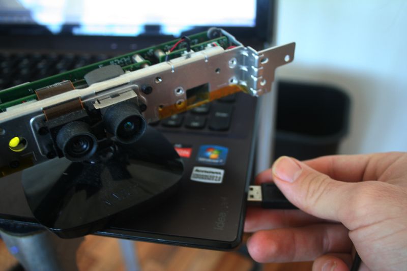 Follow the link to get a detailed explanation.
2. Professional Handheld Scanner – Thunk3D Fisher
There are many professional handheld scanners out there with varying levels of resolution, but for this example, we’ll look at the Thunk3D Fisher.
Even though the scanner takes detailed pictures and is specialized, it still falls under photogrammetry. One 3D user wrote about how through 3D scanning and printing, he managed to come up with Mazda B1600 front headlights.
3d scanning and 3d printing a perfect match, we recreated a front headlight for a Mazda B1600. Car owner only had right side, scanned and flipped it fits the left side. Printed in generic resin and post processed with epoxy and painted black. from 3Dprinting
The car owner only scanned the right side using a handheld Thunk3D Fisher scanner then flipped it to fit on the left side.
This scanner gives accurate scans and it is said to be ideal for scanning large objects.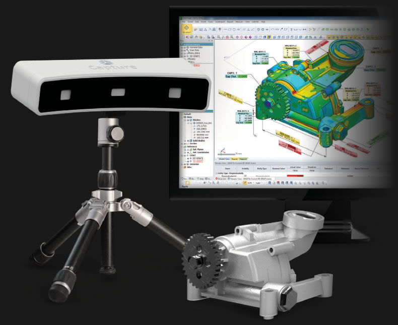 It is also perfect for objects that have intricate details. It uses a structured light technology.
The good thing with this scanner is that it scans objects ranging from 5-500 cm in high resolution and 2-4 cm in low resolution. It has free software that is frequently updated. The exciting bit is that the Thunk3D Fisher Scanner has additional software for Archer and Fisher 3D scanners.
3. Raspberry Pi-Based OpenScan Mini
I came across a piece on how someone had used a Raspberry Pi-based scanner to scan a 3D printed rook. It was 3D scanned using a combination of the Raspberry Pi based OpenScan Mini, along with an Arducam 16mp camera with autofocus. They mentioned that the increase in detail was significant.
The camera resolution for these types of scans is very important, but proper lighting along with surface preparation may even be more important. Even if you had a bad quality camera, if you have good lighting and a surface with rich features, you can still get pretty good results.
3D scanning this 3D printed rook showing some incredible details – printed at 50mm height and scanned with the Raspberry Pi based OpenScan Mini (link&details in comment) from 3Dprinting
He went ahead to reveal that if you want to use this scanner, you should be well aware of how it depends on the Pi camera. You can expect excellent results when using the two together.
Using a Paper Scanner
It’s not the usual method but you can actually 3D scan using a paper scanner. A great example of this in action is with CHEP who experienced a broken clip, then went on to glue the pieces together to then 3D scan it on a paper scanner.
You then take the PNG file and convert it to an SVG file.
Once you’re through with the conversion, you can download it to your chosen CAD program. Then, after a few processes, you can convert it into an STL file before taking it to Cura for slicing as you prepare to 3D print it.
Check out the video for a visual tutorial on getting this done.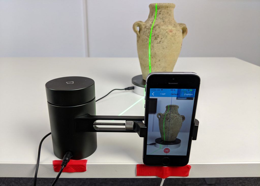
How Much Does it Cost to 3D Scan an Object?
A 3D scanning service can cost anywhere from $50-$800+ depending on various factors such as size of the object, level of detail the object has, where the object is located and so on. You can 3D scan your own objects for free using photogrammetry and free software. A basic 3D scanner costs around $300.
There are even options to rent your own professional scanner so you can get a really high quality scan for several objects.
Many phone 3D scanning apps are free as well. When it comes to professional 3D scanners, these can cost around $50 for a DIY kit, upwards of $500+ for low range scanners.
3D scanners can definitely get pricey when you are looking for high specs, like the Artec Eva for around $15,000.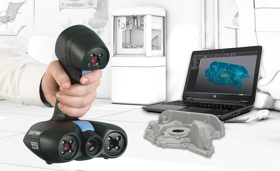
You should also be able to find 3D scanning services in your local area through searching on places like Google, and these costs will vary. Something like ExactMetrology in the US and Superscan3D in the UK are some popular 3D scanning services.
Superscan3D determine the different factors for the cost of 3D scanning being:
- Size of the object to be 3D scanned
- Level of detail the object has or complex curves/crevices
- Type of material to be scanned
- Where the object is located
- Levels of post-processing required to get the model ready for its application
Check out this article from Artec 3D for a more detailed explanation of 3D scanner costs.
Can You 3D Scan an Object for Free?
Yes, you can successfully 3D scan an object for free using various software 3D scanning apps, as well as photogrammetry which is using a series of photos of your desired model and a specialized software to create a 3D model. These methods can definitely create high quality 3D scans that can be 3D printed for free.
Check out the video below for a visual explanation of how to 3D scan with Meshroom for free.
Turning a 3D scan or photos to an STL file can be done using software like this. They usually have an export option to turn the series or photos or scans into an STL file that can be 3D printed. It’s a great method to make 3D scans printable.
Almost DIY 3d scanner for home / Sudo Null IT News scanning is out of the question.
But the main plus that I took out from the article is the David-3D scanning program, which really has a good manual in Russian and, importantly, buying a license is the last thing required, since the free version is limited only to saving the scan result. Everything else works in full, which means that it is quite possible to test the program, settings and your hardware as much as you like. And if you don’t need the result with high accuracy, then you can do without buying a license at all.
I needed accuracy, since the main thing I wanted to scan was miniatures from the Warhammer board game (so that later I could change them as I wanted and print them :)). The height of these "soldiers" is only 3 cm, but this does not prevent them from being very detailed.
If you do not need to shoot such small objects, then your equipment requirements will be lower, which means that it will be much easier to assemble a similar scanner for yourself.
The principle of the program, and accordingly scanning, is well described in the article, which was linked above (I think it is not necessary to duplicate this). It is advisable to read that article first, as this one will be in some way its logical continuation.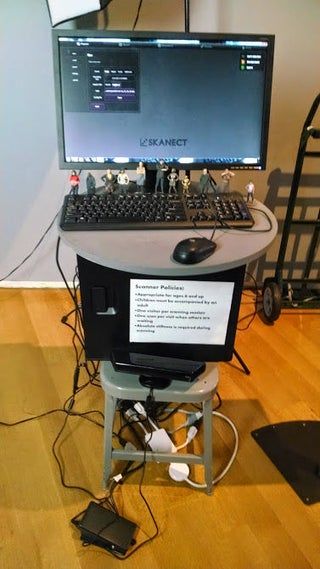
But let's start in order. What you need to try 3D scanning at home:
1 - projector.
2 - webcam.
That's all, the short list turned out surprisingly well. However, if you want to get very accurate and high-quality scans, then you will have to modify some things with pens. Of course, you can’t do without additional costs, but in the end it will still cost less than buying any of the commercially available 3D scanners, and the quality of the result can be obtained much better.
Now, in order and in detail.
PROJECTOR.
I, like the author of the previous article, started my first experiments on scanning with a laser pointer, but they immediately showed how inconvenient this method is. There are several disadvantages here at once:
- the impossibility of obtaining a beam with a sufficiently thin line. Moreover, when you turn the pointer, the distance from the lens to the object changes, which means the focus is lost.
- if you need to scan regularly, turn the laser pointer with sufficient accuracy and smoothness by hand is very difficult, and tiringly easy - the hands are not such a stable tool when it comes to a long time.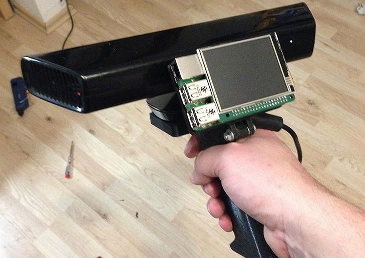
- you have to scan in the dark so that only the laser line is visible and nothing more.
And if the second drawback can still be dealt with by creating a special rotary mechanism (although this is already not such an easy task, in any case, this cannot be done in 5 minutes on the knee), then getting rid of the first drawback is more expensive.
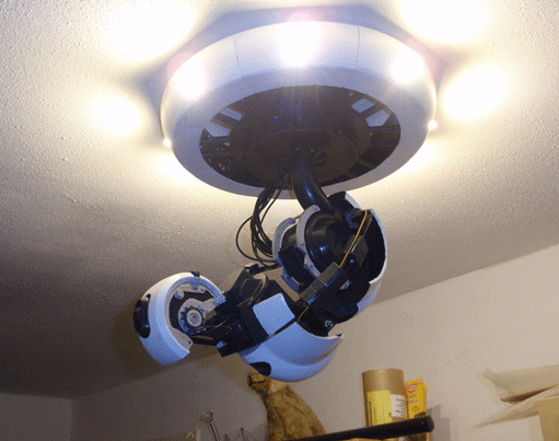
When I realized all this, I decided to try scanning with a projector, for which I borrowed some simple model from a friend.
A small clarification should be made here - in the last article, the author mentioned the possibility of scanning using a projector, although the proposal was, in my opinion, very strange -
A projector with a powerful lamp is suitable, the light of which must be directed through a narrow slit to the object being scanned
This may have been the only option in earlier versions of the program, but in version 3 that I experimented with, the projector was used much better, because there's a feature called Structured Light Scanning (SLS).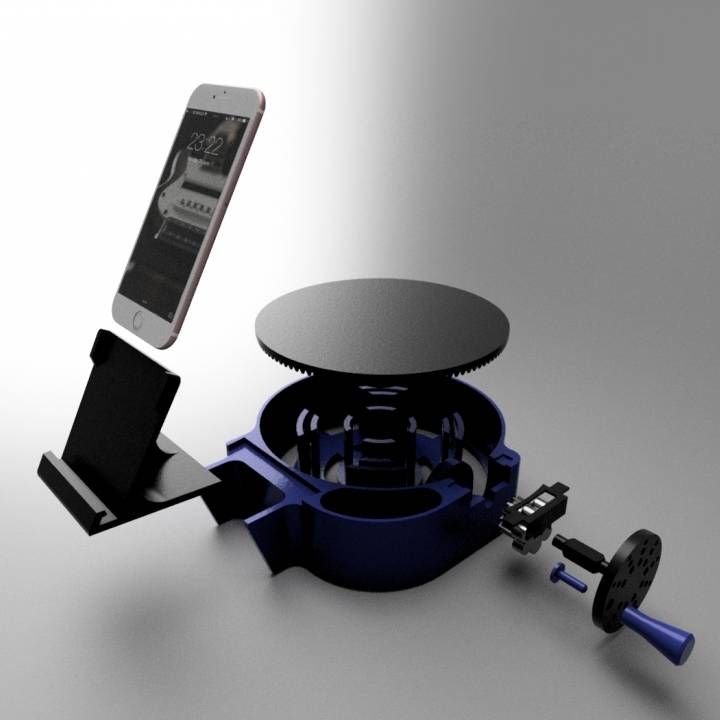 Unlike laser scanning, the projector immediately projects a grid of vertical and horizontal lines of various thicknesses onto the object, which reduces the scanning time by an order of magnitude and allows you to automatically shoot the color texture of the object. Well, with good focus, a 1 pixel wide line is much thinner than you can get from an inexpensive laser pointer.
Unfortunately, I didn’t take pictures from those first experiments, and there wasn’t much to take pictures of - the projector is on the table, next to it is a webcam, all of this looks in one direction :) However, even such a simple design showed that this option much better both in terms of scanning speed and quality. Then I decided to buy myself a projector for these purposes.
The criteria for choosing a projector were simple - higher resolution, lower price and dimensions :)
The choice settled on IconBit Tbright x100 - an ultra-compact DLP LED projector, 1080 resolution - at that time it seemed to me that you couldn’t imagine better, but as it turned out later, I was wrong, although while working with it, I got a lot of interesting experience.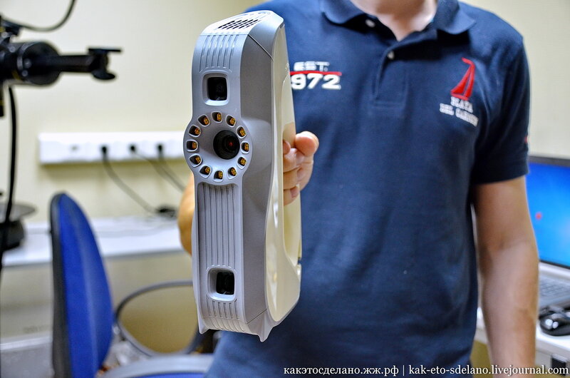
The first problem that occurs when scanning a small object with a projector is that for best results, the size of the projected grid should roughly match the size of the object being scanned. This projector made it possible to obtain the smallest screen diagonal at the closest focus - about 22 cm. Agree that against such a background, a miniature 3 cm high is far from the concept of "approximately equal sizes." The answer was found on the official forum - people in such cases install camera lenses on the projector for macro photography. Given the small size of the projector lens, I opted for marumi lenses with a thread diameter of 34mm.
Using two of these kits, I managed to get a projector screen with a diagonal of only about 3 cm. Which turned out to be quite enough to make my first microscan -
This is a single scan, therefore there are “holes” on the model, torn edges and etc. By turning the coin and scanning from different angles, you can get several of these scans, which are subsequently combined into one object (the scanning program itself allows you to correctly combine different scans, stitch them together and save them as a single object).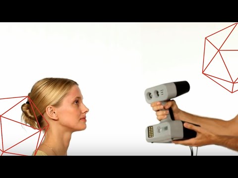 In the process of stitching, the shape of the object is also specified. But saving the results of such stitching is possible only after purchasing a license.
And now the moment has come for the first thing that is not necessary for scanning, but with it the process is much more convenient - this is a stand for a projector with a camera. The calibration process itself is needed not only for the program to recognize the parameters of the equipment - the software must also calculate the relative position of the camera and the projector. In the course of work, their change is not allowed (as well as changing the focus of the camera), which means that it is necessary to firmly fix all this, because the number of scans can be large even for one object.
David's main page shows a similar system - it is nothing complicated. Yes, and looking through the forum and seeing how different people organize it for themselves, I realized that nothing complicated is required here.
For these purposes, a stand was taken from a burned-out LCD monitor, and plexiglass from it, cut and glued like this design, as it looked in the first version , which allowed changing the screen diagonal and scanning objects of different sizes.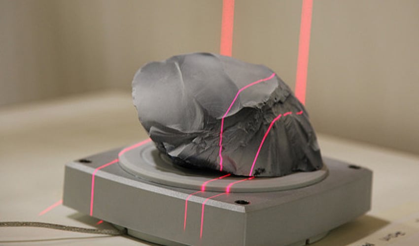
It should also be mentioned that scanning with a projector does not require the constant presence of calibration panels in the field of view. After the calibration is done, they can be removed. This allows, having calibrated the installation, to easily transfer it, move it, etc.
That is, you can use a large calibration template to calibrate at home on the walls, and then go outside with this stand and laptop and scan your car, for example. We took a smaller template, put a couple of lenses - and you can scan jewelry.
Recently, the company has released an improved scanning kit, here the stand looks much more serious and interesting -
2000 euros is not entirely justified, it is not difficult to assemble something like this yourself and much cheaper.
Let's go back to the projector. As it turned out, this projector had one major disadvantage for being used in a scanner, namely its native resolution (854*480). And everything would be fine if it produced the same output, but alas, the picture was converted to standard resolutions (such as 1024 * 768), and as a result, a line one pixel wide was somewhere brighter in different parts of the screen, where - something dimmer, somewhere already and somewhere wider . .. All this had a negative effect on the quality of scanning, expressed in the form of ripples and stripes on the resulting model.
By that time, I was already thinking about buying a projector for a stereolithographic 3D printer (http://geektimes.ru/post/245590/). After considering several options, I settled on the Acer P1500 model, because. it does not need any modifications to be used in a printer (this projector, without any lenses, is able to give a focused image on a screen of about 4 * 7 cm). So, for the scanner, it will fit perfectly. At the same time, the resolution of 1920 * 1080 is real. And so it happened, I still use this projector and am completely satisfied with the results.
CAMERA.
The criteria for choosing a camera were the same as when choosing a projector. Having gone shopping, I stopped at the Logitech C615. The scan of the coin was made from it, without any modifications. But when I tried to scan the figurine, I ran into a problem called "depth of field".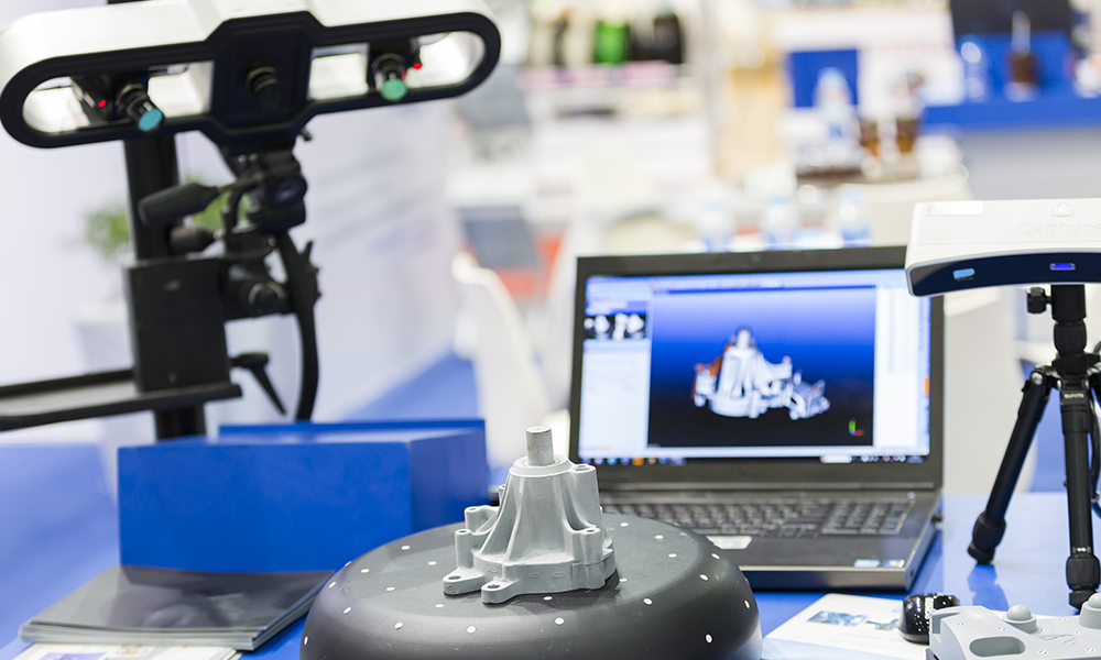 When the object is so small, then in fact we get macro photography, and sharpness with such shooting is achieved only in a small segment, literally just a couple of millimeters (which is why the coin was scanned well - the relief fit perfectly into the sharpness area). It was decided to convert the camera to a different lens. Several different lenses were ordered on Ebay for testing, and a new case was cut out for the camera board. The plan was like this0003
The final result was slightly different
The main idea, I think, is clear. And now, both on Thingiverse and on the forum of the program, you can download stl for printing cases for different types of webcams.
I had to remove the standard lens from the camera board, and as it turned out later, the IR filter was removed along with it, so be careful in this matter. The filter will then come in handy for use with other lenses, although you can buy them separately - the price is cheap.
Thus, I have formed such a collection of lenses.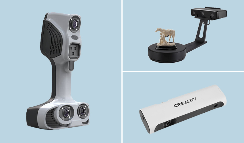
While I was waiting for the lenses to arrive, I was reading various photography forums. Studying the issue with depth of field, I found out that you can increase it by closing the lens aperture more. This means that the lens was required one in which it was possible to adjust the aperture (alas, among those ordered, not everyone had such an opportunity, but luckily I got a couple of them). In general, to improve the camera, it is desirable to have a varifocal lens with a zoom and an adjustable aperture. In practice, everything turned out the way it was in theory - closing the aperture, an increase in the depth of field was immediately visible, which made it possible to scan three-dimensional, but small objects.
The main lens I use is mounted on the camera in the photo above. The second, with an adjustable aperture, is the largest, in the center. I use it for very very small objects. The rest are without a diaphragm, so I don’t use them - it turned out that these two were quite enough.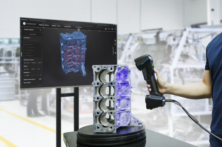
Now I plan to either find a webcam with a higher resolution (the quality and detail of the scans directly depends on the resolution of the camera), or try to use some digital camera for this purpose with the ability to shoot video - usually you can get a lot more resolution in them, and lenses are better.
Actually, this could be the end - it seems that he told about everything. I also thought that this was the end of my scanner assembly, but the farther into the forest ... While studying the forum of this program, I often came across various schemes of turntables - fortunately, the software allows you to automate the scanning process. After one scan, a command is sent to the com port, the turntable rotates, turning the object by a given number of degrees, and gives a command to the next scan. As a result, with one click of the mouse, we have circular scans of the object - it would seem, what more could you want? I tried this system with interest, but alas, I absolutely did not like this approach, and there are a couple of reasons for this.
1 – if the object has a complex shape, then simply rotating it will not be enough – you also need to tilt it in different directions so that the camera with the projector reaches all the depressions and other hard-to-reach places.
2 - even if there are no such places, and considering all the scans that were made, there are no parts left on the object that did not fall into the scan, the question of the accuracy of the scan remains.
Let's say that some part of the model on one of the scans came out perfectly. But this does not mean that on all the scans in which this part fell, it also looks perfect, and when stitching scans from different angles, the result will be averaged, which cannot please. The program allows you to slightly edit the received scans (you can cut out the unnecessary part). If we rotate the model by 20 degrees, then after a full rotation we will have 18 scans, the part we need may well be present on half of them, therefore, in order to leave the best result, we will need to remove this piece from 8 scans .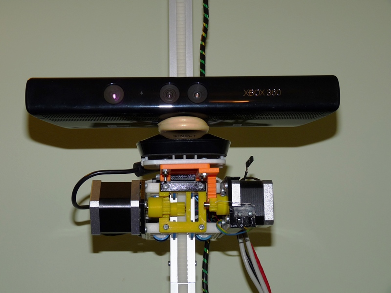 .. And such pieces with a complex There can be many models, as a result, almost half will be cut off from each scan, which is very laborious and time consuming.
Instead, it is better to immediately scan adjacent areas after the first scan and check the result. As soon as a piece is ready, we move on to scanning the next one, and so on, until the entire model is in perfect shape. This approach gives the best results in less time.
But the question of convenience arises. Agree, it’s inconvenient to manually try to rotate an object, looking not at it, but at the monitor - in order to control the hit on the lens without changing the distance to the camera and the projector at the same time (so as not to lose focus). With the next similar balancing act, I accidentally touched the camera, which accordingly knocked down the entire calibration, and the whole process had to be started anew. I categorically did not like this alignment, and after some thought I came up with a plan for such a design (which, as you understand, I subsequently assembled).
This is not a turntable in the usual sense of the term. Thanks to this design, I can not only rotate the model, but also tilt it as I need. In this case, the center of the model remains in the plane of focus, but even if not, you can move the mount with the model back and forth.
All this was assembled on arduino, a small control program was written, and as a result, now I don’t have to get up from the computer when scanning - using the program, I change the position of the object being scanned, and at the same time, right there, in the window cameras I choose the best angle for scanning.
Insides
I put the possibility of automatic scanning into the program, as well as scanning not only in a circle, but with inclinations of 45 degrees in one direction and the other, which gives three times more scans. Nevertheless, in the end, I still never use this opportunity - it's too inconvenient to sort through the resulting pile of scans and clean them from unsuccessful pieces.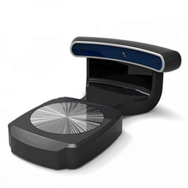
We should also mention some nuances of scanning.
1 - it is impossible to scan shiny and mirror surfaces. The light from them is reflected, or gives such a glare that the program cannot correctly recognize the line. If there is a need to scan such an object, then such parts will have to be masked with something (washable paint, paper tape, etc.).
2 - it is more convenient to scan monotonous objects, since when the camera is set to a light color, the projector's brightness is not so high, the exposure is low, etc. And a dark-colored object needs more brightness, so if you have a multi-colored object, then different parts of it require different settings to get the best result. Here, too, it is more convenient to use scanning the object in parts.
3 - if you want to immediately get a color texture, then please note that the settings of the camera and the projector for scanning do not affect the settings for removing the texture (the scan is generally done in black and white mode), so play around with the settings in the texture mode just as you would do in scan mode.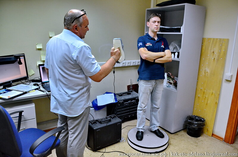
My scanning process now looks like this:
- Focusing the projector and camera
The projector's light is too bright and the projected grid is not visible in the photo, but here is the view from the camera in the program
- scanner calibration
printed on magnetic paper - so you can very quickly adjust to different sizes of scanned objects.
Software view
It is recommended that the combined angle between the beam of the projector and the camera be around 20 degrees. Therefore, such a stand is used - when scanning large objects (for example, a person), the camera should be set aside much further from the projector, but here they are close to me. The location of the camera relative to the projector can be only vertical, or only horizontal, depending on the geometry of the object. In this case, the arrangement is diagonal (13 degrees vertically and 36 degrees horizontally).
Scan results from different angles. These are already cleaned up scans, i.e. all unsuccessful and unnecessary parts (figure stand, mount that got into the frame) parts have been removed.
Combining scans for subsequent merging into one object
Due to the fact that each scan has its own color, it is convenient to control the correct alignment.
Well, after combining the scans from different angles, we get the following models
Miniature of Boromir from Lord of the Rings.
When scanning a multi-colored object, the result is slightly worse if you don't bother too much. But then you can get an object with a texture right away :) , even fingerprints people scan. And there are even scans of the same miniatures from Warhammer
In conclusion, I would like to say that no matter what hardware you use, no matter what expensive 3D scanner you buy, this is not a panacea for printing anything. Theoretically, of course, you can send the resulting object to the slicer and print, but there are several reasons why you should not do this, but in any case, you should study 3D graphics packages.
1 - The resulting scans, with good scan quality (and we want to get the best quality) have a lot of polygons. No, even is VERY a lot. The scan of Boromir after the merger contained more than 8 million polygons - not every slicer will be able to work with such an object.
2 - Any objects bear traces of assembly and manufacture. And if in reality needle files and sandpaper are used to fix this (and sometimes there are still inaccessible places where it is impossible to use tools), then working with a digital copy of an object, we can change it as we like - remove defects, improve detail, etc. .
3 - As I said at the beginning of the article, when I thought about the scanner, I did not want to print copies of objects, but change them as I please. I am not a sculptor, I do not have the tools, materials and skills to sculpt such a small model. But knowing how to work in 3D, it is much easier for me to scan a similar Boromir and make him some kind of Prince of Denmark.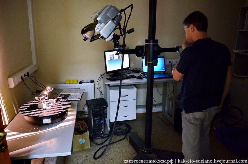
By the way, this model already contains almost 100 times fewer polygons than the scan result.
DIY 3D scanner
07/13/2016
Is a 3D scanner an expensive device that is inaccessible to a mere mortal? Not at all! Now you can create a 3D scanner yourself from improvised means or your own smartphone.
In order to construct a simple 3D scanner, you will need a high-quality webcam, a device that emits the thinnest possible laser beam, a calibration mounting angle that will allow you to fine-tune a home-made scanner, and, of course, a set of software for work with the received scan data.
The calibration angle is printed on the printer itself and then positioned to form a right angle. The item to be scanned will need to be placed in the calibration corner. A webcam is placed opposite the object so that the object is exactly in the center of the screen. The software allows you to calibrate the camera, using the same software to adjust the color of the laser. Then the laser beam should be smoothly drawn over the scanned object from all sides. The location of the laser then needs to be changed in order to complete several scans and thus cover the entire surface of the object. After the scan is completed, the program will be able to see a three-dimensional object. If you need to get a model with higher detail, you can use two webcams.
You can also create a 3D scanner yourself using a webcam and a projector. To do this, you will need two tripods, for the projector and for the webcam, a calibration panel, which you can also make yourself, a turntable and the DAVID-laserscanner software. The scanned object is placed vertically and rotated in a circle, thus 7-8 shots are taken. The scans are merged to form a single 3D image. After that, the object is rotated and scanned again in a circle. The scans of the two sides are connected and based on the received images, the program itself will create a 3D model that can be saved in the desired format for further processing.