Gcode optimizer 3d printer
This GCode Post-Processor Squeezes Lines Into Arcs
- by: Joshua Vasquez
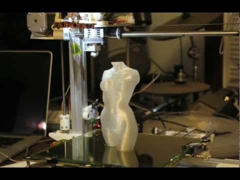
When the slicer software for a 3D printer model files into GCode, it’s essentially creating a sequential list of connected line segments, organized by layer. But when the features of the original model are dense, or when the model is representing small curves, slicers end up creating a proliferation of teeny segments to represent this information.
This is just the nature of the beast; lots of detail translates into lots of teeny segments. Unfortunately, some printers actually struggle to print these models at the desired speeds, not because of some mechanical limitation, but because the processor cannot recalculate the velocities of these segments fast enough. The result is that some printers simply stutter or slow down the print, resulting in print times that are much higher than they should be.
Enter Arc Welder, a GCode compression tool written by [FormerLurker] that scrutinizes GCode files, hunts for these tiny segments, and attempts to replace contiguous clusters of them with a smaller number of arcs. The result is that the number of GCode commands needed to represent the model drop dramatically as connected clusters of segment commands become single arc commands.
“Now wait”, you might say, “isn’t an arc an approximation of these line segments?” And yes–you’re right! But here lies the magic behind Arc Welder. The program is written such that arcs only replace segments if (1) an arc can completely intersect all the segment-to-segment intersections and (2) the error in distance between segment and arc representation is within a certain threshold. These constraints act such that the resulting post-processing is true to the original to a very high degree of detail.
A concise description of Arc Welder’s main algorithm as pulled from the docsThis whole program operates under the assumption that your 3D printer’s onboard motion controller accepts arc commands, specifically G2 and G3. A few years ago, this would’ve been uncommon since, technically, 3D printing and STL file only requires moving in straight line segments. But with more folks jumping on the bandwagon to use these motion control boards for other non-printing applications, we’re starting to see arc implementations on boards running Marlin, Smoothieware, and the Duet flavor of RepRap Firmware.
For the curious, this program is kindly both well documented on operating principles and open source. And if [FormerLurker] seems like a familiar name before–you’d be right–as they’re also the mind behind Octolapse, the 3D printing timelapse tool that’s a hobbyist crowd favorite. Finally, if you give Arc Welder a spin, why not show us what you get in the comments?
Thanks for the tip [ImpC]!
Learn How to Modify G-Code in Cura for 3D Printing – 3D Printerly
Modifying G-Code for your 3D prints can seem difficult and confusing at first, but it isn’t too hard to get the hang of.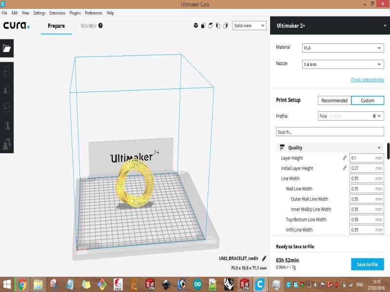 If you want to learn how to modify your G-Code in Cura, this article is for you.
Cura is a very popular slicer among 3D printing enthusiasts. It offers a way for users to customize their G-Code using placeholders. These placeholders are preset commands that you can insert in your G-Code at defined locations.
Although these placeholders are very useful, for users requiring greater editorial control, they can be very limiting. To fully view and edit G-Code, you can use a variety of third-party G-Code editors.
This is the basic answer, so keep on reading for a more detailed guide. In this guide, we will show you how to create, understand and modify G-Code using both Cura and third-party editors.
So, let’s get down to it.
What is G-Code in 3D Printing?
G-Code is a programming language containing a set of commands for controlling virtually all of the printer’s print functions. It controls the extrusion speed, fan speed, heated bed temperature, print head movement, etc.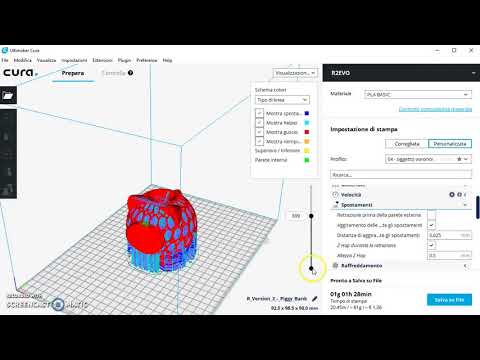
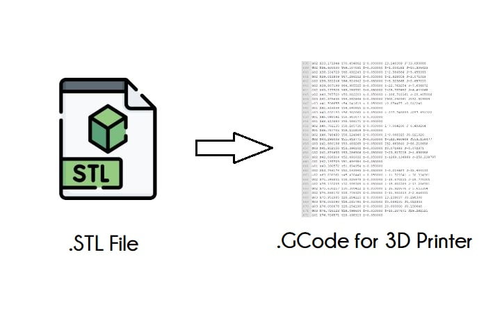
It is created from the 3D model’s STL file using a program known as a “Slicer”. The slicer transforms the STL file into lines of code that tell the printer what to do at every point throughout the printing process.
Do All 3D Printers Use G-Code?
Yes, all 3D printers use G-Code, it is a fundamental part of 3D printing. The main file that 3D models are made from are STL files or Stereolithography files. These 3D models are put through a slicer software to convert into G-Code files which 3D printers can understand.
How Do You Translate & Understand G-Code?
As we said earlier, most of the time, regular users might not even need to edit or modify the G-Code. But sometimes, situations can arise where a user might need to tweak or modify some print settings that can only be found in the printer’s G-Code profile.
In situations like this, knowledge of G-Code can come in handy to help accomplish the task. Let’s go through some common notations in G-Code and what they mean.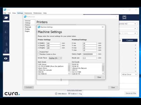
In the G-Code programming language, we have two types of commands; the G command and the M command.
Let’s take a look at both of them:
G Commands
G commands control the different modes of the printer. It is also used in controlling the motion and orientation of the printer’s different parts.
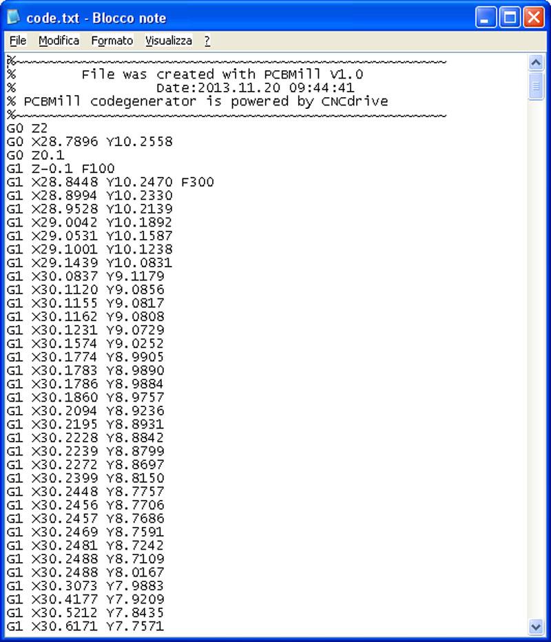
A typical G command looks like this:
11 G1 F90 X197.900 Y30.000 Z76.000 E12.90000; Comment
Let’s go through the line and explain the commands:
- 11 – This indicates the line of code that is running.
- G – The G signifies the line of code is a G command while the number after it represents the printer’s mode.
- F – F is the speed or feed rate of the printer. It sets the feed rate (mm/s or in/s) to the number right after it.
- X/Y/Z – These represent the coordinate system and its positional values.
- E – E is the parameter for the movement of the feeder
- ; – The semi-colon usually precedes a comment on the G-Code. The comment is not part of the executable code.
So, if we put it all together, the line of code tells the printer to move to coordinate [197.900, 30.00, 76.00] at a speed of 90mm/s while extruding 12.900mm of material.
The G1 command means the printer should move in a straight line at the specified feed speed. We’ll look at other various G commands later.
You can visualize and test out your G-Code commands here.
M Commands
M commands differ from G commands in the sense that they start with an M. They control all the other miscellaneous functions of the printer such as the sensors, heaters, fans, and even the printer’s sounds.
We can use M commands to modify and toggle the functions of these components.
A typical M command looks like this:
11 M107; Turn off part cooling fans
12 M84; Disable motors
Let’s decipher what they mean;
- 11, 12 – These are the lines of the code, to be used as a reference.
- M107, M84 – They are typical end of print commands for the printer to power down.
How To Edit G-Code In Cura
As we mentioned earlier, the popular Ultimaker Cura slicer provides some G-Code editing functionality for users. Users can tweak and optimize some parts of the G-Code to their custom specifications.
However, before we get into the editing of G-Code, it’s important to understand the structure of G-Code. G-Code is structured into three main parts.
Initialization Phase
Before printing can start, certain activities need to be carried out. These activities include things like pre-heating the bed, turning on the fans, calibrating the position of the hot end.
All these pre-printing activities are in the initialization phase of the G-Code. They are run before any other code snippet.
An example of initialization phase code is:
G90; set the machine to absolute mode
M82; Interpret extrusion values as absolute values
M106 S0; Power on the fan and set the speed to 0.
M140 S90; Heat the bed temperature to 90oC
M190 S90; Wait until the bed temperature reaches 90oC
Printing Phase
The printing phase covers the actual printing of the 3D model. G-Code in this section controls the layer-by-layer movement of the printer’s hotend, the feed speed, etc.
G1 X96.622 Y100.679 F450; controlled motion in the X-Y plane
G1 X96.601 Y100.660 F450; controlled motion in the X-Y plane
G1 Z0.245 F500; change layer
G1 X96.581 Y100.641 F450; controlled motion in the X-Y plane
G1 X108.562 Y111.625 F450; controlled motion in the X-Y plane
Printer Reset Phase
The G-Code for this phase takes over after the 3D model finishes printing. It includes instructions for cleanup activities to get the printer back to its default state.
An example of printer end or reset G-Code is shown below:
G28; bring the nozzle to home
M104 S0; turn off heaters
M140 S0; turn off bed heaters
M84; disable motors
Now that we know all the different phases or sections of G-Code, let’s look at how we can edit them. Like most other slicers, Cura only supports editing the G-Code in three places:
- At the start of the print during the print initialization phase.
- At the end of the print during the print reset phase.
- In the printing phase, during layer changes.
To edit G-Code in Cura, you have to follow a set of instructions. Let’s go through them:
Step 1: Download Cura from the Ultimaker site here.
Step 2: Install it, agree to all the terms and conditions, and set it up.
Step 3: Add your printer to the list of printers.
Step 4: When setting up your printing profile, instead of selecting Recommended mode to choose the Custom mode.
Step 5: Import your G-Code file into Cura.
- Click preferences
- Click profile
- Then click import to open a window to import the file
Step 6: Alternatively, you can go to the printer’s settings, click machine settings then enter your G-Code manually.
Step 7: In the printer’s settings, you’ll see tabs for modifying the start and end G-Code for various components like the extruder(s), print head settings, etc.
Here, you can modify various print initialization and reset settings. You can edit commands and also add some of your own.
In the next section, we’ll be looking at some of those commands.
You can use also Cura’s post-processing extension to modify your G-code. Here’s how you can do it.
Step 1: Open Cura and load your file.
Step 2: Click on the extensions tab on the toolbar.
Step 3: Click on extensions, then click on modify G-Code.
Step 4: In the new pop-up window, click on “Add scripts”.
Step 5: A menu will show up containing options like “Pause at height”, “Time lapse” etc. You can use these preset scripts to modify your G-Code.
What are Some Common 3D Printer G-Code Commands?
Now that you know all about G-Code and how to modify it in Cura, let’s show you some commands you can use.
Common G Commands
G1 /G0 (Linear Move): They both tell the machine to move from one coordinate to the other at a certain speed. G00 tells the machine to move at its max speed through space to the next coordinate. G01 tells it to move to the next point at a specified speed in a straight line.
G2/ G3 (Arc or Circle Move): They both tell the machine to move in a circular pattern from its starting point to a point specified as an offset from the center. G2 moves the machine clockwise, while G3 moves it in a counter-clockwise pattern.
G28: This command returns the machine to its home position (machine zero) [0,0,0]. You can also specify a series of intermediate points the machine will pass through on its way to zero.
G90: It sets the machine to absolute mode, where all the units are interpreted as absolute coordinates.
G91: It moves the machine several units or increments from its current position.
Common M Commands
M104/109: Both commands are extruder heating commands they both accept an S argument for the desired temperature.
The M104 command starts heating the extruder and resumes running the code immediately. The M109 waits until the extruder reaches the desired temperature before running other lines of code.
M 140/ 190: These commands are bed heating commands. They follow the same syntax as the M104/109
The M140 command starts heating the bed and resumes running the code immediately. The M190 command waits until the bed reaches the desired temperature before running other lines of code.
M106: The M106 command allows you to set the speed of the external cooling fan. It takes an argument S which can range from 0 (off) to 255 (full power).
M82/83: These commands refer to setting your extruder to absolute or relative mode respectively, similar to how G90 and G91 set the positioning for the X, Y & Z axis.
M18/84: You can disable your stepper motors and can even be set with a timer in S (seconds). E.g. M18 S60 – this means disable steppers in 60 seconds.
M107: This allows you to turn off one of your fans, and if no index is given, it will be the part cooling fan.
M117: Set an LCD message across your screen immediately – “M117 Hello World!” to display “Hello World!”
M300: Play a tune on your 3D printer with this command. It uses M300 with an S parameter (Frequency in Hz) and P parameter (Duration in milliseconds).
M500: Save any of your input settings on your 3D printer to EEPROM file to remember.
M501: Load all of your saved settings within your EEPROM file.
M502: Factory reset – reset all configurable settings to factory defaults. You’ll have to save this by also using M500 afterwards.
These commands are just a sample of the wide array of G-Code commands available. You can check out MarlinFW for a list of all the G-Code commands, as well as RepRap.
Best Free G-code Editors for 3D Printing
Cura is great for editing G-Code, but it still has its limitations. It is only useful for editing certain areas of the G-Code.
If you are an advanced user and you need more freedom to edit and work around your G-Code, we recommend using a G-Code editor.
With these editors, you have the freedom to load, edit and even visualize the various areas of your G-Code. Here is a list of some of the most popular free G-Code editors.
Notepad ++
Notepad++ is a juiced-up version of the normal text editor. It can view and edit several file types with G-Code being one of them.
With Notepad, you have standard functionality like search, find and replace, etc to help you in editing your G-Code. You can even unlock additional features like text highlighting by following this simple guide.
Notepad++ might not be the flashiest G-Code editor on the market, but it is quick, easy to use, and lightweight.
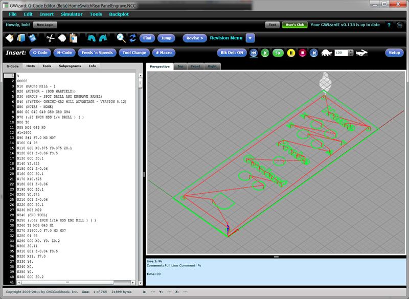
NC Viewer
NC viewer is for users looking for more power and functionality than what Notepad++ has to offer. In addition to powerful G-Code editing tools like text highlighting, NC viewer also provides an interface for visualizing the G-Code.
With this interface, you can go through your G-Code line by line and view what you are editing in real life. It is important to note that this software was not developed with 3D printers in mind. It is geared towards CNC machines, so some commands might not function well.
gCode Viewer
gCode is an online G-Code editor built primarily for 3D printing. In addition to providing interfaces for editing and visualizing G-Code, it also accepts information like nozzle size, material, etc.
With this, you can generate and compare different cost estimates for various G-Codes to determine the optimal version.
Finally, a word of caution. Before you edit your G-Code, make sure you back up the original G-Code file in case you might need to reverse the changes.
Also, make sure you calibrate your printer properly before you start using the G commands. Happy editing.
G-CODE in Russian for 3D printing (Mini-guide)
Often, for high-quality printing, and especially when selecting print parameters, it is necessary to be able to read and edit the G-code during calibration.
A commonplace example: setting your own values for the "Temperature Tower" or creating start and end blocks of codes in slicers for a specific printer.
On some sites (like reprap.org/wiki/G-code) on the Russian-language pages, the commands are only partially described in Russian, and the rest in English. On some domestic sites, the commands are translated into Russian, but some are given with errors - stupidly copy-paste a clumsy translation. nine0003
Tired of searching through different sites, trying to find the CORRECT description of a particular command and its parameters.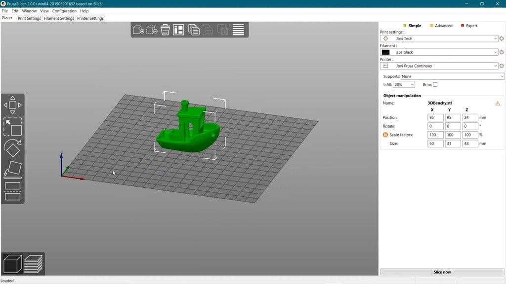
I made myself such a mini-reference book. I'll be glad if anyone else finds it useful.
I tried to describe the maximum number of commands used, except for very specific ones.
(Yes, special commands for deltas, for example, sorry, I consider them specific and not necessary for me)
However, most commands are supported by all printers and firmware.
Attention! Compliance of commands and parameters is checked only for Marlin firmware.
G-commands
G0(G1) Xnnn Ynnn Znnn Ennn Fnnn – movement.
G0 - fast idle
G1 - linear working travel
Xnnn, Ynnn, Znnn – coordinates.
Еnnn - amount of extruded material in mm (with negative values - retract).
Fnnn – travel speed in mm/min (this speed will be used until the next change). nine0003
G0 X12 (will move 12mm in X)
G0 F1500 (Set travel speed to 1500 mm/min.)
G1 X90.6 Y13.8 E22.4 (Move 90.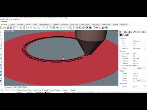 6mm in X and 13.8mm in Y while extruding 22.4mm of material.)
G4 .
Pnnn - Timeout, in milliseconds
Snnn - Timeout in seconds.
"G4 S2" and "G4 P2000" - equivalent to
G10 - Plastic rollback (Retract)
Filament rollback according to M207 settings.
G11 - Plastic feed
Feed / reposition the head according to M208 settings.
G20 - Inch unit setting
G21 - Setting the units in millimeters nine0027
From now on, the reading will be in inches/millimeters.
G28 - Move to start ("home") until limit switches actuate
G28 – home on all axes.
G28 X Z - Move home only in X and Z axes
G29 - Create table curvature mesh (MESH_BED_LEVELING)
The command allows you to create a compensation (Z-height) grid and use it later when printing. The grid can be used repeatedly even after the printer is turned off. nine0003
After using the G28 command, the mesh created by the G29 command flies off.
It is necessary to save the rhinestone mesh after it has been created! To recall the grid from memory, use the M420 command.
Be sure to use G28 before using G29, otherwise the mesh will be incorrect.
Creating Mesh Bed Leveling manually (via commands):
1. Enter G29 S0 to start meshing.
2. Enter G29 S1 to set the first grid point. nine0003
3. Align the nozzle with paper (as usual).
4. Enter G29 S2 to save the value and jump to a new point
5. Repeat steps 3 and 4 until the creation procedure is completed.
6. Enter M500 to write the resulting mesh to EEPROM.
Creating Mesh Bed Leveling using the printer menu (the function must be active in the firmware):
1. Select Prepare followed by Auto home (aka G28 command). nine0003
2. Select Prepare and then Level Bed.
3. Wait for on-screen instructions to begin. Press the "twist" on the screen when the inscription "Click to Begin" appears. The head will go to the first grid point.
4. Use the thumbwheel to raise or lower the nozzle to align the nozzle with the paper. Same as when leveling the table. After you have achieved the desired gap between the nozzle and the piece of paper, press the "twist". The head will move to a new grid point.
5. Repeat step 4 until the program has passed all points. nine0003
6. When finished, enter the Control menu and select the Store memory item to save the created mesh to EEPROM.
To use the grid stored in EEPROM when printing, use the command
M420 S1 (See M420).
G90 - Setting absolute coordinates
All coordinates are absolute relative to the machine origin.
G91 - Set relative coordinates nine0027
All coordinates from now on become relative to the last position. Marlin translates all axes into relative coordinates, including the extruder.
G92 Xnnn Ynnn Znnn Ennn - Set position
This command can be used without any additional parameters.
G92 - reset all axis coordinates to zero.
Xnnn - new X coordinate nine0003
Ynnn - new Y coordinate
Znnn - new Z coordinate
Ennn - new extruder position
Example: G92 X10 E90
M-commands
M17 - Enable/Enable all stepper motors
M18 - Remove current from motors
Motors can be turned by hand. Command analog M84
M20 - List of files on SD card
M21 - SD card initialization
If the SD card is loaded when the printer is turned on, this will happen by default. The SD card must be initialized for other SD card functions to work.
M22 - Release SD card
The specified SD card will be released. On future (random) read attempts, a guaranteed error occurs. Useful before removing the SD card. nine0003
M23 - Select file on SD card
Example: M23 filename.gco
M24 - Start/continue printing from SD card
The printer will print from the file selected with the M23 command.
M25 - SD card print pause
M28 - Start writing to SD card
Example: M28 filename.gco.
A file is created on the SD card, designated as filename.gco (if the file exists, it is overwritten) and all subsequent commands to the printer are written to this file. nine0003
M29 - Stop writing to SD card
Example: M29 filename.gco
The file opened by the M28 command is closed and all subsequent commands are executed by the printer in normal mode.
M30 - Delete file from SD card
Example: M30 filename.gco. filename.gco will be deleted.
M32 - Select file and start printing from SD card
Example: M32 filename.gco.
Used for SD card printing and works the same as M23 and M24
M80 - Enable ATX Power Supply
Puts the ATX power supply into sleep mode. Does not work on electronics without sleep mode.
M81 - Turn off the ATX power supply
M82 - Set the extruder to absolute mode
M83 - Set extruder to relative mode
Allows extruder to be extruder in absolute/relative units
M84 SNNN X, Y, Z, E - transfer motors to the waiting mode of
SNNN - time per seconds.
If a timeout is specified with Snnn, this command simply sets the stepper motor inactivity timeout.
If no motors (X,Y,Z or E) are specified, this command immediately disables all.
If one or more axes are specified, this command disables the specified ones immediately. For example, "M84 S10" will put stepper motors into standby mode after 10 seconds of inactivity.
M92 Xnnn Ynnn Znnn Ennn - Set the number of steps per axis per unit
Ennn - steps per unit for extruder nine0003
Examples: M92 X87.489 Y87.489 Z87.489 or M92 E420
Allows you to set the number of steps per unit (usually mm) for motors. These values are replaced with the values from the firmware at power up unless written to the EEPROM see M500.
M104 Snnn - Set extruder temperature and DO NOT wait
Snnn - Set temperature
Example: M104 S190
Sets the temperature of the active extruder 190C and immediately returns control (that is, DOES NOT WAIT for the extruder to reach the set temperature). See also M109
M105 - Get Extruder Temperature
Gets the temperature of the active extruder and hot bed in degrees Celsius. The temperature is transmitted to the connected computer. The response sent to the computer might look like this: ok T:201 B:117
M106 Snnn - Turn on the fan blowing part
SNNN - fan rotation of fan from 0 to 255 (127 - 50% speed)
m107 - turn off the fan
m108 - cancel the heating 9000 9000 temperature set by M109 and M190, continues printing.
M109 Snnn - Set extruder temperature and wait
Sets the temperature in Celsius and waits for it to be reached. See also M104
M110 Nnnn - Set current line number
Nnnn - Line number
Example: M110 N123
In this example, the number of the current line 123 is set. Thus, it is expected that the next line after this command will be 124.
M112 - Emergency Stop
m114 - receipt of current positions 9
M115 - Get a firmware version
m119 - get the status of ends
m140 - set the temperature of the table and DO NOT wait
Example: M140 S65
Sets the table temperature to 65C and immediately returns control (ie DOES NOT WAIT for the table to reach the set temperature). See also M190
M190 - Set table temperature and wait
Sets the temperature in Celsius and WAITS to reach it. see M140
M200 Dnnn Tnnn - Set the REAL diameter of the filament rod.
Dnnn – diameter in mm.
Tnnn – extruder number. (can be omitted for single extruder printers)
Example: M200 D1.65
Used to calculate the actual extruded volume. nine0003
See M404 for rating setting.
M201 Xnnn Ynnn Znnn Ennn - Setting of the maximum accelerations (in mm/s in sq.)
for axes.
Ennn - accelerations in mm/s in sq. for the extruder.
Only one/two of the parameters can be used.
Example: M201 X1000 Y1000 Z100 E2000
Use M500 to store parameters in EEPROM
M202 - Setting the maximum acceleration for simple (idle) movement.
!Not used in Marlin! V mm/s in sq. Example: M202 X1000 Y1000
M203 Xnnn Ynnn Znnn Ennn - Setting the maximum speed (in mm/s)
Xnnn, Ynnn, Znnn - max speed for axes
Ennn - max extruder speed. nine0003
Only one/two of the parameters can be used.
Example: M203 X6000 Y6000 Z300 E10000
Use M500 to store parameters in EEPROM.
M204 Pnnn Rnnn Tnnn - Acceleration setting (in mm/sec. in sq.)
Pnnn - Printing acceleration
Rnnn – Retract Acceleration
Tnnn - Accelerations during idle movements
Only one/two of the parameters can be used. nine0003
Example: M204 P800 T3000 R9000
Use M500 to store parameters in EEPROM.
M205 Xnnn, Znnn, Ennn - Setting the maximum jerk (jerk) (mm / s)
Xnnn - jerk along the X and Y axes. (Jerks are the same along these axes)
Znnn - jerk along the Z axis.
Ennn - extruder jerk.
Only one/two of the parameters can be used.
Example: M205 X30 Z5 - Set jerk X/Y = 30, Z jerk = 5. nine0003
Use M500 to store parameters in EEPROM.
М206 Xnnn, Ynnn, Znnn - Set offsets relative to limit switches (zero)
Similar to G92 command, but these offsets can be written to EEPROM see M500.
Example: M206 X10.0 Y10.0 Z-0.4
M207 Snnn Fnnn Znnn - Set retract parameters (bar retraction)
Snnn - positive retract value in mm. nine0003
Fnnn – feedrate mm/sec.
Znnn - lift (lift) of the head along the Z axis in mm during retract. (Helps avoid hitting the model)
Example: M207 S4.0 F2400 Z0.075
Used subsequently for G10 and G11 commands.
Use M500 to store parameters in EEPROM.
M208 Snnn Fnnn – Bar feed recovery parameters after retract
Snnn – positive feed value in mm. nine0003
Fnnn – feedrate mm/sec.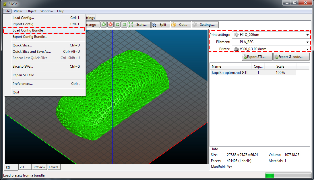
Use M500 to store parameters in EEPROM.
M209 Snnn – On/off automatic retraction
Snnn – value 1 – on, 0 – off
Used if the slicer does not support the G10 and G11 commands.
Each extrusion command will be classified as a retract, depending on the value (positive or negative).
M218 Tnnn Xnnn Ynnn – head offset setting
Tnnn - head number
Xnnn, Ynnn – X,Y coordinates.
Example: M218 T0 X50 Y10.5
M301 Hnnn Pnnn Innn Dnnn — Write hotend PID parameters(!)
Hnnn – extruder number. h2 - the first exruder (hotend).
Pnnn - Proportional gain (Kp)
Innn - Integral factor (Ki) nine0003
Dnnn - Derivative coefficient (Kd)
Example: M301 h2 P1 I2 D3
Use M500 to store parameters in EEPROM.
See M304 for writing table PID.
M302 Snnn - Allow extrusion at Snnn and above.
Snnn - Set temperature
Example: M302 S170 – enable extrusion (turn on the extruder motor) at a nozzle temperature of 170C and above. M302 S0 - extrude at any temperature. nine0003
M303 Ennn Snnn Cnnn - Start PID calibration process for table/hotend
Ennn - E0 hotend, E1 table.
Snnn is the calibration temperature.
Cnnn – number of calibration cycles. More cycles - more precise parameters.
Example M303 E1 C8 S110 – table PID calibration at 110C for 8 cycles.
The PID parameters will be displayed as a string on the terminal screen of a program running in connection with the printer, such as Repetier-Host. nine0003
M304 Pnnn Innn Dnnn - Write table PID parameters(!)
Pnnn - Coefficient proportional (Kp)
Innn - Integral factor (Ki)
Dnnn - Derivative coefficient (Kd)
Example: M301 h2 P1 I2 D3
M301 - without parameters will display the current parameters.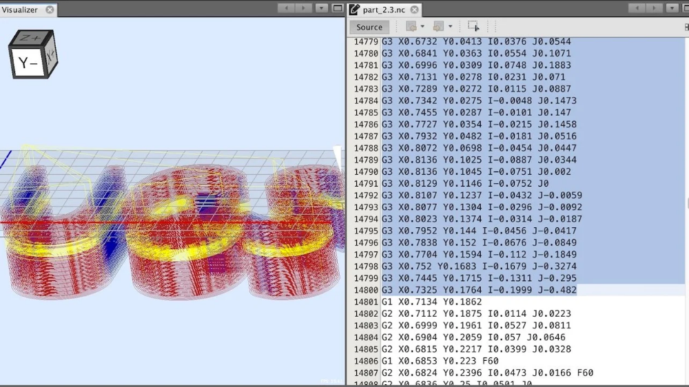
Use M500 to store parameters in EEPROM.
For writing extruder PID see M301. nine0003
М404 Wnnn - Setting the nominal filament thickness 1.75 or 3.
Wnnn - nominal (theoretical) filament thickness in mm.
Example: M404 W1.75
M404 - without parameters, will display the current nominal value as a string.
This value is used to determine the percentage difference in the automatic rate adjustment in response to the measured filament width and must match the value used for the filament width in slicer settings. nine0003
Set actual filament thickness, see M200.
М420 Snnn – Enable/disable the use of the table curvature compensation grid (MESH_BED_LEVELING)
Snnn – S1 on, S0 off.
M420 S1 – use the table curvature compensation grid loaded from EEPROM when printing.
See G29 to get the current status and create a table curvature compensation grid.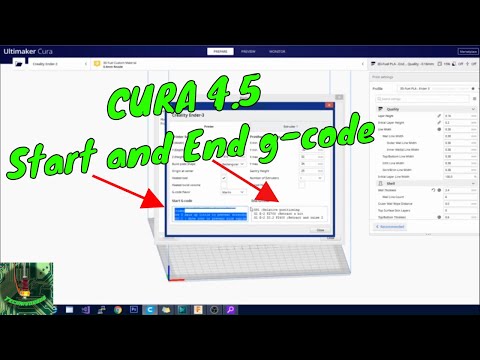
M500 - Save data to EEPROM
M501 - Reading data from EEPROM
M600 - Command for automatic filament change
Simplification of work with a 3D printer using GCode macros
Content
-
- G-CODE structure
- GCode commands
- G-command
- M-Komandrdi
- m-Khomanda printers
- Initial
- Between Layers
- End
- Special
- Cura Macros
- Basic Command Tables
If you look in the dictionary of computer terminology, then a macro (or macro command) is a software algorithm of actions recorded by the user. That is, by definition, the computer must repeat the actions of a person. But in 3D printing, the term has a different meaning. Instead of recording and repeating human actions, the 3D printer will also execute commands, but now they will be written by hand, and not using a slicer.
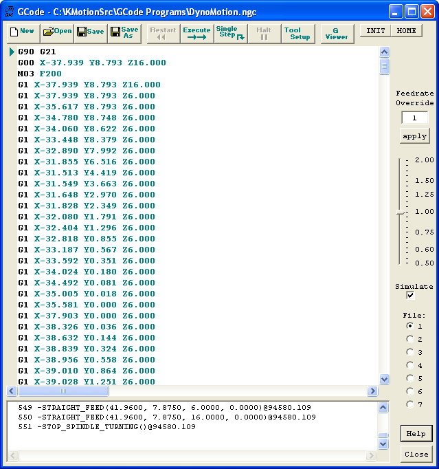 This allows you to directly control the actions of the printer, bypassing the standard way of slicing the model with a slicer. If you look at the GCODE file with notepad or any other text editor, you will see thousands and even tens of thousands of lines with a combination of letters and numbers. It may be scary, but in fact, almost any macro can be written in 5-10 lines. The main thing is to understand the order of writing a separate command. nine0003
 Structure of G-code files
Each GCODE file can be divided into 2 parts: the comment that occurs at the beginning of the program and after the commands, and the commands themselves. Consider the example of a model sliced using PrusaSlicer (Version 2.3.0).
In the first line we are greeted by the name of the slicer, its version, date and time of slicing:
; generated by PrusaSlicer 2.3.0+win64 on 2021-04-22 at 12:31:50 UTC
Please note that at the very beginning of the line there is a semicolon sign, it indicates a comment.
 Everything that is in the line before it is read by the printer, but it does not pay attention to what is after it. nine0003
 Next, we see several lines that show us the line width settings that the slicer used to slice the model. All of them are comments.
; external perimeters extrusion width = 0.45mm
; perimeters extrusion width = 0.45mm
; infill extrusion width = 0.45mm
; solid infill extrusion width = 0.45mm
; top infill extrusion width = 0.40mm nine0003
; first layer extrusion width = 0.40mm
After that there are lines that describe the initial temperatures, the command for finding the zero point of coordinates and the commands for moving. All commands that are involved in the beginning and the process of printing will be discussed further.
Tip: Many slicers, when slicing the GCODE for the printer, leave comments in the file indicating the layer change and / or its number.
 This will help in orienting in commands during manual editing. nine0003
 Gcode command
Many are mistaken, calling this language for the operation of a 3D printer a programming language. In fact, this is a generally accepted format for working with CNC machines, including 3D printers. Each command is on a separate line and represents the name of the command (letter and number) and its parameters (also letters and numbers). For example, a command to move the nozzle to a certain coordinate with plastic extrusion:
G1 X101.912 Y136.607 E2.04825
G1 - team name
X101.912 - X coordinate
Y136.607 - Y coordinate
E2.04825 - amount of extruded plastic
All commands are divided into two main types:
-
G commands
-
M commands
nine0827 - M300 S500 P800
-
Change at Z
-
color mix nine0003
-
Create Thumbnail
-
Filament Change
- nine0002 Retract Continue
-
Search and Replace
-
time lapse
There are other few types, but they are not used in 3D printers, so we will omit them in this article.
G commands
All commands in this group are for movement or calibration. A 3D printer does not use all of them, and not every 3D printer uses the same commands as another. For example, there is a command to auto-calibrate the table. Obviously, if this function is not provided for in your printer by design, then this command will not be executed. Below is a table of the most popular G-commands: nine0003
Command Options Description G0 X - X coordinates
Y - Y coordinates
Z - Z coordinatesMoving without plastic extrusion G1 nine0924X - X coordinates
Y - Y coordinates
Z - Z coordinates
E - amount of pressed plastic (mm)Moving with plastic extrusion G4
S - time in seconds
P - time in millisecondsG28
X-axis X
Y - Y axis
Z - Z axisMoving to zero coordinates.
If parameters are specified, then parking only along the specified axes
G29
The parameters differ depending on the firmware. Automatic construction of a table height map G90
- Transition to absolute coordinate system (all coordinates are relative to zero) G91
nine0925- Change to relative coordinate system (all coordinates are relative to the current position of the nozzle) G92
X - X coordinates
Y - Y coordinates
Z - Z coordinates
E0 - coordinates of extruder No. 0 (amount of extruded plastic)
M commands
These commands are auxiliary. They are mainly related to setting and calibrating temperatures, working with files, and setting up movement parameters.
Command Options Description M17 nine0003
X - motors according to X
Y - Y motors
Z - motors according to Z
E0 - extruder motor No. 0Supply power to all motors if no parameters are specified. Otherwise, only the specified M18 X - motors according to X
Y - Y motors
Z - motors on Z
E0 - extruder motor No. 0Power off on motors
Command reverse M17
M20
- Listing files from an SD card M21
Memory card initialization M22
- Disabling the memory card M23
After the command enter the name of the file Selecting a file from the SD card M24
- Start execution of file selected with M37 M25
- Pausing SD Card Printing M28
After the command enter the name of the file nine0003
A file with the specified name is created or overwritten, all commands that are entered into the printer via a wired connection will be written to it
M29
After the command enter the name of the file
The file with the specified name is saved.
 All further commands are executed as usual. nine0003
 M30
After the command enter the name of the file
Deleting a file with the specified name
M82
-
Switching to absolute mode for the extruder nine0003
M83 - Switching to relative mode for the extruder
M92
X - value on X
Y - Y motors
Z - motors according to Z
E0 - extruder motor No. 0Set the number of steps per millimeter for each specified motor
M104
S - nozzle temperature Set the nozzle temperature without waiting for heating up to the set temperature
M105
-
Print nozzle temperature to console
M106
S - rotation speed (from 0 to 255)
Turn on fan with speed indication
M107 nine0003
-
Turn off the fan
M108
-
Cancel waiting for the nozzle to heat up to the temperature specified in M109 and M190
nine0002 M109 S - nozzle temperature
Set the nozzle temperature and wait for heating to the set temperature
M112
-
Emergency stop:
All heaters turn off
Motors are de-energizedM119
Xn (1/0) - X axis limit switch
1 - invert value
0 - do not invert valueGet the status of the limit switches on the axes, if parameters are not specified
M140
S - table temperature
Set the table temperature without waiting for heating to the set temperature
M190
S - table temperature
nine0002 Set the temperature of the table and wait for heating to the set temperature M200
D - diameter (in millimeters)
T - extruder numberSet filament diameter
M201 X - acceleration for the X axis
Y - acceleration for the Y axis
Z - acceleration for the Z axis
E - extruder accelerationSetting accelerations along the axes
M205
X - jerk for X axis
Y - jerk for Y axis
Z - jerk for the Z axis
E - extruder jerk nine0003Setting the jerk along the axes
M206
X - offset along the X axis
Y - offset along the Y axis
Z - offset along the Z axisSetting the offset relative to the limit switches
nine0002 M300 S - frequency in Hertz
P - duration in milliseconds
Emits a beep at a specified frequency for a specified time
M301
H - heater number
P - coefficient P
I - factor I
D - coefficient DSet the value of PID parameters for a given heater
Some of the above commands can be used before printing to evaluate the status of the printer, such as M20 and M119.
 But many other commands are used to create macros, which we will describe next. nine0003
 Macro types for 3D printers
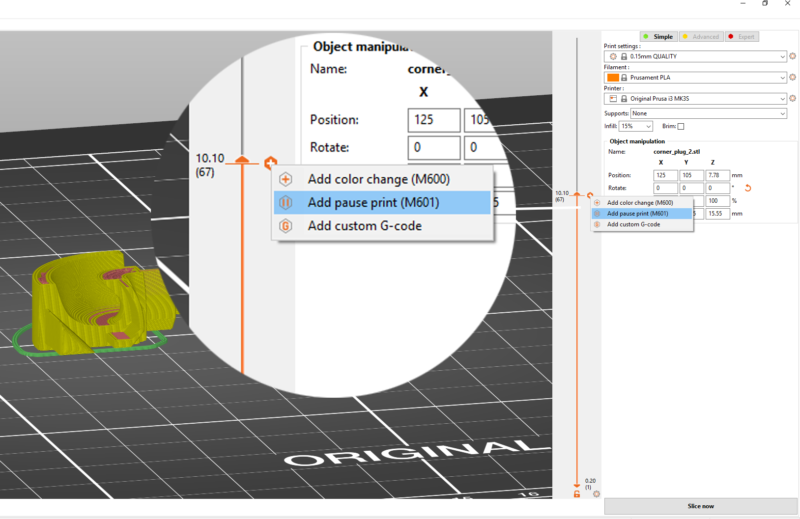
Like any other text document, GCODE files can be edited in notepad. But for this you need to open the file every time, find the desired section and enter your macros. Instead, many slicers offer to manually enter macros, which will then be automatically inserted at the beginning, end or middle of the GCODE file. PrusaSlicer has the most flexibility - you can add a macro in it at the beginning, at the end, before and after layer changes, during a pause and between objects in a sequential print. Next, we will look at the most popular and convenient macros. nine0003
Initial
All macros of this type are designed to prepare the printer before printing. For example, with a single M301 command, you can set the PID on the printer for different temperatures. This can be very important, as the PID depends not only on the characteristics of the printer and its design, but also on the temperature of the print.
 If the hot end is very inert, then the PID values for different temperatures will differ slightly, so it makes no sense to change them every time. But if the hot end has low inertia, then the difference in PID coefficients for different temperatures is large enough to spoil the model due to temperature jumps. You can read more about PID tuning in the article on choosing the print temperature on our website. Once you find the value of the PID parameters for the temperatures you print most often, they can be substituted into the initial GCode. In PrusaSlicer, this can be done in the "Printer Setup" window, inside the "Custom Gcode" tab. nine0003
 For convenience, you can create several printer profiles for different temperatures at once.
Loading filament
If you change the plastic every time you print, then for convenience you can use a small macro to change / refill the filament before printing:
G91; setting the origin relative to the last position
G1 E-100 F2400; Pulling out the filament
G4 S15; Pause for 15 seconds nine0003G1 E100 F2400; Filament loading
G90; Transition to absolute coordinates
G92E0; Setting the extruder coordinate to zero
The value of the E parameter in the two G1 commands must be matched to your printer.
 If you have a bowden extruder, then measure the length of the tube in millimeters and add 30-50 millimeters, then insert the resulting value into parameter E. If you have a direct extruder, you can insert a value of 50-70mm. Paste all the received code into the “Starting G-code” window after the standard commands. nine0003
Attention: after each change, do not forget to save the profile!
Between coats
This group contains macros that directly affect the printing process. They are often the most difficult, due to the need to manually edit the GCode file in notepad or other text editor. But in fact, there is nothing complicated about this, because each such file has comments that make it easy to find the desired section of code. For example, you can add a sound signal when changing layers. To do this, use the M300 command: nine0003
It should be borne in mind that the simplest speaker is installed in the printer, so you should not specify a frequency below 500 Hz, as the sound will be quieter and greatly distorted.
 You can use this site to select the frequency. The square waveform most closely resembles the sound of a speaker. Once you have chosen the appropriate frequency and time, the resulting string can be pasted into the “G-code executed on layer change” window.
 Filament change
This macro allows you to print one model in several colors on a printer that has one extruder. There are only 2 limitations: the color will change exactly at the border between the layers, and with each layer change, you need to manually change the filament.
First you need to determine the place to change the layer. To do this, calculate the height at which the boundary between the layers is located. This is easy to do with the formula:
Layer change height = layer number * layer height (in millimeters). nine0003
After you find the height, you need to open the Gcode file and find the first line in it, which contains the Z parameter with the desired layer height. For example, we need to change the color of the calibration cube on the tenth layer, while we print with a layer height of 0.
 2 mm. So in the Gcode file you need to find the first line where there is Z5. Then, after the comments that the slicer put, you need to insert the following macro:
 G91; transition to relative coordinate system nine0003
G1Z5; raising the nozzle by 5 mm
G90; change to absolute coordinate system
G1 Y10 X10 F1000; moving to the edge of the table
G4 S60; pause 60 seconds (at this time you need to insert the plastic)
G91; transition to relative coordinate system
G1 E100 F100; filling plastic
G92E0; zeroing extruder coordinates
G90; change to absolute coordinate system
In the end, your file should look something like the image below:
If you translate these commands into human language: as soon as the next layer begins, the printer raises the nozzle and moves it to the edge of the table. It then waits 60 seconds for you to replace the plastic. After that, the printer will extrude 100mm of loaded plastic to stabilize the flow and continue printing.
 This command can be inserted several times, but keep in mind: each layer change adds 1-2 minutes to the total print time and requires your active actions. nine0003
 End
All slicers at the end of printing leave standard commands: raising the nozzle, turning off the heaters and blowing. But if several models are printed one after another, then it will take a lot of time to reheat the nozzle and table. To prevent the printer from turning off the heat, you must remove the M104 S0 command from the “Final G-code” window. You can also increase the convenience of working with a 3D printer by adding a macro to play a sound signal at the end of printing. nine0003
Sound notification
To play the end-of-print melody, you must add one or more M300 commands after the standard commands in the End G-code window. For example, you can insert three consecutive beeps:
M300 S1000 P100
M300 S1000 P100
M300 S1000 P100
Or the opening theme from Mario:
M300 S2637 P150
M300 S2637 P150 nine0003
M300 S0 P75
M300 S2637 P300
M300 S2093 P150
M300 S2637 P300
M300 S3135 P300
M300 S0 P300
M300 S1567 P300
Star Wars:
M300 S1396 P166
M300 S1396 P166
M300 S1396 P166
M300 S932 P1000 nine0003
M300 S2793 P1000
M300 S2489 P166
M300 S2349 P166
M300 S2093 P166
M300 S1864 P1000
The Simpsons:
M300 S2093 P562
M300 S2637 P375
M300 S2959 P375
M300 S1760 P187
M300 S3135 P562
M300 S2637 P375 nine0003
M300 S2093 P375
M300 S880 P187
M300 S1479 P187
M300 S1479 P187
M300 S1479 P187
M300 S1567 P750
And even music from Indiana Jones:
M300 S1318 P240
M300 S0 P120
M300 S1396 P120
M300 S1567 P120
M300 S0 P120 nine0003
M300 S2093 P960
M300 S0 P180
M300 S1174 P240
M300 S0 P120
M300 S1318 P120
M300 S1396 P960
M300 S0 P360
M300 S1567 P240
M300 S0 P120
The scope for imagination is huge, so you can come up with your own composition and record it in the form of M300 command sequences.
 nine0003
Interesting fact: the author of the Make Anything channel played a tune from the Nintendo service using a 3D printer. The highlight of this video is the use of not only the speaker on the printer board, but also the sound of motors and even a kind of maracas printed on the same printer.
Special
This group of macros includes exceptional macros that are often inapplicable, but in some situations they can greatly simplify printing. For example, a macro for sequential printing of models. That is, the printer prints a model, then either the printer itself or a person separates the part from the table, and the printer starts printing the next model. This process has many limitations and is extremely difficult to customize specifically for your printer. An example of the execution of this idea can be seen in this video. nine0003
Nozzle cleaning
If the nozzle gets dirty quickly and you are tired of cleaning it, and you don’t have a silicone cover for the hotend, then you can clean the nozzle before each print using a metal brush.
 To do this, you need to fix a metal brush in the far corner of the table, and add the following lines to the initial G-code, after the nozzle heating commands:
 G28; Movement to the origin
G90; change to absolute coordinate system nine0003
G0Z10; raising the nozzle to “Cleaning Height”
G0 Xnnn Ynnn; moving to the far edge of the brush
G0 X(nnn-10) Ynnn; moving to the near edge of the brush
G0 Xnnn Ymmm
G0 X(nnn-10) Ynnn
G0 Xnnn Ymmm
G0 X(nnn-10) Ynnn
G0 Xnnn Ymmm
G0 X(nnn-10) Ynnn
G28; return to origin nine0003
Here, instead of Xnnn and Ynnn, there should be the coordinates at which the far edge of the brush is located. For example, for a 200x200mm table, the movement commands would look like this:
G0 X195 Y195
G0 X185 Y195
The height at which the nozzle will be located must be selected experimentally. It is desirable that the bristles of the brush completely cover the nozzle, but do not interfere with its movement.
nine0002 Attention: the brush must be firmly fixed, otherwise, when it is separated from the table, it can block the movement mechanics and break the motors!
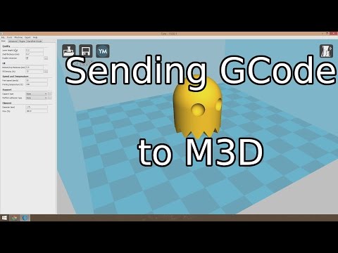
Macros in Cura
Relatively recently, the Cura slicer has acquired the ability to edit Gcode in the program itself. A distinctive advantage of this method is the feedback between the slicer and this function, which allows, for example, to display the remaining print time directly on the printer screen. nine0003
To start working with macros, you need to open the post-processing window. To do this, select the “extensions” tab in the toolbar, then “post-processing” and click “Change G-code”.
A post-processing window will open in front of you. In the left half there will be a list of plugins, on the right the settings of the selected plugin. Working with multiple plugins is similar to working with layers in Photoshop. Scripts will edit the Gcode file in order, meaning a script can affect upstream scripts, but not vice versa.
 nine0003
 The following is a list of scripts and their brief description:
This script allows you to change the speed, temperature, flow and blowing power at a certain height. The values are applied to all subsequent layers. You can also choose to display changes on the printer screen. Basically the script is used to print test models.
This script is for mixing extruders (eg A10M from Geeetech). Unlike just two-color printing, this extruder can mix two plastics, which allows you to create transitional shades.
Create icons for Ultimaker Format Package (.ufp) files. Used when implementing a slicer in Octoprint. nine0003
The name speaks for itself: displaying the file name and layer number on the screen.
Displaying the remaining print time on the printer screen
Automate the Gcode editing process for changing filament.
It is an analogue of the Gcode insertion windows when changing the layer in PrusaSlicer
Allows you to add recoil during nozzle movement between parts of the model
Removes the specified characters and replaces them. If replaced with a space character, then this script simply removes the specified characters
This script helps in creating high-quality time-lapses using the camera. At each layer, the printer will move the carriage to the side and send a command that can activate the camera.
If your printer has the ability to build a table height map, then this script will replace the repeated height measurement with the result of previous measurements.
The most commonly used and useful plugins are Change At Z and Search and Replace. They cover 80% of all required changes in Gcode.
 Therefore, even if you are not going to use them in the near future, it is still better to study them at least at a superficial level. nine0003
 Basic command tables
When servicing the printer, the final step in checking and setting up is to self-diagnose the printer and check it in operation. But not all actions can be done from the printer menu. For convenience, we have collected all the necessary commands in one small table that you can quickly open and use.
Command Options Description nine0917 G28
X-axis X
Y - Y axis
Z - Z axisMoving to zero coordinates.
If parameters are specified, then parking only along the specified axes
M92
nine0925X - value on X
Y - Y motors
Z - motors according to Z
E0 - extruder motor No.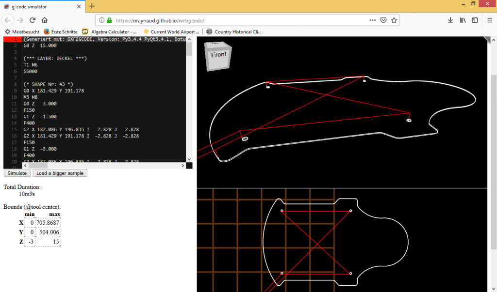 0
0 Set the number of steps per millimeter for each specified motor
M303
S - temperature
C - number of cycles nine0003PID autotuning command. The more cycles, the higher the accuracy
M301
H - heater number
P - coefficient P
I - factor I
D - coefficient DSet the value of PID parameters for a given heater nine0003
M112
-
Emergency stop:
All heaters turn off
Motors are de-energizedATTENTION! If the printer gives an extruder or bed heating error, then the M112 command may not fix the problem, as often this error occurs when the transistors / relays are “jammed” or shorted! It is better to immediately turn off the power to the printer, and then find out the cause of the error.
Learn more