Diy handheld 3d scanner
How to Build Your Own Custom Handheld 3D Scanning Kit
8/26/2020
8 Comments
Customize the right 3D scanner for your needs! With the hardware and software options continuing to grow, it's time for a review of the step-by-step process to set up your ideal kit:
1. Choose your tablet / phone:
The first step is to select a tablet or phone for use with your 3D scanning hardware and software. If you already own a compatible device, you're one step ahead! Just please make sure that your device meets all the minimum specs required, including a USB 3.0+ port.
| Microsoft Surface Go 3 | Samsung Galaxy Tab S8 | Android Phones |
| Microsoft Surface Pro | Rugged Tablets | Other Compatible Devices |
2. Choose your 3D depth camera (or multiple!):
Each option offers unique benefits in terms of accuracy, price, range, daylight capability, size, compatibility, etc., so often times it may make sense to equip a kit with multiple cameras. Please click here for a more in-depth list of all the currently supported offerings.
| DPI-10 / DPI-X Kit | DPI-10SR / DPI-XSR Kit |
| Depth Camera D455 | Depth Camera D415 | Depth Camera D435 / D435i |
3. Choose your 3D scanning app:
In our humble opinion, the most important part! Activate Dot3D Pro, X, or Lite on your tablet/phone to complete the package and enable instant 3D capture and editing capabilities. Please click here to download Dot3D, and here to subscribe to your preferred version.
| Dot3D™ Pro | Dot3D™ X | Dot3D™ Lite |
CLICK HERE TO COMPARE THE Options
4. Consider any applicable accessories and add-ons:
You may also want to consider some of the following optional accessories for scanning in the dark, extended reach, data processing, 3D meshing, scale bar targeting, rugged protection, etc.
| RealSense™ Mounting Kit | DPI Light Kit | DPI Extension Kit |
| Dot3D™ Edit | Pointfuse for DP | iOgrapher Multi Case |
| AccuScale-DP Scale Bar Kit | Rugged Tablet/Phone Cases | Dot3D™ View |
In summary, you now have all the options at your disposal! Get up and running on a compatible device for as low as $500 with a D415 and Dot3D Lite, purchase a complete DPI-10 Kit with a perpetual license and tablet included for only $5795, or explore the many options in between to assemble the ideal kit for your projects. We expect to see continued evolution of these offerings and more, so please stay tuned for updates to this guide, as well as a new video series outlining the steps to assemble your kit on a variety of platforms.
8 Comments
6 DIY 3D Scanners You Can Build at Home
Creating a 3D model of a real object can be done extremely fast if you have a 3D scanner at home. The problem is: 3D scanners are expensive to buy new.
If you're looking for a solution, why not try building your own affordable 3D scanner at home? It might not create perfect 3D models, but it's a cost-effective alternative to buying a 3D scanner.
Is It Cheaper to Build a DIY 3D Scanner?
The cost of buying a decent 3D scanner ranges from $700 to $10,000 at the highest end. On the other hand, building a DIY 3D scanner can cost less than $200—some even as little as $35.
Depending on the resolution of your homemade 3D scanner, you will still have to work to tidy up the 3D model so that it can be used for things like 3D printing, game development, or perhaps design prototyping. But overall, it will still speed up the design process when compared to building a model from scratch.
1. Cheap 3D Printed 3D Scanner
This 3D scanner is built using 3D printed parts, featuring both open source software and open source hardware files. If you choose to install the maximum of four lasers, then the cost of the project comes in at $35 to $50. Once it's built, handling the digital scan will require some legwork to smooth out. But considering its price tag, it's well worth giving it a go.
You can find the STL files and a full build guide on Instructables. Besides the 3D printed components, you will need one to four lasers, a stepper motor, a turntable, and an Arduino Nano to bring it all together. One benefit of this project is that it's been built many times by community makers, resulting in plenty of images and feedback surrounding the project to help fill in any gaps.
2. DIY 3D Scanner Using a DSLR Camera
Another option for building a 3D scanner is to use a DSLR camera and a method called photogrammetry. At its most basic, it involves taking a lot of images of an object from different angles and stitching those photos together in a software program to create a 3D model.
Alongside a DSLR camera, you will need an Arduino, a stepper motor and driver, an LCD screen, and an IR LED. The goal of the hardware is to build a rotating platform that moves by set amounts so that your camera can photograph the object in a very detailed and controlled way. You can find a great explanation of the project on Instructables.
The real difficulty of this project comes in processing the photos. A good photogrammetry program is essential, and that can cost over $150 to license. There is some free software available, but it may come with limitations.
If you're wondering if there is an alternative solution, you can read our guide to how to turn everyday objects into 3D models without a 3D scanner.
3. Optical CT/3D Scanner With Arduino
For something a little different, in this project you will build a 3D scanner that also doubles as an optical CT scanner. This type of scanner will do the trick if you have objects that are semi-transparent, like a gummy bear or a segment of orange. Otherwise, you can use this setup with the photogrammetry method for regular 3D scans.
Everything in this build is enclosed inside a box. This allows greater control over lighting the object to produce sharper images. While it involves some woodworking and construction, the hardware is still powered by a humble Arduino Nano, plus additional parts that you can find at any hardware store.
A great guide is available on Instructables for building the box, alongside details for creating a sleek control panel for changing photo parameters on the go.
4. FabScan: Raspberry Pi + Arduino 3D Scanner
This 3D scanner uses both a Raspberry Pi and an Arduino to build a 3D laser scanner. What sets this build apart is that it can be operated remotely via a web browser on a phone.
Much like other DIY 3D scanners, a stepper motor and driver are used to rotate a turntable holding the object you want to scan.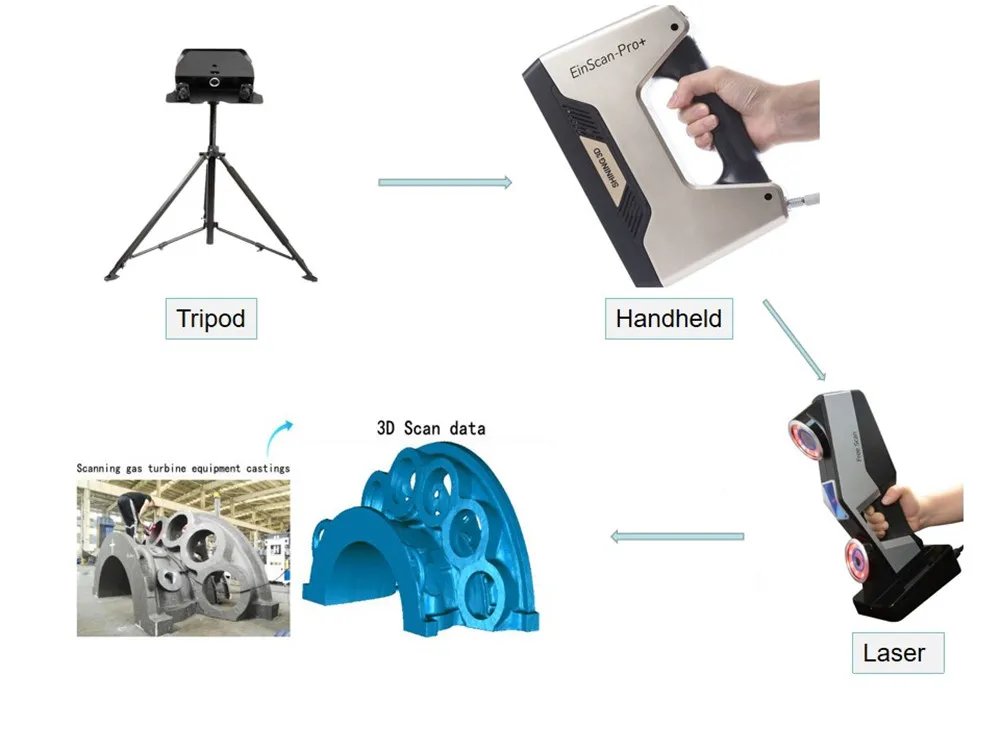 Additionally, you will need a line laser and a Raspberry Pi camera. You can find the guide and a full components list on Instructables.
While the creators have gone with a laser-cut MDF box, you can just as easily use spare parts lying around the home to create the enclosure. Alternatively, cardboard can work too, and painting it black will aid in diffusing the laser light so that it doesn't interfere with the scan.
Once you have a good scan of your object, you might be interested in 3D printing it. Haven't got a 3D printer? Here is our pick of the best 3D printers.
5. The Ultimate Human Sized 3D Scanner With Raspberry Pi
While most homemade 3D scanners are built to capture a small object, it's also possible to build a human-sized 3D scanner. The way to do this is with a lot of Raspberry Pis, as you can see over on Instructables.
The maker behind this project scaled up his 3D scanner using a whopping 47 Raspberry Pis plus a Raspberry Pi camera for each module.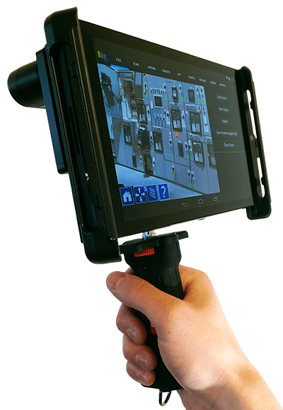 The goal was to use the photogrammetry method to take a photo of his subject from every possible angle. Because he wanted to capture a 3D model of his two-year-old son, this all had to happen instantly.
Incredibly, it works, and it works very well too. If you have the time and investment to buy a box full of Raspberry Pis, you won't be disappointed because the results are impressive. The maker says you can use fewer Pis and cameras and still get good results, especially if you only need to capture the front of a person’s face.
6. Standalone 3D Scanner
Maybe you're just after a simple and small 3D scanner that you can make over the weekend. If so, then this project will suit you. This 3D scanner on Instructables is designed to be all-in-one, meaning that the photos are compiled onboard and an STL file is saved directly to a memory card. Instead of compiling the photos in a separate photogrammetry program, this 3D scanner handles them for you.
While it doesn't produce incredibly detailed scans, it does make for a rapid way to take a 3D model straight to 3D printing.![]() One thing to bear in mind, however, is that the dimensions of the 3D scanner structure need to be kept exactly as written in order to match the code.
One thing to bear in mind, however, is that the dimensions of the 3D scanner structure need to be kept exactly as written in order to match the code.
Building a Homemade 3D Scanner
Putting together a 3D scanner at home isn't extremely difficult to achieve. When compared to the expensive price of commercial 3D scanners, it's well worth building a DIY 3D scanner yourself.
With a Raspberry Pi or Arduino and a few extra affordable parts, you'll be well on your way to creating a cheap and awesome 3D scanner.
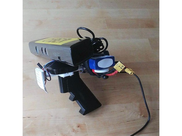
DIY handheld laser scanner, assemble the case!
Hello everyone!
A handheld laser scanner has always been a dream. But for a long time I could not even imagine that I would get my hands on something like Creaform HandySCAN or Shining Einscan...
Suddenly, a few months ago, a proposal from the Russian company Volume Technologies appeared for self-assembly of a laser handheld scanner according to a finished project. This is a company widely known in narrow circles that makes Range Vision level scanners, but operates according to a different business model, more than 10 years of experience in the development of 3D scanning technologies and the production of modern equipment based on them for use in production, in professional activities in the field of education. nine0003
https://volumetechnologies.ru/vt_laser
As I build the scanner, I will share my thoughts, suggestions and additions.
Assembling the Case.
The project contains both ready-made gcode for printing on Picaso and Anycubic Viper (04 nozzle, PETG, suitable for all Ender 3 clones with a bowden extruder) and separate STL for printing on any printer.
Prepared GCODE allows you to get the desired print without much trouble. nine0003
The project also contains useful recommendations regarding 3D printing of parts.
The body of the scanner is printed from black PET-G plastic on an FDM printer, nozzle 0.3 or 0.4 mm, layer 0.2 mm. The first layer is a PrusiaSlicer Hilbert Fill Curve which, when printed on glass, produces a very high quality glossy surface. Before printing on glass, a layer of 3d glue is applied on a cold, folded non-woven cloth in one pass. After the glue spreads and dries, with the formation of a thin glossy film, the table is turned on for heating and printing starts.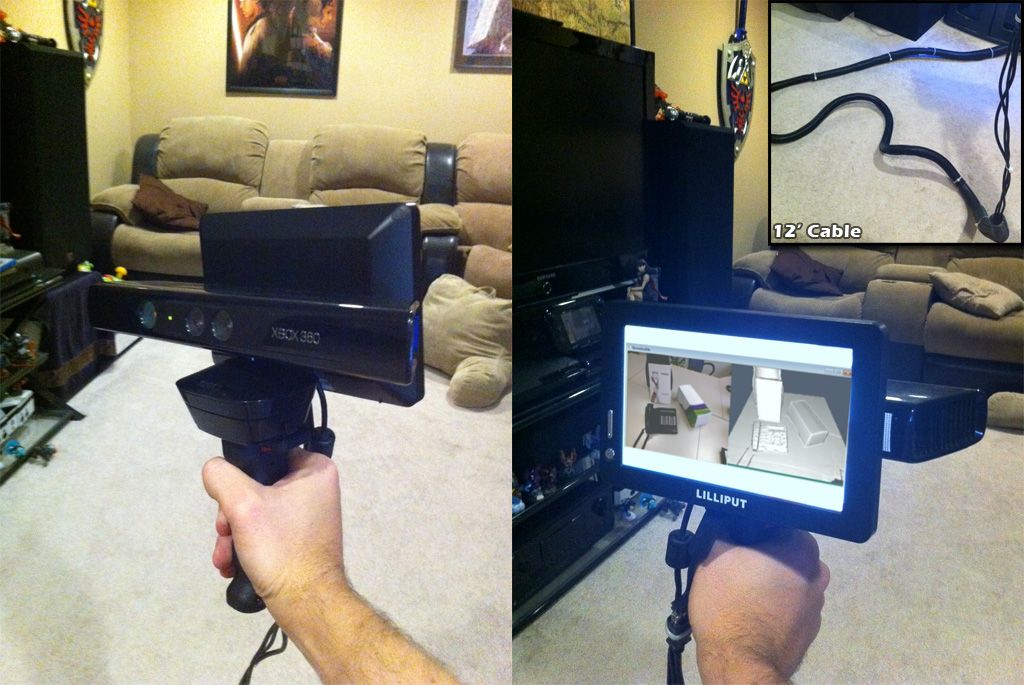 After printing, the parts are washed from 3d glue in water. The buttons are printed with a change of material - the bottom is made of transparent PET-G, the top is made of black PET-G. The insert between the buttons is made of transparent PET-G. The inscriptions on the case are applied by laser engraving, on our plastic we get even white letters on a black background. nine0032
It was interesting to read about the Gilbert curve) But I print on several printers with a 06 nozzle in Kure, it didn’t work out to make friends with Pryuschaslicer, so we use what we have.
In the folders for picaso there is both a layout in the chicken parts, from where you can understand how much and what you need to print, as well as individual parts and Gcode.
In addition to all this, CAD files for the body are available, which can be used for printing if necessary.
I printed flat sidewall parts on ultrabase 02 layer. When printing, there are a lot of movements and retracts, I caught failures several times, the nozzle clogged.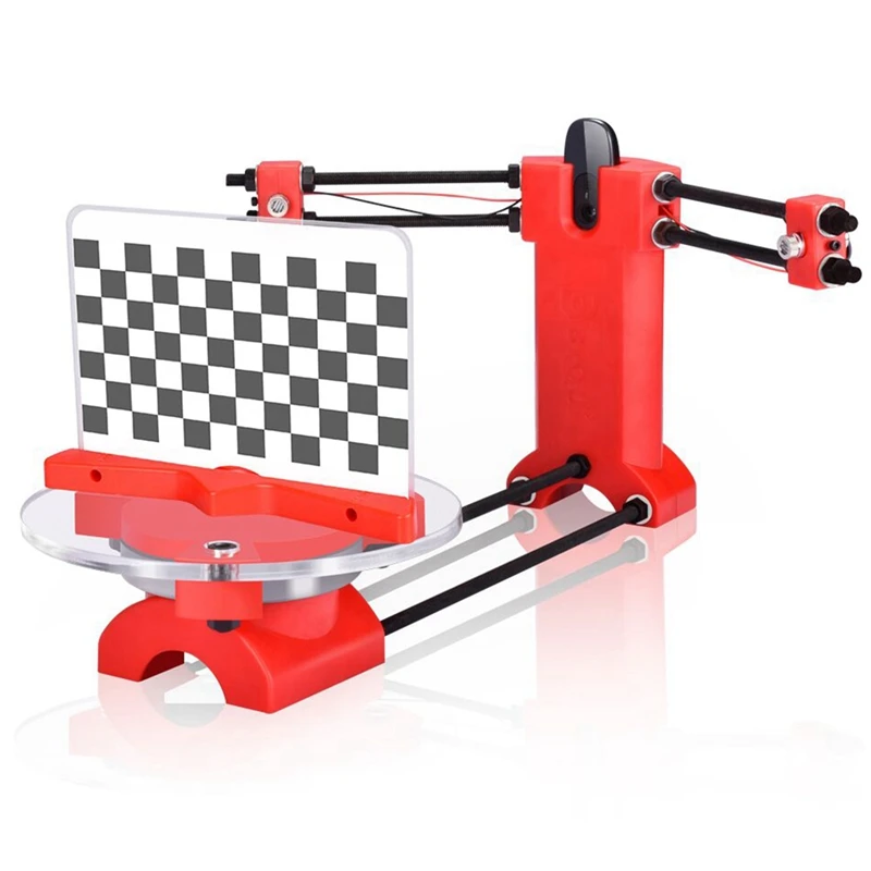 In general, I recommend lifting during retraction, temperature and airflow calibration, reasonable speeds.
Pen parts already come with pre-installed supports in the right places, the slicer will offer additional supports, we print without them.
Some of the parts need to be bent after printing to fit into the case. There are no recommendations in the instructions on this matter, but if you heat it up to 80-9 on the printer table0 degrees and bend, then my parts are bent in the center. In addition, the bending radius came out quite large. After several tests, among which were attempts to bend a cold product and the part simply burst, I came up with the following algorithm. The knife heats up, leans against the attachment point, and while the line is heated, the part bends along it by eye at 45 degrees. The angle turns out to be sharper, the plane does not bend. But based on the results of this work, I recommend printing the part from the CAD model already in the desired folded form or on FDM with supports or on a photopolymer printer.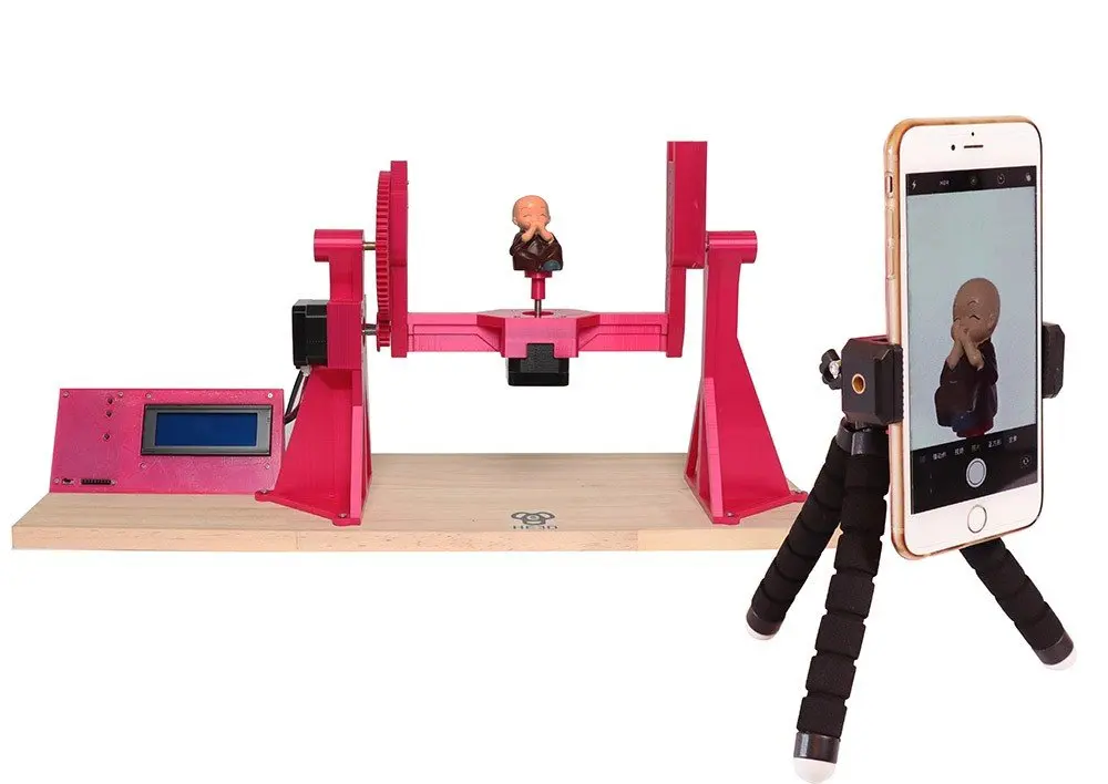 nine0003
Printing a mirror surface did not work) Therefore, I decided to experimentally blow out the case with liquid rubber.
I bought cheap tires and blew them out a few times. It turned out well. The surface is pleasant, matte, soft touch. Of the minuses, cheap liquid rubber is applied in a very thin layer, the cans were enough for literally several layers on the entire body. The scent is strong and takes a long time to dry. The next day, it still sticks to the hand.
Before assembling on self-tapping screws, we go through all the holes with a 2.4 mm drill, quickly assemble on black M2.6x12 screws for fitting
Case ready!
What's left?
A very simple project. Everything is as accessible as possible and prepared in advance. In the event of a breakdown, all parts can be replaced. Greater freedom for creativity and refinement of the case.
Not able or willing to print? - order ready! VT sells finished parts for a reasonable price.
In the future, if the body is modified, I would print the entire body on a medium format photopolymer type Mono X, all parts fit on the table, you can complicate the forms and make the design close to Creaform and Shining. After a minimum layer of liquid rubber, the part looks like a factory one)
How to buy?
Use promo code "Prim3D" and get a bonus when ordering.
Information on the project can be obtained from the following contacts:
Phone: +7 (495) 127-02-47
e-mail: [email protected]
Almost DIY 3d scanner for home / Sudo Null IT News high-quality scanning is out of the question. nine0003
But the main plus that I took out from the article is the David-3D scanning program, which really has a good manual in Russian and, importantly, buying a license is the last thing required, since the free version is limited only to saving the scan result. Everything else works in full, which means that it is quite possible to test the program, settings and your hardware as much as you like. And if you don’t need the result with high accuracy, then you can do without buying a license at all. nine0089
I needed accuracy, since the main thing I wanted to scan was miniatures from the Warhammer board game (so that later I could change them as I wanted and print them :)). The height of these "soldiers" is only 3 cm, but this does not prevent them from being very detailed.
If you do not need to shoot such small objects, then your equipment requirements will be lower, which means that it will be much easier to assemble a similar scanner for yourself.
The principle of the program, and accordingly scanning, is well described in the article, which was linked above (I think it is not necessary to duplicate this). It is advisable to read that article first, as this one will be in some way its logical continuation. nine0003
But let's start in order. What you need to try 3D scanning at home:
1 - projector.
2 - webcam.
That's all, the short list turned out surprisingly well. However, if you want to get very accurate and high-quality scans, then you will have to modify some things with pens. Of course, you can’t do without additional costs, but in the end it will still cost less than buying any of the commercially available 3D scanners, and the quality of the result can be obtained much better. nine0003
Now, in order and in detail.
PROJECTOR.
I, like the author of the previous article, started my first experiments on scanning with a laser pointer, but they immediately showed how inconvenient this method is. There are several disadvantages here at once:
- the impossibility of obtaining a beam with a sufficiently thin line. Moreover, when you turn the pointer, the distance from the lens to the object changes, which means the focus is lost.
- if you need to scan regularly, turn the laser pointer with sufficient accuracy and smoothness by hand is very difficult, and tiringly easy - the hands are not such a stable tool when it comes to a long time. nine0089 - you have to scan in the dark so that only the laser line is visible and nothing more.
And if the second drawback can still be dealt with by creating a special rotary mechanism (although this is already not such an easy task, in any case, this cannot be done in 5 minutes on the knee), then getting rid of the first drawback is more expensive.
When I realized all this, I decided to try scanning with a projector, for which I borrowed some simple model from a friend. nine0003
A small clarification should be made here - in the last article the author mentioned the possibility of scanning with a projector, although the proposal was, in my opinion, very strange -
A projector with a powerful lamp will do, the light of which must be directed through a narrow slit to the object being scanned
This may have been the only option in earlier versions of the program, but in version 3 that I experimented with, the projector was used much better, because there's a feature called Structured Light Scanning (SLS). Unlike laser scanning, the projector immediately projects a grid of vertical and horizontal lines of various thicknesses onto the object, which reduces the scanning time by an order of magnitude and allows you to automatically shoot the color texture of the object. Well, with good focus, a 1 pixel wide line is much thinner than you can get from an inexpensive laser pointer. nine0003
Unfortunately, I didn’t take pictures from those first experiments, and there wasn’t much to take pictures of - the projector is on the table, next to it is a webcam, all of this looks in one direction :) However, even such a simple design showed that this option much better both in terms of scanning speed and quality. Then I decided to buy myself a projector for these purposes.
The criteria for choosing a projector were simple - higher resolution, lower price and dimensions :)
The choice settled on IconBit Tbright x100 - an ultra-compact DLP LED projector, 1080 resolution - at that time it seemed to me that you couldn’t imagine better, but as it turned out later, I was wrong, although while working with it, I got a lot of interesting experience. nine0003
The first problem that occurs when scanning a small object with a projector is that for best results, the size of the projected grid should roughly match the size of the object being scanned. This projector made it possible to obtain the smallest screen diagonal at the closest focus - about 22 cm. Agree that against such a background, a miniature 3 cm high is far from the concept of "approximately equal sizes." The answer was found on the official forum - people in such cases install camera lenses on the projector for macro photography. Given the small size of the projector lens, I opted for marumi lenses with a thread diameter of 34mm. nine0003
Using two of these kits, I managed to get a projector screen with a diagonal of only about 3 cm. Which turned out to be quite enough to make my first microscan -
This is a single scan, therefore there are “holes” on the model, torn edges and etc. By turning the coin and scanning from different angles, you can get several of these scans, which are subsequently combined into one object (the scanning program itself allows you to correctly combine different scans, stitch them together and save them as a single object). In the process of stitching, the shape of the object is also specified. But saving the results of such stitching is possible only after purchasing a license. nine0003
And now the moment has come for the first thing that is not necessary for scanning, but with it the process is much more convenient - this is a stand for a projector with a camera. The calibration process itself is needed not only for the program to recognize the parameters of the equipment - the software must also calculate the relative position of the camera and the projector. In the course of work, their change is not allowed (as well as changing the focus of the camera), which means that it is necessary to firmly fix all this, because the number of scans can be large even for one object. nine0003
David's main page shows a similar system - it is nothing complicated. Yes, and looking through the forum and seeing how different people organize it for themselves, I realized that nothing complicated is required here.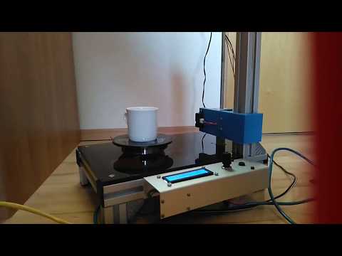
For these purposes, a stand was taken from a burned-out LCD monitor, and plexiglass from it, cut and glued like this design, as it looked in the first version , which allowed changing the screen diagonal and scanning objects of different sizes. nine0089 It should also be mentioned that scanning with a projector does not require the constant presence of calibration panels in the field of view. After the calibration is done, they can be removed. This allows, having calibrated the installation, to easily transfer it, move it, etc.
That is, you can use a large calibration template to calibrate at home on the walls, and then go outside with this stand and laptop and scan your car, for example. We took a smaller template, put a couple of lenses - and you can scan jewelry. nine0003
Recently, the company has released an improved scanning kit, here the stand looks much more serious and interesting -
2000 euros is not entirely justified, it is not difficult to assemble something like this yourself and much cheaper.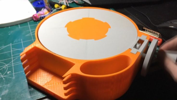
Let's go back to the projector. As it turned out, this projector had one major disadvantage for being used in a scanner, namely its native resolution (854*480). And everything would be fine if it produced the same output, but alas, the picture was converted to standard resolutions (such as 1024 * 768), and as a result, a line one pixel wide was somewhere brighter in different parts of the screen, where - something dimmer, somewhere already and somewhere wider ... All this had a negative effect on the quality of scanning, expressed in the form of ripples and stripes on the resulting model. nine0089 By that time, I was already thinking about buying a projector for a stereolithographic 3D printer (http://geektimes.ru/post/245590/). After considering several options, I settled on the Acer P1500 model, because. it does not need any modifications to be used in a printer (this projector, without any lenses, is able to give a focused image on a screen of about 4 * 7 cm). So, for the scanner, it will fit perfectly.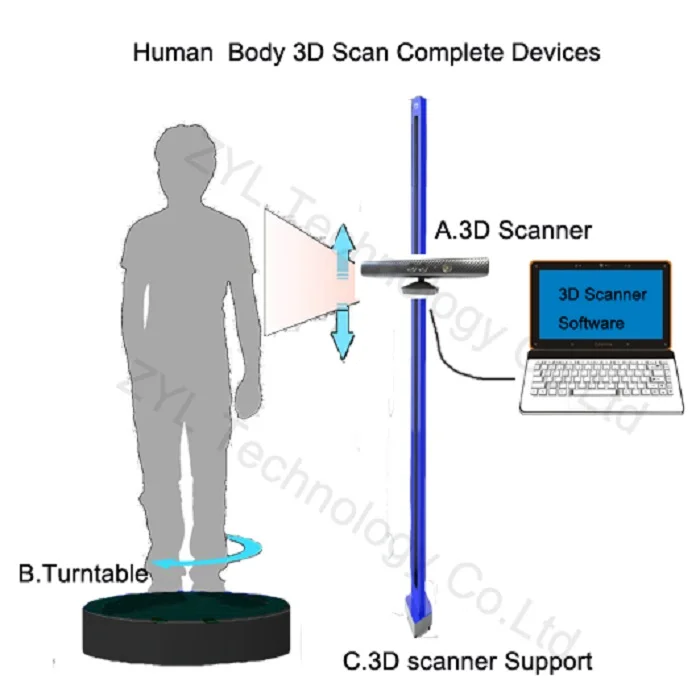 At the same time, the resolution of 1920 * 1080 is real. And so it happened, I still use this projector and am completely satisfied with the results. nine0003
CAMERA.
The criteria for choosing a camera were the same as when choosing a projector. Having gone shopping, I stopped at the Logitech C615. The scan of the coin was made from it, without any modifications. But when I tried to scan the figurine, I ran into a problem called "depth of field". When the object is so small, then in fact we get macro photography, and sharpness with such shooting is achieved only in a small segment, literally just a couple of millimeters (which is why the coin was scanned well - the relief fit perfectly into the sharpness area). It was decided to convert the camera to a different lens. Several different lenses were ordered on Ebay for testing, and a new case was cut out for the camera board. The plan was like this0003
The final result was slightly different
The main idea, I think, is clear. And now, both on Thingiverse and on the forum of the program, you can download stl for printing cases for different types of webcams.
I had to remove the standard lens from the camera board, and as it turned out later, the IR filter was removed along with it, so be careful in this matter. The filter will then come in handy for use with other lenses, although you can buy them separately - the price is cheap. nine0003
Thus, I have formed such a collection of lenses.
While I was waiting for the lenses to arrive, I was reading various photography forums. Studying the issue with depth of field, I found out that you can increase it by closing the lens aperture more. This means that the lens was required one in which it was possible to adjust the aperture (alas, among those ordered, not everyone had such an opportunity, but luckily I got a couple of them). In general, to improve the camera, it is desirable to have a varifocal lens with a zoom and an adjustable aperture. In practice, everything turned out the way it was in theory - closing the aperture, an increase in the depth of field was immediately visible, which made it possible to scan three-dimensional, but small objects. nine0003
The main lens I use is mounted on the camera in the photo above. The second, with an adjustable aperture, is the largest, in the center. I use it for very very small objects. The rest are without a diaphragm, so I don’t use them - it turned out that these two were quite enough.
Now I plan to either find a webcam with a higher resolution (the quality and detail of the scans directly depends on the resolution of the camera), or try to use some digital camera for this purpose with the ability to shoot video - usually you can get a lot more resolution in them, and lenses are better. nine0003
Actually, this could be the end - it seems that he told about everything. I also thought that this was the end of my scanner assembly, but the farther into the forest . .. While studying the forum of this program, I often came across various schemes of turntables - fortunately, the software allows you to automate the scanning process. After one scan, a command is sent to the com port, the turntable rotates, turning the object by a given number of degrees, and gives a command to the next scan. As a result, with one click of the mouse, we have circular scans of the object - it would seem, what more could you want? I tried this system with interest, but alas, I absolutely did not like this approach, and there are a couple of reasons for this. nine0003
1 – if the object has a complex shape, then simply rotating it will not be enough – you also need to tilt it in different directions so that the camera with the projector reaches all the depressions and other hard-to-reach places.
2 - even if there are no such places, and considering all the scans that were made, there are no parts left on the object that did not fall into the scan, the question of the accuracy of the scan remains.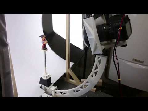
Let's say that some part of the model on one of the scans came out perfectly. But this does not mean that on all the scans in which this part fell, it also looks perfect, and when stitching scans from different angles, the result will be averaged, which cannot please. The program allows you to slightly edit the received scans (you can cut out the unnecessary part). If we rotate the model by 20 degrees, then after a full rotation we will have 18 scans, the part we need may well be present on half of them, therefore, in order to leave the best result, we will need to remove this piece from 8 scans ... And such pieces with a complex There can be many models, as a result, almost half will be cut off from each scan, which is very laborious and time consuming. nine0003
Instead, it is better to immediately scan adjacent areas after the first scan and check the result. As soon as a piece is ready, we move on to scanning the next one, and so on, until the entire model is in perfect shape.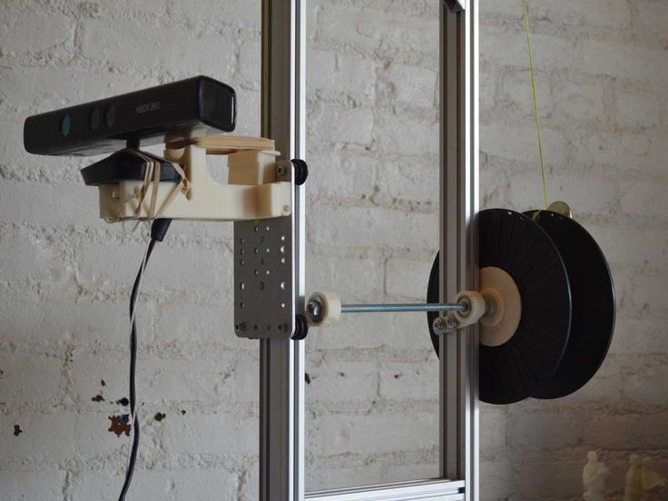 This approach gives the best results in less time.
But the question of convenience arises. Agree, it’s inconvenient to manually try to rotate an object, looking not at it, but at the monitor - in order to control the hit on the lens without changing the distance to the camera and the projector at the same time (so as not to lose focus). With the next similar balancing act, I accidentally touched the camera, which accordingly knocked down the entire calibration, and the whole process had to be started anew. I categorically did not like this alignment, and after some thought I came up with a plan for such a design (which, as you understand, I subsequently assembled). nine0003
This is not a turntable in the usual sense of the term. Thanks to this design, I can not only rotate the model, but also tilt it as I need. In this case, the center of the model remains in the plane of focus, but even if not, you can move the mount with the model back and forth.
All this was assembled on arduino, a small control program was written, and as a result, now I don’t have to get up from the computer when scanning - using the program, I change the position of the object being scanned, and at the same time, right there, in the window cameras I choose the best angle for scanning. nine0003
Insides
In the program, I put the possibility of automatic scanning, as well as scanning is not easy in a circle, but with inclinations of 45 degrees in one direction and the other, which gives three times more scans. Nevertheless, in the end, I still never use this opportunity - it's too inconvenient to sort through the resulting pile of scans and clean them from unsuccessful pieces.
We should also mention some nuances of scanning.
1 - it is impossible to scan shiny and mirror surfaces. The light from them is reflected, or gives such a glare that the program cannot correctly recognize the line. If there is a need to scan such an object, then such parts will have to be masked with something (washable paint, paper tape, etc.). nine0089 2 - it is more convenient to scan monotonous objects, since when the camera is set to a light color, the projector's brightness is not so high, the exposure is low, etc. And a dark-colored object needs more brightness, so if you have a multi-colored object, then different parts of it require different settings to get the best result. Here, too, it is more convenient to use scanning the object in parts.
3 - if you want to immediately get a color texture, then please note that the settings of the camera and the projector for scanning do not affect the settings for removing the texture (the scan is generally done in black and white mode), so play around with the settings in the texture mode just as you would do in scan mode. nine0003
My scanning process now looks like this:
- Focusing the projector and camera
The projector's light is too bright and the projected grid is not visible in the photo, but here is the view from the camera in the program
- scanner calibration
printed on magnetic paper - so you can very quickly adjust to different sizes of scanned objects. nine0003
Software view
It is recommended that the combined angle between the beam of the projector and the camera be around 20 degrees. Therefore, such a stand is used - when scanning large objects (for example, a person), the camera should be set aside much further from the projector, but here they are close to me. The location of the camera relative to the projector can be only vertical, or only horizontal, depending on the geometry of the object. In this case, the arrangement is diagonal (13 degrees vertically and 36 degrees horizontally). nine0003
Scan results from different angles. These are already cleaned up scans, i.e. all unsuccessful and unnecessary parts (figure stand, mount that got into the frame) parts have been removed.
Combining scans for subsequent merging into one object
Due to the fact that each scan has its own color, it is convenient to control the correct alignment.
Well, after combining the scans from different angles, we get the following models
Miniature of Boromir from Lord of the Rings. nine0089
When scanning a multi-colored object, the result is slightly worse if you do not bother much. But then you can get an object immediately with a texture :)
Original models
In the gallery of user works on the developer's website (http://www. david-3d.com/en/news&community/usergallery) you can find many more interesting scans , even fingerprints people scan. And there are even scans of the same miniatures from Warhammer
In conclusion, I would like to say that no matter what hardware you use, no matter what expensive 3D scanner you buy, this is not a panacea for printing anything. Theoretically, of course, you can send the resulting object to the slicer and print, but there are several reasons why you should not do this, but in any case, you should study 3D graphics packages. nine0003
1 - The resulting scans, with good scan quality (and we want to get the best quality) have a lot of polygons. No, even is VERY a lot. The scan of Boromir after the merger contained more than 8 million polygons - not every slicer will be able to work with such an object.
2 - Any objects bear traces of assembly and manufacture. And if in reality needle files and sandpaper are used to fix this (and sometimes there are still inaccessible places where it is impossible to use tools), then working with a digital copy of an object, we can change it as we like - remove defects, improve detail, etc.