3D printing small gears
A Guide to 3D Printing Functional Gears
3D Insider is ad supported and earns money from clicks, commissions from sales, and other ways.
While the aesthetics of 3D printed objects is one of the strongest suits of 3D printing technology, it’s not impossible to make fully functional objects as well. You will have to be more exact with your settings to make reliable and functional prints, but you can make them even with simple filaments like PLA.
Gears are some of the most basic models you can print to be functional. For maximum learning, we suggest learning how to design them yourself. 3D printed gears are great for exercising your modeling and 3D printing skills for functional prints.
A few key concepts to understand
Before jumping headfirst into the process of designing gears, let us first discuss some relevant concepts. Gears make great toys because they look simple, but are really fun to play with. A gear assembly is also an excellent way to learn a few essential concepts in physics.
There are two parameters in designing any single gear – its pitch and the number of teeth. The ‘number of teeth’ is self-explanatory. The pitch of a gear refers to the number of teeth of a gear with a 1-inch diameter. A gear can have an odd number of teeth such as 11 or 21. It is far more important that the teeth of a gear fit perfectly with that of the other gears in the assembly.
You are probably familiar with the appearance of a gear assembly made up of gears of different sizes. A gear assembly allows for the rotational motion in one gear to be transmitted across the assembly and produce motion on other gears. In some cases, the assembly can create rotation along another axis or even translate to linear motion.
A principal concept in gears is the conservation of angular momentum. This is a product of both the radius of the gear and the speed by which it is rotating. This momentum is transferred almost perfectly from one gear to the next, barring any losses because of friction.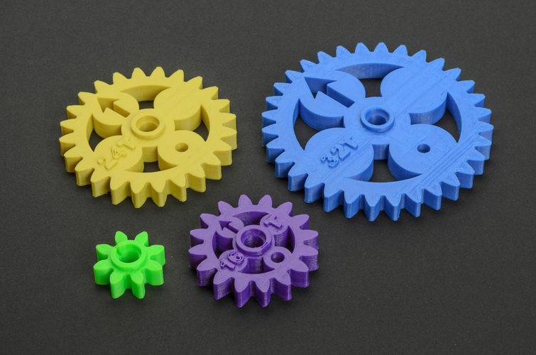 Thus, a large gear rotating at low speed can cause a smaller gear to rotate much more rapidly.
The more common scenario in gear assemblies is that the input force rotates a small gear rapidly. This is translated to a larger gear that rotates slowly but still has greater torque. This mechanism allows gear assemblies to rotate large objects or lift heavy objects with just a small application of force.
This translation of force can be estimated using the gear ratio of any particular pair of gears. This is a ratio comparing the number of teeth of two gears. For instance, a 6-tooth gear turning a 30-tooth gear yields a gear ratio of 5.
As we shall see later on, these parameters will play roles in the design of a gear for 3D printing.
Design tips for 3D printed gears
Nylon is the best material
While nothing is stopping you from 3D printing your gears in PLA or ABS, we find that Nylon produces the best results. Nylon is tough and is just flexible enough to withstand wear and tear but still provides good force transfer.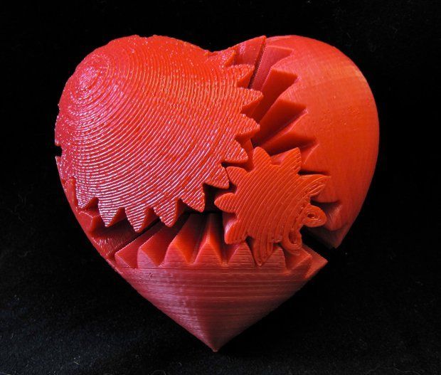 It also has a high melting point to withstand deformation from heating because of friction.
A unique trait of Nylon is that it has a fairly low coefficient of friction. This is important in plastic gears where finding a compatible lubricant can be quite difficult. If you have to use a lubricant, we suggest using a silicone-based one.
PETG may be hailed as one of the best 3D printing materials, but we do not recommend it for gears. PETG is more flexible than either ABS or PLA. This is not a characteristic that we are looking for in this scenario. Flexible materials create poor force transfer, making a gear assembly much less efficient.
Bigger is better
If you have been printing in FDM, then you probably already know the pain of 3D printing very small parts. At the onset, it’s a good idea to be realistic about what your 3D printer can achieve. Do not design gears with pitch values of less than an inch, lest you end up with hard-to-control errors.
This advice is also valid for the design of gear teeth.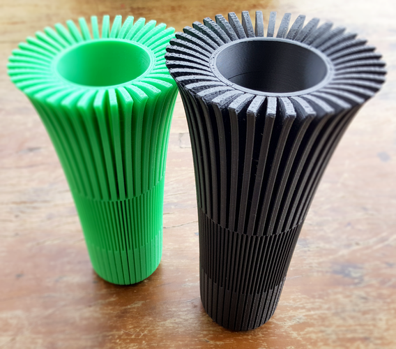 Designing your gear with more teeth provides smoother rotary motion but will also require that you 3D print smaller teeth. Not all 3D printers may be equipped for this. This free model should help you determine the minimum size of gear teeth that your printer can handle.
Setting limits on the number of gear teeth
When designing a gear, you need to determine the maximum and minimum number of teeth that your 3D printer can handle. This test model will help you check your 3D printer’s capabilities from pitch values of 12 up to 48.
Reducing the number of teeth and using bigger teeth on your gears seems like a simple solution. Bigger teeth are stronger and easier to print. However, they also produce poor torque transfer. If you need your gear assembly to be efficient, you will have to strike a good balance between pitch and gear teeth size.
Set a maximum gear ratio of 1:4
A good way to set a limit on the size of your gears is to impose a maximum gear ratio of 1 is to 4.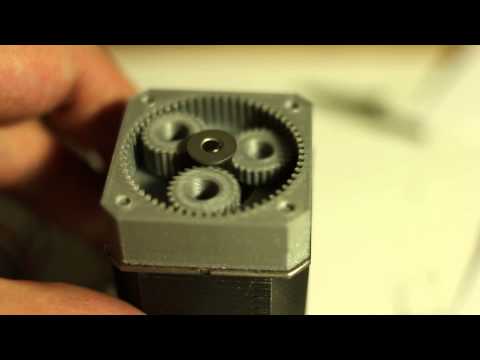 If you need your assembly to have a higher gear ratio, then we suggest breaking them apart into several smaller gears.
Triangular teeth or involute teeth?
The simplest shape for gear teeth is a triangle. As long as you use triangles with identical sizes, you should have no problem matching up pairs of gears. However, triangles have low efficiency in terms of torque transfer and tend to be quite noisy.
The most common gear shape is that of the involute circle. Involute gears are a little harder to design but are considered very efficient. This exceptional efficiency is made possible by the design of the involute gear that aims to have only a single point of contact between gears as they turn alongside each other.
Print with a solid infill
Gears can go through a lot of mechanical stress during operation. This does not bode well for 3D-printed gears, as they are not exactly well-known for their durability. The best you can do is to delay the inevitable onset of wear and tear by printing your gears as solidly as possible.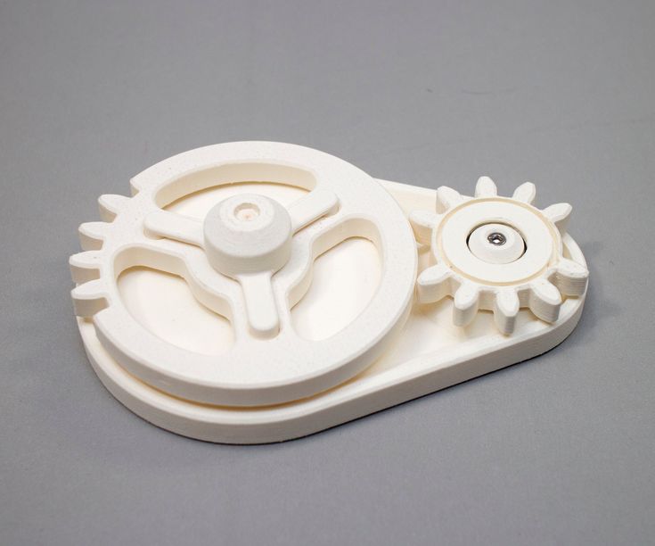
Enabling 100% infill gives your gears a bit of extra strength. Having more material in the internal space also reduces deformation, resulting in better torque transfer.
Don’t make your teeth perfectly divisible
It may seem intuitive to design gear pairs to have a number of teeth that are multiples of each other. For example, a gear with 12 teeth can pair up with another gear with 24 teeth, creating a perfect 1:2 ratio.
However, it’s considered good design to use 25 teeth instead. 25 may not be perfectly divisible by 12, but this also means that the same set of teeth will not meet up with each other for every revolution. This small design change slows down wear and tear on the gear teeth substantially.
Expect some post-processing
FDM printing is not exactly known for perfectly smooth surfaces so you will likely need to do a bit of post-processing on your 3D printed gears. Among the tasks are smoothing the gear teeth or boring center holes to make them fit your assembly.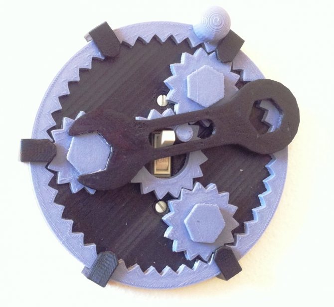 Keep in mind that you need these gears to fit perfectly snug with each other both for efficient load transfer and to avoid accelerated wear and tear.
The great thing about a 3D printed gear assembly is that you can just print replacement gears as necessary. Unlike metal parts, 3D-printed gears are cheap enough for you to not feel bad if they don’t turn out perfect.
Final thoughts
Gears can make for a very interesting project for your 3D printer. Seemingly simple, gears benefit greatly from high-precision 3D printing. If you want to sharpen your skills even further, then we recommend learning how to model and design gears from scratch.
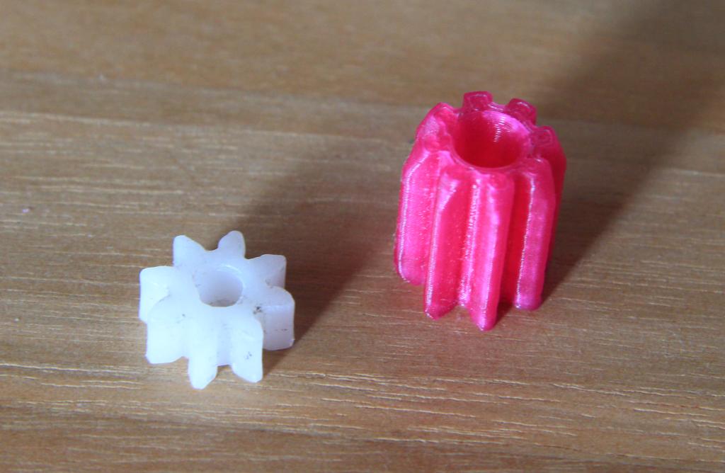
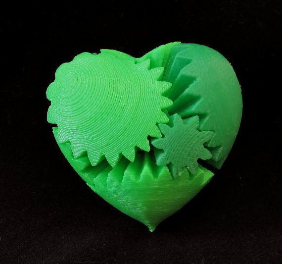
If you don’t quite know where to start, then you can try 3D printing pre-made models such as these two simple gear assemblies. Pay attention to the shape of the gear teeth and how torque transfer works. With some practice, you can eventually come up with gear assembly designs that are far more complex.
Warning; 3D printers should never be left unattended.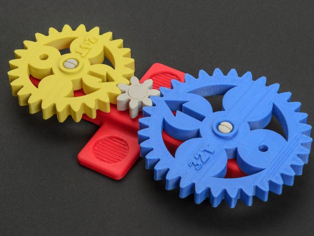 They can pose a firesafety hazard.
3D Printed Gears: Guide & Best Free Downloads
3D printing your own working mechanisms is a big part of a lot of the more complex 3D printing projects you’ll come across. Naturally, many of these homemade mechanisms need 3D printed gears to work.
Whether it’s as cool fidget toys or part of a larger project, making reliable 3D printed gears is often the linchpin of a design.
Like different ways of tying knots have their own specific purpose, there are also a lot of different gear designs suited to what you’re building. 3D printing a simple cog-style gear will work for some mechanisms, while it won’t be viable for others.
Here we’re going to look at how to 3D print gears, what kinds you can print and why, and also some useful hints and tips to keep in mind when printing. By the time you’re done here, you’ll have all the know-how to print your own gears with confidence!
Common Uses for 3D Printed Gears
In this electrical age of ours, it can be hard to think about what gears are actually used for these days.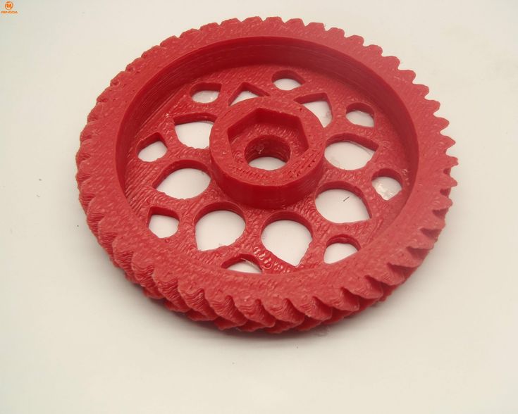 Generally speaking, when we think of gears we often think of old factories, steampunk settings, and ancient Indiana Jones-style trap mechanisms.
But gears do still play an important part in a lot of machines and tools even now. Most mechanical locks still use gears and tumblers to work, as do analog watches, pulley mechanisms, and tools like woodworking and car repair equipment.
Even fun things like homemade fidget toys use 3D printed gears as a primary staple. The mechanical concepts of speed and torque are applied to gears to make toys like Beyblades too, which you can also 3D print.
You can even use 3D printed gears to repair or enhance other machines like this geared extruder and this gluing gear print for general maintenance. Any of these designs are worth saving if you plan on working with mechanical prints for a while yet, but they also work well as one-off projects to further your 3D printing journey.
These kinds of gears are much cheaper than visiting repair stores or getting custom-made designs from professionals.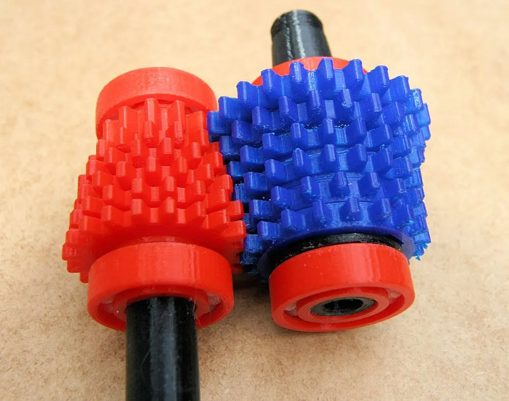 As 3D prints vs. traditional metal gears, they won’t last as long, but they’re a good option if you’re on a budget or just prefer to fix or make things yourself.
3D Printing Gears: Ideal Filaments
Different 3D printing filaments are better suited to different projects. Gears are designed to be in near-constant motion, so the filament you use should be durable to ensure longevity and reliability.
The nature of 3D printing means you’ll never really have anything as strong and tough as something factory-made and metal, but that doesn’t mean there aren’t a few things to keep in mind to ensure you get the best results.
Naturally, you’ll want to use the strongest filament available to you to 3D print your gears.
These include filaments like:
- Nylon
- Polycarbonate
- PETG
But, if none of those are available you can actually 3D print gears using PLA if that’s all you have available.
PLA may not be the first choice when it comes to strength, but with careful measurements and post-processing, you’d be surprised at how well it holds up over time.
If you’ve got the means, though, then I recommend using PLA+ if you can. PLA+ is an enhanced version of PLA in terms of durability and longevity. While more expensive, and a little trickier to find, PLA+ has been proven to make surprisingly reliable 3D printed gear mechanisms before.
Cool 3D Printed Gears
Now that you know what to do, it’s time to get printing gears! While you’ve probably got some ideas in your head already, there are still plenty of cool 3D printed gear designs and projects out there to sink your teeth into.
Here we’re going to look at a few of the best 3D printing projects that use gears practically in their designs.
Spider-Man Web Shooter
Maybe not the first thing that came to mind when thinking about 3D printed gears, but definitely the first one I wanted to talk about.
This working Spider-Man web shooter uses small 3D printed gears originally designed for watch repair to shoot webs just like everyone’s favorite web-head!
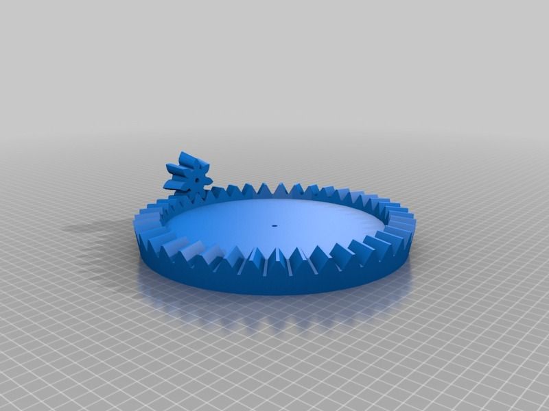
Walking Cat
Gears are an important part of many moving mechanisms, and this walking cat makes for a great project both in general and also for testing out your skills with 3D printing gears.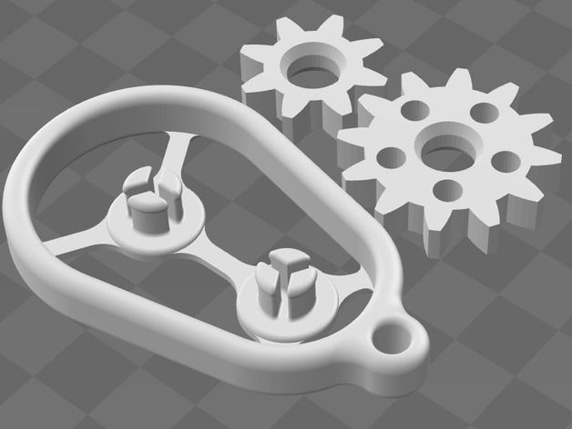
As well as being a fun toy and a great way to get used to the more complex designs 3D printing is capable of, the walking cat also uses plenty of different gears at different sizes and angles.
This makes it both a great project to sink your teeth into, as well as an excellent learning resource to see how different gears interact with each other in one mechanism.
Planetary Gearbox
Another great learning resource, as well as a fun print, is this planetary gearbox. It works like a numbered padlock, but with the inner workings visible to you.
This not only looks cool, but also makes for a good introduction to the basics of gear functionality as well as a learning tool for children or beginners in mechanical engineering.
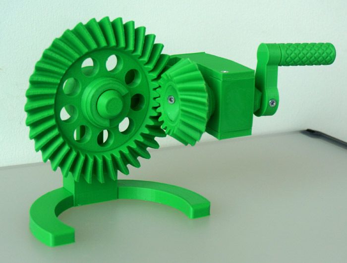
Lotus Automata
One of the coolest (and prettiest) 3D printed gear mechanisms I’ve come across is the lotus automata, a hand-cranked display piece that opens up like a real lotus flower.
While you’ll need plenty of different prints with different colors, the outcome is a great centerpiece that works well with different kinds of gears to make a fun and beautiful print that’s well worth the time and effort.
Types of Gears
There are a lot of kinds of gears, each with their own ideal purposes. Knowing which one is best for you is important for making sure your mechanism works at peak performance.
While it’s unlikely you’ll be 3D printing generators or high-end water pumps, we’re going to briefly go over what kinds of gears best fit which uses so you’ll have a better idea going forward.
Spur Gears
Spur gears are what most of us picture when we think of gears, and are the most common type of gear to 3D print.
Spur gears are simple toothed cogs that move with each other for mechanisms like pulleys and clocks, and are very useful in a variety of sizes to keep machines ticking along nicely.
Helical Gears
Helical gears are best described as curved spur gears. They are capable of withstanding more torque than their simple counterparts, and are commonly used for more load-bearing machines like generators and high-strength pumps.
Worm Gears
Worm gears employ a changing parallel design. Unlike standard gears, they can be manipulated to lock in place. This comes in handy for self-locking mechanisms like doors and hard packaging.
Worm gears effectively work against each other, and require a lot more care and maintenance as this causes a lot more wear over time.
Bevel Gears
Bevel gears are cone-shaped gears that work perpendicular to each other. The curved teeth and size difference between two touching gears mean they can handle a lot more speed than most other gear types with ease.
Bevel gears come in a lot of different types on their own, which we’re not going to go over here. The most common uses for these are in fast-moving machines and tools like vehicles and power drills.
While bevel gears can be 3D printed for fun and practical uses, their most common uses aren’t ideal for 3D printing as the heat generated by the speed is too much for most filaments to handle.
Rack and Pinion Gears
Rack and pinion gears involve one gear moving with a straight, toothed line.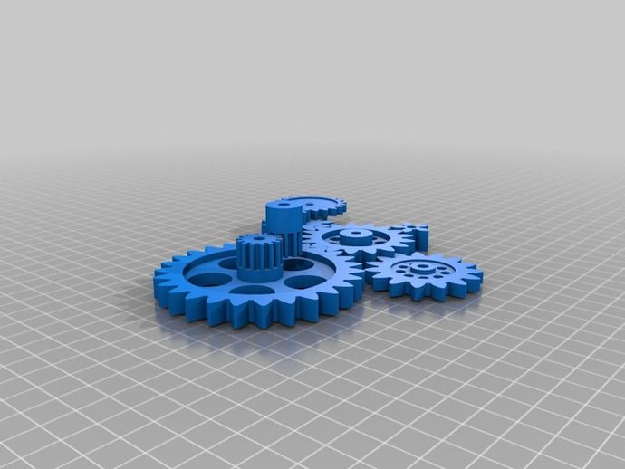 Designed to move back and forth seamlessly, they work best as guides for steering mechanisms on tools and vehicles as well as weighing scales and seesaws, which need to move in two directions with ease.
How to 3D Print Gears: Helpful Tips
As you’ve probably already guessed, 3D printing gears requires more preparation and precision than the average print. To make sure you get working gears, you’re going to need to think and plan ahead, especially if you’re printing your gears from scratch.
Here are some helpful steps and tips to make sure you get reliable results.
Plan Before You Print
Careful planning is an important step in any 3D print, but it’s even more important when you’re printing working mechanisms with moving parts.
While a millimeter or two in any given direction won’t make much of a difference in most 3D printing projects like statuettes and ornaments, with gears it can mean the difference between a functioning mechanism and a weird paperweight.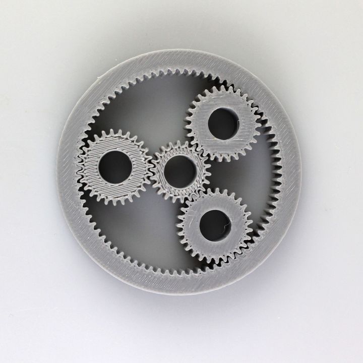
Always double-check your measurements before you get printing. You can do this with particular precision if you have particularly good STL editing software that can test your mechanisms before they’ve even been printed.
Test and Prototype
There’s nothing worse than having a great design only to find out all too late that it doesn’t quite work. The waste of both materials and time is always frustrating, which is why testing and prototyping is a great way to avoid this annoyance.
Scaling your design down before printing is one way of prototyping. The print will use less material overall and take less time to print. What you’ll have will be a miniature version of your gears so you can see for yourself if they fit well together and work as they should.
Just be sure to scale the model down exactly without tweaking anything else, otherwise you’ll get inaccurate measurements that will ultimately be useless as prototypes.
It’s not just the gears you’ll want to test, though, so be sure to also scale down the shaft on which the hears will be turning.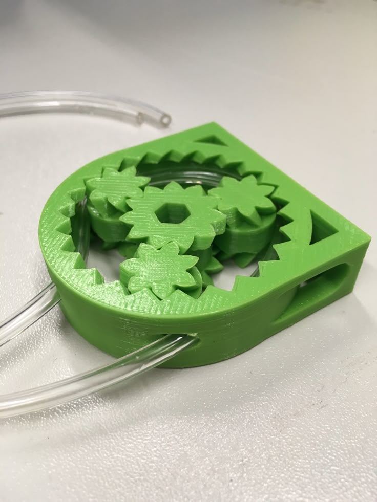 The distance between the gears is just as important as the teeth fitting together, so be sure to test every inch of your mechanisms before beginning what will hopefully be the final print.
Make Notes and Save the Files
Once you’ve got a working file, be sure to save it as is so you can return to it at any time. This will help for not only duplicate prints, but also later repairs and sharing with your friends.
As mentioned above, 3D printed gears won’t last as long as traditional metal ones, regardless of what filament you use. So keeping the file safe and easy to find will be handy when you need to replace worn parts.
Are 3D printed gears any good?
Generally speaking, 3D printed gears won’t be as durable as store-bought metal gears. This isn’t to say they’re not good, however, and with enough careful planning, 3D printed gears will be perfectly workable.
Is PLA strong enough for gears?
Despite being one of the weaker filaments, PLA can be used to make 3D printed gears.![]() While other filaments like nylon and PETG are preferable, PLA will still do the job. If you must use PLA, we recommend looking into PLA+ for any 3D printed gears and moving parts.
While other filaments like nylon and PETG are preferable, PLA will still do the job. If you must use PLA, we recommend looking into PLA+ for any 3D printed gears and moving parts.
How do you 3D print gears?
3D printing gears is as simple as any other project, the main thing to keep in mind is the precision of both the gear teeth and the shaft. With enough planning and prototyping, you can make working gears with just about any FDM filament.
How do you attach 3D printed gears to a shaft?
If you’re working with a pre-existing design, your gears and shaft should already fit together easily. However, if you’re designing your gears from scratch, you’ll need to make sure the shaft and the gear opening match in size.
Gears can be attached to shafts using screws or adhesives. For 3D printed gears, adhesives work better as they will be easier to remove for future repairs.
from which to print small gears, material of manufacture
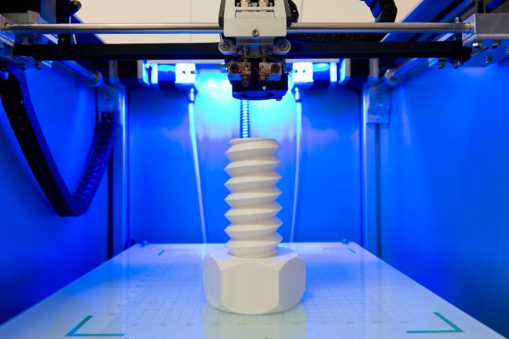
One of the advantages of 3D printers is uniformity. A novice printer can easily replace any part. Moreover, he does not have to go to the store or order an item from China. He can do all the details himself. Of particular value is the printing of gears. This is the “working” unit of the device, which is most prone to breakage and wear.
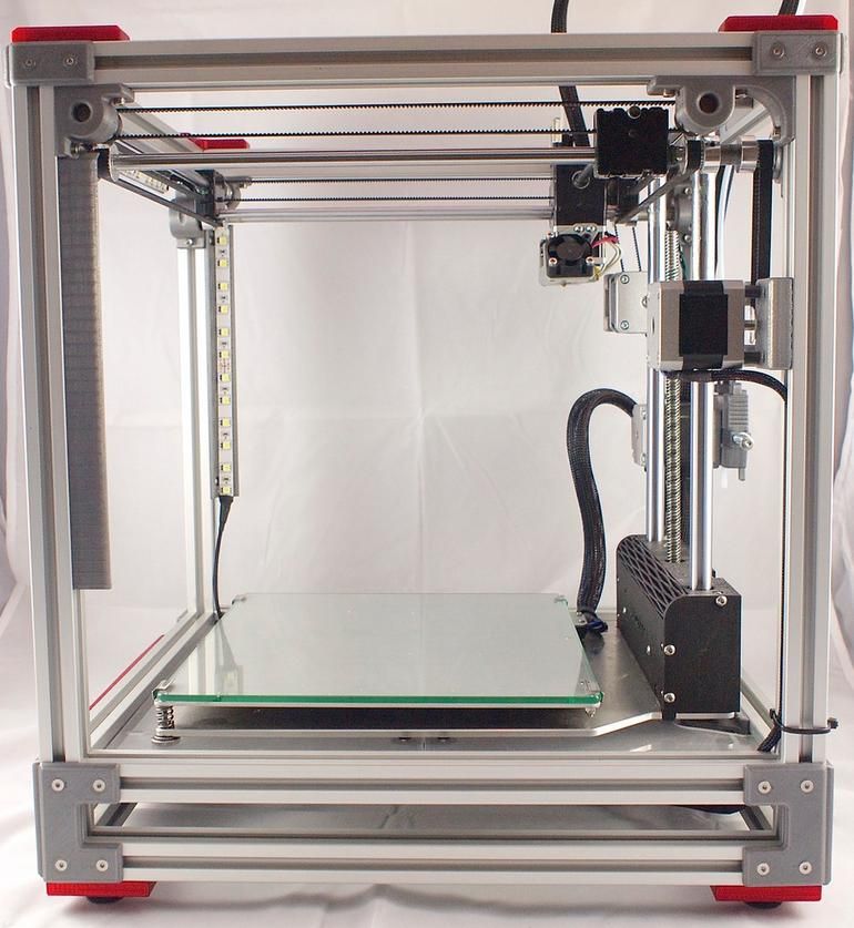
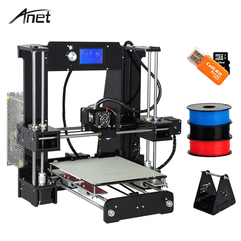
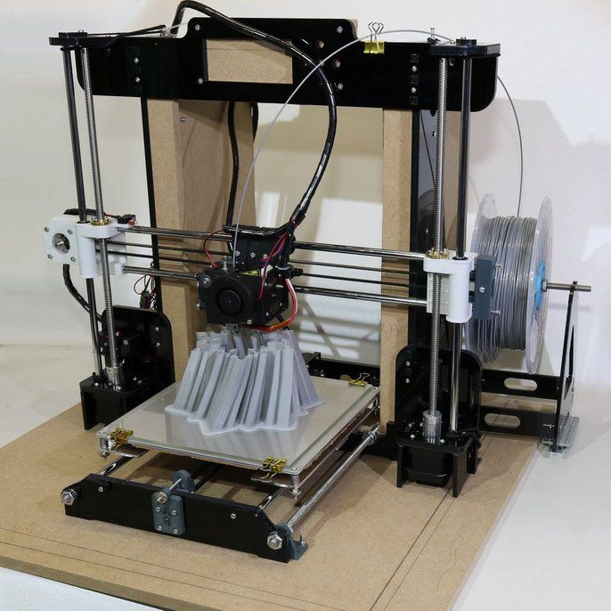
Which 3d printer is suitable for printing gears?
When we talk about printers, we mean FDM machines. These are 3D printers based on the layer-by-layer plastic deposition technology. Such devices allow you to close two tasks:
- Print broken parts. Plastic is not durable. A gear or other part may simply break or wear out.
- Printing custom or new parts. Development of spare parts from scratch. This also includes the design of gears for a homemade 3D printer.
It is difficult to name a specific printer model for making gears. It all depends on the size of the part and the corresponding working area of the machine. But one thing is for sure: the device must print with high accuracy.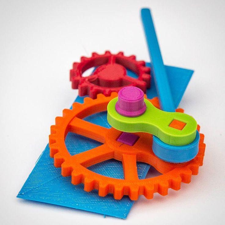 For such work, it is worth carrying out additional calibration of the desktop and extruder in order to avoid mass marriage during printing.
Important! The part design is usually downloaded as an STL file. Parts can be printed for personal use only, not for sale.
What materials are suitable for making a gear on a 3D printer?
Naturally, the main material is plastic. But it may differ, depending on the goals and the final strength of the finished product:
- Nylon (PA). Sufficiently durable material. This filament is considered one of the most reliable for the manufacture of moving parts and elements. A small minus of the material: it absorbs moisture well. You should not make gears out of nylon if the printer is in a room with high humidity.
- PETG. This type of plastic is also classified as high-strength. It is slightly inferior in characteristics to nylon. Printers appreciate it for its good sinterability of the layers, as well as for sticking to the work surface.
- PLA and ABS. These materials compete with each other. In terms of performance, they are approximately equal. Basically, the differences relate to the training of the printer himself. Some people are used to PLA and its operating temperatures of 75°C. Others have successfully used ABS by heating the material up to 105°C.
The choice of plastic depends on the skill of the printer, his financial situation, as well as on the final purpose of using the gear. If the part is lightly loaded and rarely used in work, you can choose PLA and ABS. For stronger parts, it is better to use PETG or Nylon (PA).
Interesting! PLA is known to be biodegradable. Because of this property, some printers are wary of using this type of plastic. They believe that the part can crumble over time. It's a delusion. The spare part may decompose if an appropriate environment is created for it. Nothing will happen to her in the air.
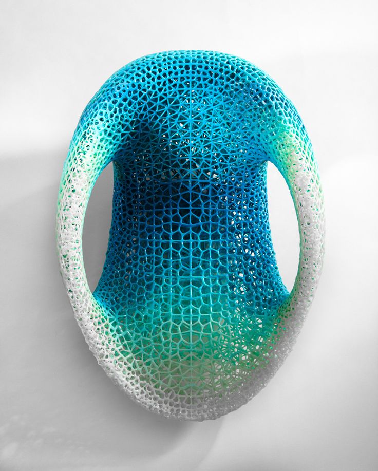
An example of finished products
How to print a gear on a 3d printer: step-by-step instructions
The entire printing process can be divided into three important stages: design (modeling), printing itself, post-processing of the finished product.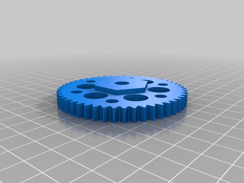 Consider the manufacture of a gear, starting with work in a slicer and ending with the final processing and lubrication of the part.
Modeling
The process of modeling is the basis. There are a few important things to keep in mind at this stage:
- If you have downloaded the industrial gear model in STL file, it is better to modify it manually. Namely, remove all cavities and holes that may be in the project. Such measures are allowed at the factory to reduce the cost of the part. At home, it is better to make a monolithic part. So stronger.
- For self-made parts, you need to calculate the optimal number of teeth, calculate the pressure angle. If your printer can print with high accuracy, without jambs, you can choose a larger gear ratio (number of links). This will affect the smoothness of the one-piece design where the gear will be installed. There are also rules for the pressure angle: for a part with a pressure angle of 20 degrees, the minimum number of teeth is at least 13 pieces; for a gear with a pressure angle of 25 degrees - the minimum number of teeth is at least 9things.

- Multi-tiered gears are best broken apart in a slicer and then glued together in post-processing. In this way, the best quality of the part can be achieved.
Be prepared for the fact that the part will have to be printed several times, along the way making adjustments to the 3D model of the product.
Slicing
Printing
The advantage of layering is that it is the cheapest way to get a part. Almost any gear can be made by yourself. But here also lie their disadvantages, which must be taken into account in the printing process itself:
- Material shrinkage. Each type of filament shrinks. You need to know it, otherwise the part will turn out to be out of size. Measure the percentage shrinkage on the test cube with a vernier caliper before printing. Add the result to the settings.
- The gear is a very precise item. Even a small deviation of 0.01 mm can affect further work. Therefore, it is important to calibrate the platen and extruder as perfectly as possible.

- Print defects. They must be removed before work begins. Print a test cube, preferably on 4 corners, to rule out any defects on the final product.
But printing is only half the battle. Without fail, the 3D maker is waiting for the post-processing procedure. And here, too, there are nuances.
3D printing defects
Interesting! Before printing, it is better to treat the desktop with ABS dissolved in acetone. Apply it in a thin layer. This will improve the adhesive properties of the surface. The first layer will not come off during the printing process.
Postprocessing
Perhaps one of the most important stages. It is impossible to rush here, as any oversight can lead to a defective product. Post-processing consists of several stages:
- Removal of supports, threads, sagging with a sharp knife or scalpel. Be careful, work without haste.
- Sanding with fine sandpaper.
 Removal and grinding of all irregularities, almost final processing.
 - Immerse the part in dichloroethane solution for 5-10 seconds. The liquid will penetrate into small cracks, glue and strengthen the part. This step is not necessary if you are working with a strong filament.
- End product lubrication. Last step. Lubrication is essential in heavily loaded systems. It prolongs the life of the part, the gears work more efficiently. For these purposes, it is better to take a thick lubricant based on: silicone, lithol or polytetrafluoroethylene. Apply the substance thickly with a dry paper towel so that no dust remains on the parts. Then forcibly turn the gear several times.
Be patient. In the post-processing process, the part may crack or even break. If this happens time after time, it may be necessary to change the filament and make adjustments to the design model.
Common causes of part failure in service: tooth wear to slip, tooth breakage due to excessive loading of the assembly, shaft fracture.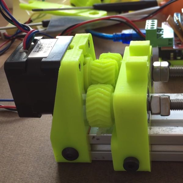 In rare cases, a hub or spoke breakage occurs.
Important! Do not use WD-40 on plastic parts. It's quite aggressive. It is designed to remove dirt from metal products, but not to lubricate plastic gears.
Post-processing part
Errors and how to avoid them
Of course, errors can occur during printing. And you need to notice them in time and be able to avoid them. We offer you to get acquainted with the list of the most common shortcomings that occur during the printing of gears:
- Reducing the diameter of the main hole of the gear. Often this is due to the fact that the user did not take into account the shrinkage of the material. Another reason is the export of the STL model with a low number of segments that form a polygonal gear hole. Always export a file with many segments. Otherwise, you will have to drill the hole manually.
- Gap between teeth. This issue can be encountered even with 100% infill enabled.
 The solution must be sought in the slicer by increasing the layer overlap parameter.
 - Low strength parts with thin walls. To make the teeth smoother, you need to set a smaller layer thickness. Straight infill printing with a minimum wall thickness of at least three perimeters.
- As mentioned above, it is better to make a solid part, without additional holes and recesses (not including the main hole in the center). You will not lose much on plastic, but the part will last longer than usual.
If a printer has never made gears on a 3D printer, then he will surely face one or more problems at once. And it is better to know about them "on the shore".
You will need a lot of patience and even more filament in the beginning.
Making gears at home is easy. The main thing is to take into account all the nuances and subtleties of the work in advance, develop an accurate model, and calculate the shrinkage of the material. You also need to be prepared for the appearance of errors or shortcomings.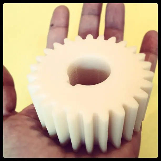 Some of them can be fixed in post-processing. Others - only by the method of complete alteration. But this is a workflow, nothing can be done about it.
- 07 March 2021
- 6585
Get a specialist consultation
90,000 printing gears on 3D printer3D-repair
Subscribe to
Subscribe
I do not want
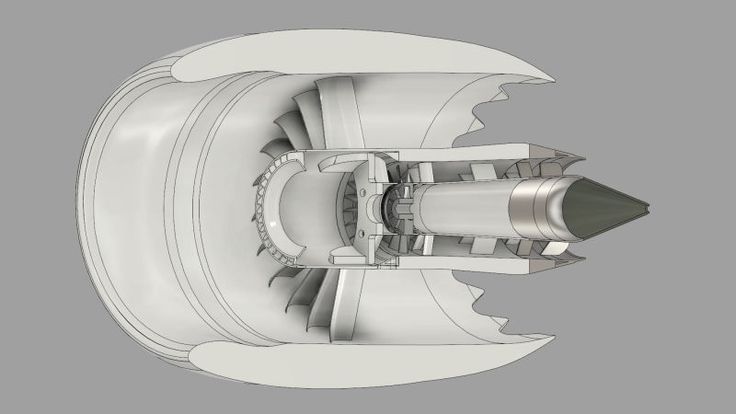
9000 31gears today are found everywhere, basically at the day and expoen , as well as in tools, industrial instruments and devices.
In the design of the gears are divided into the following categories:
- Right -toothed gears
- Blist -free gears
- Chevrony wheels
- gelets
- screw six000 - sector sector with circular teeth
- bevel gears
- toothed racks
- sprockets
- ring gears
Half of these gears are made from various types of plastic and are suitable for printing on a 3D printer.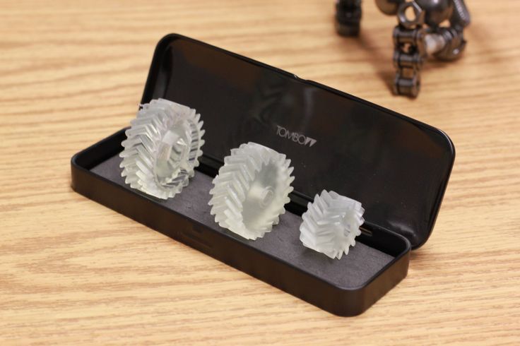
Printing a gear on a 3D printer is divided into 3 main stages:
1. Modeling.
2. Print.
3. Post-processing.
Modeling gear.
Not an easy stage and perhaps the most difficult one.
Don't be surprised if after redoing the model 5 times, you don't get the result. There are a lot of nuances here. First you need to measure the dimensions of the gear very accurately, even a small deviation of 0.1 mm can play a role. In multi-tier gears, take into account the location of the teeth of different tiers relative to each other. If possible, simplify the design and make it stronger, namely: in industrial production, multiple recesses are often made to save money. In most cases, they are not needed and only complicate printing and post-processing.
When printing multi-tiered gears, if possible, divide the gear into parts and print separately, and then join and glue,
otherwise, the plastic may delaminate at the junctions of the tiers.
Seal
The gear seal is a durability test.
Let's start with the choice of media. There are a lot of offers of dense plastic on the market. It is necessary to choose a plastic with a low abrasion coefficient. We use Relax and Nylon, in practice these materials have proved to be positive. They also have disadvantages, but more on that below.
Do not forget about the shrinkage of the material, as a rule, the percentage of shrinkage is indicated by plastic manufacturers. For greater accuracy, you can measure this value yourself. Print a cube with the exact dimensions of 20x20mm and after printing measure it with a caliper, just do not use cheap Chinese plastic electronic calipers, they give a large error, it is better to take a metal caliper with an error of 0.01 mm. Based on the dimensions of the printed product, you can calculate the percentage shrinkage of the material and add it to the product when printing.
The table needs to be exactly aligned, a small deviation can give an error in the dimensions of the gear print, critical for its operation.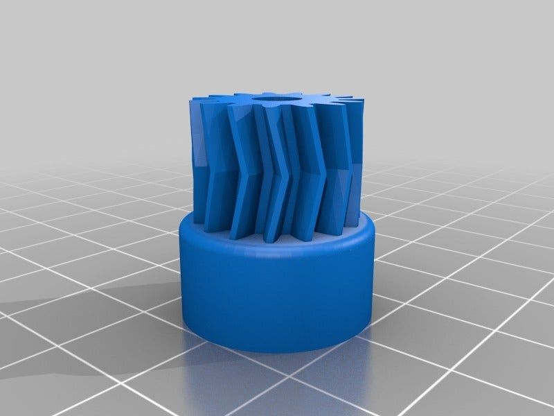
ABS dissolved in acetone is best used for material adhesion. Just make it liquid and apply a thin layer on the glass. A thick layer can warp the gear and the result will be poor. At the same time, the detachment of a part is also an unpleasant situation, especially if it was left unattended and this is the result of the work.
There may also be slight delamination which will also ruin the part.
No breaks from the table were observed when using the ABS solution.
Also very important are the print settings of the gear, namely the cooling and the distance between the supports.
This photo shows the difference between the two printed gears: on the left side the cooling is on, on the right it is off.
Each 3D printer has its own cooling settings, adjustable by experience.
The distance between the supports should be made as small as possible, this is important when printing an overhanging main gear. So that it doesn't work out like this.