3D printer set z offset
How to Calibrate the Z-Offset on the E2 3D Printer
Knowing how to operate a 3D printer includes learning how to calibrate the Z offset. The Z offset on the E2 from Raise3D has some capabilities that allow it to perform with high precision. Calibrating a Z-offset can feel overwhelming, but Raise3D improved one of the most common calibration methods to become a more straight-forward process for any user.
What is the Z – Offset and Why Does it Matter?
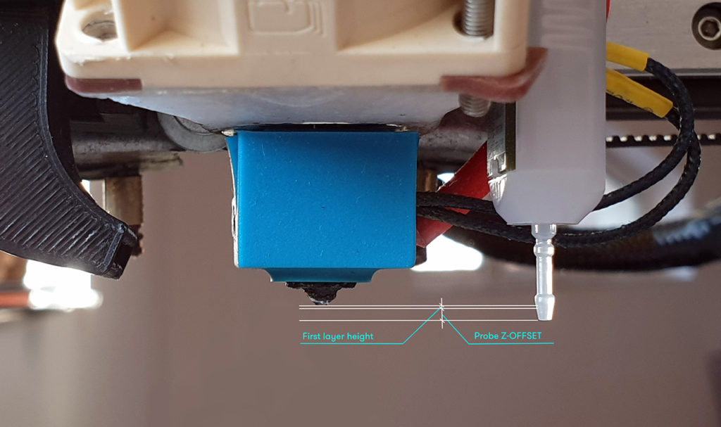
The Z-offset is the distance that the tip of the Z-probe moves before getting trigged. It is marked as “distance B” in the figure below. The Z-probe from Raise3D is designed with high precision (repeat error ≤ 0.012mm) giving it the ability to treat the distance between the tip of the nozzle and the trigger point (distance A in the figure below) as a stable value. The proper Z-offset can be determined automatically by adding the value A to the Z-offset (distance B). Keep in mind that the B distance varies slightly between probes, so achieving optimal results requires finding the correct B value for each printer.
Figure 1: Probe trigger height
What is the Best Way to Calibrate the Z-Offset?
One way for users to calibrate the Z-offset is to observe the outcome of the first printed layer, then manually set the height differences values(as shown in Figure 2). If the nozzle is too high, then the value will be too small. If the nozzle is too low, then the value should be reduced.
Overall, this method requires repeated printing and measurement, which is tedious, complicated, and inefficient.
Figure 2: Guidelines for manually adjusting the Z-offset value based on first layer results
Raise3D built on the core principle of this method and developed some preliminary improvements. The user would be presented with multiple lines at a time, with each line using a slightly increased printing height. The user would then compare all the lines and select the one with the best printing quality. This method greatly reduces measurement times.
However, our double-blind trials found two main concerns regarding this method:
1. Because the difference between the printed straight lines is slight, it is difficult for users to determine which line achieves the best result.
2. “Best” is a subjective term, and individuals have different standards for “line quality”. This resulted in deviations as great as 0.5mm between values identified as the “best” printing height.
Due to these concerns, Raise3D wanted to find a measurement method with less variability. Testing showed that when the nozzle is a certain height above the heatbed, the printed line will become wavy, but if the nozzle is below this height, the printed line will not be wavy. Selecting the first wavy line in a series is a more straight-forward task than choosing the “best” line, which resolves issue 1.
After that, double-blind trials tested whether the first wavy line is a stable indicator. The results of these trials would show whether this updated process removes the subjectivity and variability discussed in issue 2.
The double-blind trial results are as follows:
| Relative Error Compared to Standard Value | ||
| <=0.05mm | <=0.1mm | <=0.12mm |
| 95% | 99% | 100% |
Figure 3: Relative Error Compared to Standard Value.
Based on this trial result, this method resolves issue 2, and can be used to clearly and stably measure the height differences between the nozzle and the probe’s trigger point. Therefore, the E2’s offset calibration based on this method.
Some Factors Can Affect the Outcome When Using Offset Calibration 1. Different filaments will cause significant deviations in the offset calibrations measurement results
We have explored the principle of wavy line generation.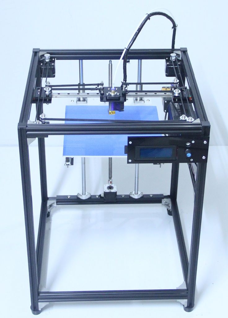 Melted filament, as anon-Newtonian fluid, will generate the Liquid Rope-Coil Effect when extruded at a certain height. When the printer head moves, the rope coil is pulled, producing an even wavy line. The main influencing factors of the Liquid Rope-Coil Effect are the melt flow index of the non-Newtonian fluid, the extrusion height, and the extrusion speed. When different filaments melt at the same temperature, the non-Newtonian fluids have large differences in melt-index. This means that filaments with different diameters under the same feed rate may have different extrusion speeds. These differences affect the height of the wavy line, which can lead to large deviations in the offset calibration measurement results.
The measurements of the offset calibrations results were compared to measurements taken with high-precision instruments to find the deviation between them. So far this comparison has only been made using Raise3D Premium PLA filaments.
For third-party filaments, users can utilize the values from the offset calibration that was performed with Raise3D Premium PLA. All filaments are different, so small adjustments may need to be made depending on the results of the first layer. Exploration on how to make the offset calibration more compatible with third-party filaments is still ongoing.
2. The center of the print surface must be flat
Since the offset calibration prints lines in the center of the print surface, applying glue or other surface treatments may affect the accuracy of the final values. It is also important that the bed be as level as possible to achieve an accurate offset value.
3. How can the printer’s Z-offset be adjusted?
There are two ways that you can adjust the Z-offset:
1. You can use the calibration menu to automatically calibrate the Z-offset. On your printer’s screen, tap “Setting>Maintenance>Offset Calibration”.
2. You can manually modify the offset in “Setting>More Settings>Hardware>Z Probe Offset”. Increasing this value will reduce the Z-offset, and decreasing this value will increase the Z-offset.
Connect with Raise3D:
Have you had a great experience with Raise3D that you would like to share? Please contact us at [email protected]. We look forward to hearing from you.
For more information about Raise3D printers and services, browse our website, or schedule a demo with one of our 3D printing experts.
What it is and how to adjust it
Adjustment of the 3D printer’s Z offset is a way to achieve successful prints in a variety of situations, such as when using filament with poor adhesion or when using a thick build surface.
This article goes over the basics of Z offset, discussing the meaning of the term, the reasons why users might need to incorporate a Z offset, and looking at how to adjust this key parameter in three different ways: using G-code, slicing software, and a 3D printer’s physical LCD display.
A Z offset is a user-defined print setting that allows the printhead to be positioned above or below the default Z home position (true zero point).
A standard Cartesian-style FDM 3D printer has a printhead that moves along three axes. Movement along the X and Y axes allows the printhead to “draw” each 2D layer, while movement along the Z axis allows the printhead to move upwards to the next layer.
Because a 3D printer has a fixed build volume, there are limits to how far the printhead can move along any of these three axes. And to prevent the printer from trying to exceed these limits, hardware manufacturers install small sensors called limit switches (or endstops) which detect when a moving part has reached its limit and cannot move any further.
The limit switch on the Z axis is important because it effectively prevents the printhead from burrowing into the build surface, which could potentially cause damage to the print bed and the hotend. The limit switch recognizes when the printhead is at its lowest possible point, and prevents it from descending further. The Z probe on a printer with automatic bed leveling performs the same function.
The “home position” of the printhead more-or-less corresponds to the position where these limit switches kick in. So when a printer is “homed,” the printhead sits in a corner of the print bed, just fractionally above the surface. But sometimes a user might want the printhead’s default starting position to be slightly higher or lower on the Z axis. This can be achieved by introducing a Z offset, and there are several reasons why a user might do this.
It is important to understand that adjustment of the Z offset is not an essential form of calibration like bed leveling. Bed leveling, which should be performed when a 3D printer is set up or when a new component has been installed, ensures the nozzle is the correct distance from the print bed at every point across the build surface. It is a necessary procedure for preventing print failure.
By contrast, adjusting the Z offset is a secondary step that users may wish to perform in order to accommodate changes to material type or build surface, or simply to achieve a better first layer. Reasons for adjusting the Z offset include:
First layer: Setting a Z offset can help achieve a good first layer that is neither too far from the build plate (which can lead to adhesion issues[1]) nor too close (which can lead to extrusion issues).
Compensating for change in build surface: If changes are made to the build surface — adding a PEI sheet on top of the bed, for example — then the printhead may need to be repositioned so it does not sit too close to the new surface.
Catering to a different material: Some filaments (PLA, for instance) work best when slightly squashed down onto the build surface in order to improve adhesion; others (like PETG) respond better when deposited from a greater height.
Printing onto a substrate: It is possible to print directly onto another object rather than onto the print bed.
 An easy way to do this is to adjust the Z offset to compensate for the thickness of the substrate.
Printing onto a thick glass build surface may require a positive Z offset
Before making adjustments, users should level their print bed, either using their printer’s auto bed leveling function or by manual adjustment of bed leveling knobs.
Auto bed leveling (ABL), a feature that is becoming more common on FDM printers, involves the use of a component called a Z probe. This probe measures the gap between the print bed at nozzle tip at different points on the bed. If the distance is equal at all points, the bed is level; if the gaps differ between points, it is not. Confusingly, ABL doesn’t actually involve a physical leveling of the bed. Rather, it instructs the printhead to compensate for any unevenness by adjusting its height at different points.
Manual bed leveling, on the other hand, does involve physically leveling (or tramming) the bed. The most common method is to use a piece of paper sandwiched between the nozzle and the build surface; when pulled, the paper should offer slight resistance. If there is no friction, the nozzle is too far from the bed, but if the paper offers too much resistance or gets stuck, it is too close. This exercise should be repeated at different points across the bed, with the bed leveling knobs used to make incremental adjustments.
One way to adjust Z offset when 3D printing is to use G-code. However, beginners may prefer to use the more intuitive Z offset settings in their slicer or on their printer’s LCD display.
The relevant G-code commands for adjusting Z offset are G0 (move) and G92 (set position). To add a 0.1 mm Z offset (i.e. to increase the space between bed and nozzle tip by 0.1 mm), input the following commands:
G0 Z0 (This instructs the printhead to move to the zero point on the Z axis.)
G92 Z-0.
 1 (This instructs the printer to interpret its current position as though it is 0.1 mm lower. So, logically, the next time G0 Z0 is input, the printhead will position itself 0.1 mm higher than it did the first time.)
An alternative way of achieving the same effect would be to input the following commands:
G0 Z0.1 (This instructs the printhead to move 0.1 mm above the zero point.)
G92 Z0 (This instructs the printer to treat its current position — 0.1 mm higher than the original zero point — as the new zero point.)
Note that to add a negative offset — i.e. to decrease the space between nozzle and bed — then any positive values in the above examples should become negative ones, and any negative values should become positive ones. For example, inputting the commands G0 Z0 and G92 Z0.1 will position the nozzle tip 0.1 mm closer to the bed.[2]
A slightly easier way to adjust the Z offset is to change the settings in your slicing software. The outcome is the same, as the slicer is effectively just changing the G-code, but the interface of the slicer may be more user-friendly, especially for beginners.
Setting a negative value will position the printhead closer to the build surface than true zero, while setting a positive value will move it further away from the build surface.
Simplify3D
To adjust Z offset in Simplify3D, find the “G-Code” tab under “Edit Process Settings.” The “Z-Axis Offset” setting can be found in the “Global G-Code Offsets” section, along with offsets for the other two axes. The Z offset is defined in millimeters.
Cura
To adjust Z offset in Ultimaker Cura, a Z offset plugin like this one is required. Once the plugin is installed, search “Z Offset” in the settings search bar (under the “Profile” drop-down box) to bring up the parameters. The Z offset value is defined in millimeters.
Slic3r
To adjust Z offset in Slic3r, navigate to “Printer Settings” (not “Print Settings”). Z offset, defined in millimeters, can be found in the “Size and coordinates” section at the top of the page.
All 3D printers running Marlin firmware (including the Creality Ender 3) allow for adjustment of Z offset using the printer’s LCD display.
On the display, navigate to the “Control” section. Within that section, find the “Motion” settings. Z Offset is the first parameter in this group of settings.
Finding the ideal Z height for a print can take time, but adjusting Z offset is a relatively simple procedure that users should exploit in order to accommodate new build surfaces and new materials, or when troubleshooting issues with the first layer. The easiest way to add a Z offset is to adjust settings within the slicer, but more experienced users may prefer to use G-code commands.
[1] Singh A, Yadav PK, Singh K, Bhaskar J, Kumar A. Design of 3D Printed Fabric for Fashion and Functional Applications. InAdvances in Manufacturing and Industrial Engineering 2021 (pp. 729-735). Springer, Singapore.
[2] RepRap contributors. G-code [Internet]. RepRap. 2022 [cited
2022 May 27]. Available from: https://reprap.org/mediawiki/index.php?title=G-code&oldid=189591
Build Tronxy X3 3D printer - setup
previous page >>>
DIY kit
First of all, when I saw this kit on sale, and then, in the process assembly and debugging, I rushed to look for at least some mention of it in Networks. I wanted to use someone else's experience in assembling, launching and configuring, reduce the time until a normally working device is received. It didn’t turn out very well - as usual, there are recommendations, but they look for the most part doubtful, strange, and in places obviously wrong. I had to figure it out myself, I post the results here, in sequence that he went through.
I will note as an important moment for the "young builder" - set works "out of the box" , all wires are connected according to the instructions manufacturer, no changes to the control board, firmware "marlin", improvements and improvements to the power supply and the mechanical part printer was not carried out. Everything that has been done is described below.
1. Auto level with capacitive sensor
This is the first thing to set up after assembling the printer.
The design has two Z-axis motors that operate simultaneously, raising and lowering the print head (hot end), along with all the mechanics of the X axis (which moves left and right). it good - the frame does not warp in the guides, at the same time they are not mechanically connected in any way, and the switched off motors can be turned regardless. Therefore, the first thing to do is to set a profile the X axis parallel to the base of the frame by twisting one of the Z axis motors. The easiest way to do this is with a caliper. You can also use any suitable object, applying it to uprights and seating both sides of the X-axis profile at its height.
We unscrew the adjusting nuts of the printer table so that the thread did not protrude - flush with the surface of the nuts. Next - turn on printer and do "auto home", which is located in the "prepare" section. The printer will move, lower the head in the middle of the table and on the sensor, which is fixed on the head, the red light will turn on. At least least - all the wires are connected correctly, and everything works.
Now you need to set the table to the horizon. Turn off the printer, now You can move the X and Y axes by hand. We expose the print head above each adjusting screw of the table and achieve an equal distance between printer head and table top at all four corners. In that In fact, a caliper is also very convenient.
Do "auto home" again. After that, you need to measure the distance from the tip of the printhead nozzle to the tabletop. It doesn't look easy but first you need accuracy within 2-3 tens, so I, for example, I measured the dimension of the entire "top - nozzle" assembly, and subtracted this value from the measurement "top-table surface" (on the top photo)
The resulting difference is the distance from the tip of the nozzle to table surface. It must be entered into the EEPROM of the printer - it permanent memory where constants are stored. "Control" section, "Motion", "Z offset" - set the value in millimeters and tenths. Then we return to "Control" and execute "Store memory". If not confidence in the quality of the measurement, it is better to put a smaller value, the printer at the beginning of printing will not rest against the table with the head when "span", and it will be possible to clarify the value later.
After that you can do "Prepare" - "Auto leveling". Printer determines the level of the table at nine points along the perimeter and averages (as far as I understood :)) Z-axis shift value depending on "curvature" of our table level setting.
Hardware ready for testing.
We install the software program repeater host, we connect the printer, we load something small, for example such a detail, and send it to seal. As a result, a small stub should be printed, but we first of all, the outline is interesting, which is printed in one line around the detail. Its default height in the program settings is 0.35 mm for the first layer. Farther - simply. If the thread turned out to be thicker - add the difference value to value "Z offset", thinner - remove.
This completes the table calibration and more special does not require attention.
bar feed calibration and printer upgrade>>>
Simplify3D manual. How to use Simplify3D
04/14/2020 in Expert Blog, Observations, Science, Equipment, Education, Articles, Technologies
Introduction.
I'm sitting at five in the morning, working, and here you are, a letter has arrived. A person cannot prepare a print job for a 3D printer. Asks for help. Have you seen the time? The landfill is not working, Kislayser too, but the person is suffering, I think let me help. The result of my help was gratitude and a well-printed part. And by the way, I didn’t lift a finger, I just uploaded the model in Simplify and prepared the model for printing through the profile I had previously configured. But when you sit at 5 in the morning and work, even such a trifle distracts.
I decided to write my manual because I couldn't find any decent information on the Internet, especially in Russian. There is one video, but a colleague explains it somehow long and drawn out (link to video below). Probably I'm used to perceive information in the form of text. It seems to be getting old.
I was also repeatedly asked to record a separate video explaining all the features of the program, but I decided to write a text article. Why? Because it is more convenient to use the article if you forgot something. I'm using the macOS version as an example.
Introductory part I want to start with the reason why I use Simplify3D.
- The program is very easy to use.

- No equal in code preparation speed.
- Works well with large models (other slicers just freeze for ever). However, the power of your computer should be sufficient. Although this is not news. We must understand that we are working with 3D models. For such work, the default computer should be as powerful as possible.
- Ability to work with processes. At the time of writing, analogues do not have such an opportunity. Processes allow you to set different print options for different layers.
Program start.
And so let's start. And we will start by learning to distinguish between what is a profile and what is a process in simple.
A profile is a basic file that contains the main printer settings: workspace size, origin, number of extruders, temperature conditions for different materials, start-code, end-code, etc. All this can be configured and changed when g-code is prepared, while the basic settings are pulled from the profile.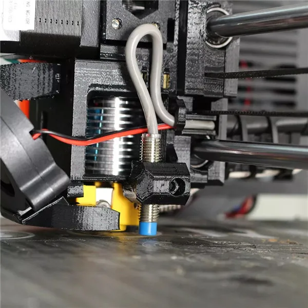
However, it is not the profile that is responsible for preparing the G-Code, but the process assigned to this profile or, if necessary, several processes. In the process, all other print parameters are set: layer height, number of supports, print speed, etc. It should be noted that the profile is one, and there can be an unlimited number of processes. For example, if there is a need to print half of the part with a layer height of 0.3 mm, and half 0.2 mm. Or part of the part should have 20% infill and part 50%.
For almost any 3D printer, a profile and processes can be created manually, and this will be discussed in this article. If you are too lazy to read or circumstances do not allow you to devote time to studying this article, you can send a request for prepared profiles to [email protected]. Everyone else, read on.
I won't focus on installing the program, because if you don't know how to install the program on your computer, then you are not destined to learn Simplify3D.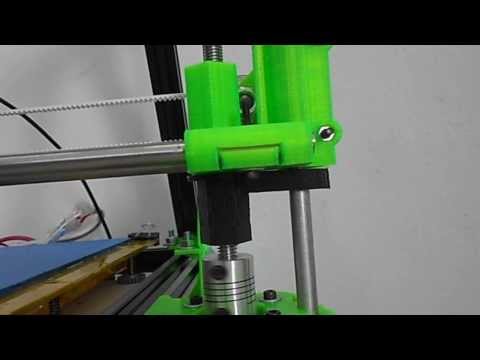
Open the program and see the main screen.
In the picture I have shown what each button means. To simplify the learning process, I advise everyone to click on each button and try how it works by first downloading your 3D model. To load a 3D model, you need to click on “import” in the “3D list” section or stupidly drag the model into the program window.
What should be done right away?
Switched to work in Simplify3D, I also worked in other slicers. Almost everywhere the speed is shown in millimeters per second. For some reason, in Simplify3D this parameter is measured in other units. To fix this ailment, you need to go to the settings.
Let's go over the rest of the buttons:
Unit system - Select the measurement system. Actually, we choose in which measurement system it is more convenient to work in Inches - inches or Millimeters - millimeters.
Swap mouse scholl wheel zoom direction
Midle mouse button resets view - Pressing the mouse wheel (or middle button) resets the virtual field camera to its standard position.
Save and restore application state - Saving the program state when exiting it and restoring it when entering;
Check for updates at startup - Automatic check for updates;
Mouse/Keyboard Shortcuts - Hotkeys.
Let's go through the settings tabs:
Machine type - Printer type. For conventional Cartesian printers, we leave Certesianrobot by default, respectively, for delta printers, select Delta robot.
Build Volume - Dimensions of the printable area.
Origin offset - Zero offset. Simplify 3D allows you to adjust the work of end caps. At first glance, a useless thing, but sometimes it can save time on setting their position.
Homing direction - Home position. In other words, the origin of the axes.
Flip build table axis - Invert axis directions. If the polarity of the stepper motor windings is reversed when assembling the printer, in order not to re-plug the connector on the printer control board, use this function by checking the box.
The choice between Y—axis is vertical and Z—axis is vertical consists in choosing the left or right triad of coordinate axes. For which printers this was done, I can’t even guess, we leave Z-axis isvertical by default.
Automatically scale to correct unit system without prompting - Automatically scale to the selected unit system.
Center and arrange models after importing
Calculte normal independent from imported file Calculate normal independence from imported file.
Only show front side of triangles (culling) — Show only the front side of the triangles from which the model is drawn.
G-Code Preview Quality - Select the quality of the model preview after slicing, respectively High - high quality, Low - low quality.
Automatically load preview after slicing - Automatic display of the model after slicing for preview;
Include build table in virtual environment - Enable table display in virtual environment.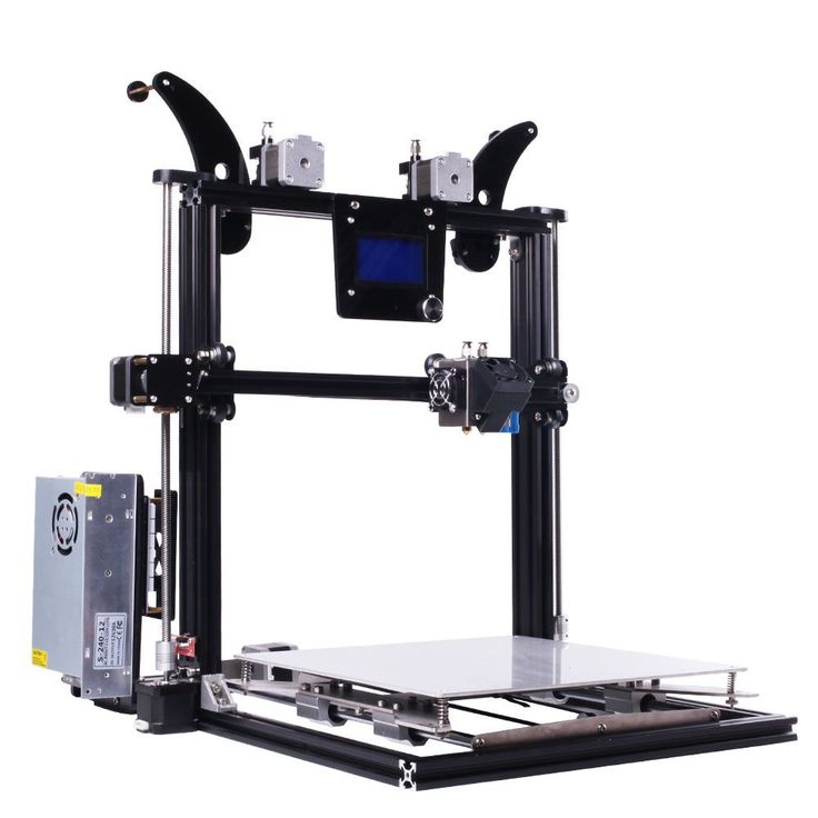
Show extruder retraction moves — Enable display of extruder retraction moves in preview mode.
Show machine movements in preview - Enable display of extruder movement during printing.
Show toolhead during preview - Enables the display of the toolhead during print.
Vertex Buffer Size (advanced) — Size of the model point buffer.
Color Setting - Color settings.
Default model color - Model color.
Selected model color - Selected model color.
Support material color — Support color.
Preparation of G-Code (control program for 3D printer)
Creation and setup of process
To prepare the code for the 3D printer, you first need to create a process. To do this, click add in the “List of profiles” block.
Before us opens a set of profile and process settings. If you have not opened the full set of settings, but only a part, then click on the button Show Adanced .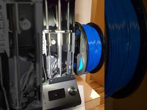 No, of course you can use a 3D printer in user mode, not professional mode, but then why do you need Simplify3D at all? After all, it's not a microwave. Different parameters and settings can give different results and properties of the part.
The point here is to set the settings for the nozzle diameter - Nozzle Diameter , extrusion multiplier - Extrusion Multiplier , and the actual extruded width of the molten filament - Extrusion Width , for each of them. To distinguish extruders from each other, each needs to put down its index - Extruder Toolhead Index . How to correctly set the value of the actual extrusion width ( Extrusion Width ) read in a separate article.
Ooze control - Control of plastic flow from the nozzle;
Retraction Plastic retraction. It must be turned on and configured, otherwise the models will be with snot, the thread will seize in the wrong places where the slicer counts, etc.;
Retraction Distance - Retraction distance.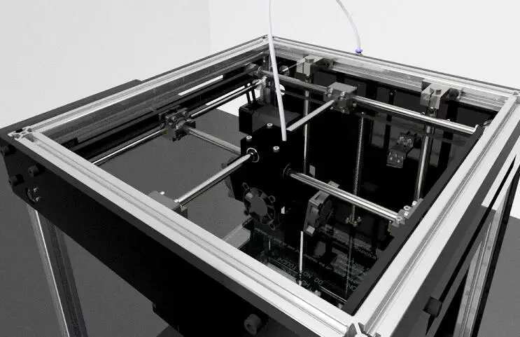 The parameter depends on many factors, from the manufacturer of the filament to the device of the extruder, therefore it is configured individually;
Extra Restart Distance
Retraction Vertical Lift Nozzle lift to move it from one print location to another. Helps prevent printed plastic from melting;
Retraction Speed - Retraction Speed;
Coast at End - Turn on retraction after printing is finished;
Coasting Distance - Length of retraction after printing is completed;
Wipe Nozzle - Enables wiping the nozzle from leaked plastic when it is heated against the platform, during the start of printing;
Wipe Distance - The length of this wipe.
Layer tab
Layer Setting - Basic layer settings;
Primary Extruder - Extruder number/name. If your printer has several extruders, then it is possible to set their own layer parameters for each. For example, if you are printing a model that is complex in its shape and there is a need for additional supports, the ideal option would be to print them with PVA (wiki) plastic (it dissolves in water type) with a nozzle with a larger diameter and with a higher layer height to save time;
Primary Layer Height – Layer height. It is easy to guess that the lower the layer height, the higher the quality of the side surfaces, however, the duration of creating a 3D model increases in direct proportion, so you need to determine a certain golden mean for each part, taking into account its further purpose;
Top Solid Layers - Number of top layers of the part;
Bottom Solid Layer - Number of bottom layers of the part;
Outline/Perimeter Shells - The number of "shells" of the side parts (walls) of the part;
Outline Direction - Print direction of the layer. Two options: Inside Out - first the inner part, then the outer, Outside-In - vice versa, first the outer part, then the inner. I tried to print in different directions, there is no visual difference, theoretically the first option is better, since it excludes the deformation of the outer shell due to "holding";
Print islands sequentially without optimization - Sequential printing of "islands" without optimization;
Single outline corkscrew printing mode (vase mode) - Enabling this mode makes an “empty barrel” from the loaded model with a wall thickness of one nozzle pass, and the printing itself takes place in a spiral with a continuous rise along the vertical Z axis. What is needed Vase Mode you can read here.
First Layer Setting - First layer settings. Parameters are set relative to the nominal layer height Primary Layer Height ;
First Layer Height - The height of the first layer;
First Layer Width - Proportional Width. The printed figures have a small feature in the form of protruding first layers. This is due to the fact that the lower layers are more smeared to ensure good adhesion of the model to the platform. By decreasing this parameter, you can get rid of this feature;
First Layer Speed First layer print speed. This parameter also greatly affects the quality of adhesion of the first layer to the platform. It's simple, the lower the speed, the better the plastic will lie.
Start Points - Start point for printing
Use random start points for all perimeters
Optimize start points for fastest printing speed
Choose start point closest to specific location
Additions tab
Skirt Settings - Outline setting. This line is needed in order to squeeze out a little plastic before direct printing;
Include Skirt/Brim – Include a stroke line;
Skirt Layers - Number of layers, i.e. height;
Skirt Offset - The distance that the skirt will protrude from the base of the model;
Skirt Outlines - Skirt width in number of lines.
Raft Setting - Raft settings;
Include Raft - Include raft;
Raft Layers – Raft height, set by the number of layers;
Raft Offset - The distance that the raft will protrude from the base of the model;
Raft Infill - Infill density of raft layers;
Disable raft base layers - Disables the base raft layer. This is a literal translation, yet I do not know what is meant here.
Use prime pillar - Settings block for building a garbage pillar. It is necessary so that before printing with another extruder, he cleans the nozzle.
Prime Pillar Extruder – Indicates which extruder is involved in cleaning.
Pillar width
Pillar location
Speed mulplier - Garbage column printing speed.
Use Ooze Shield is an outer shell around a part for printing with plastics with shrink properties.
Ooze Shield Extruder - which extruder to use to build the shell.
Offset from part – distance to the model from the shell.
Ooze Shield outline - number of shell perimeters.
Sidewall shape - shell type.
Sidewall Angle Change is the angle at which your printer prints without backing material.
Speed mulplier – shell printing speed from that specified for printing.
Infill tab
Infill settings are set on this tab. Provided that the model is not made integral, and this happens almost always, the internal structure of the model determines its mechanical parameters. With standard settings, the models are usually quite strong, if you need more transverse rigidity, you need to pay attention to these settings.
General - Basic filling settings;
Infill Extruder - Selection of the extruder that will print the internal structure of the part. A very useful feature for those who have a printer with two or more extruders. An example of when this function can be useful is straightforward. For example, you need to print a model from expensive Wood plastic, to save it, the inner, invisible part can be printed with ordinary ABS, this will significantly reduce the final cost of the part and make it stronger;
External Fill Pattern - Selection of the shape of internal lines: Rectilinear - rectilinear or Concentric - radii and circles with one center;
Interior Fill Percentage
Outline Overlap The padding will infect the width of the perimeter by the value that is set to this item as a percentage;
Infill Extrusion Width - material supply during filling;
Minimum Infill Length – Minimum length of the infill mesh section;
Combyne Infill Every - Infill grid spread, after a certain number of layers;
Include solid diaphragm every - Enable printing of monolithic layers, after a certain number of layers. This option can increase the rigidity of 3D models;
internal infill angle offset - internal infill angle
External infill angle offset – external infill angle
“Support” tab You can read more about what support structures are in
separate article .Generate Support Material – Enable support generation;
Support Extruder - Selecting an extruder for printing supports. I described the chip of this function in PrimaryExtruder, if you forgot, then read again above;
Support Infill Percentage Do not print them monolithic;
Extra Inflation Distance - The distance around the supports will be free;
Support Base Layer - In order for the support not to come off the groan, you must set the number of layers in the base;
Combine Support Layers every - Group support lines together every;
Dense Support Layers - Select the number of layers filled;
Dense Infill Percentage - Density of filled layers;
Support Type - two options to choose from, either everywhere or just from the table. If you select the second option, the support will not be built from the top floor of the model. Sometimes it is useful when you do not want to spoil the model with crafts. Check if the model is correct.
Support Pillar Resolution - The size of the column that performs the support function;
Max Overhang Angle - The maximum overhang angle for which support will be generated.
Horizontal Offset From Part - Distance through which horizontal branching of supports is possible;
Upper Vertical Separation Layers - Number of layers through which upward vertical branching is possible;
Lower Vertical Separation Layers - The number of layers through which vertical branching from below is possible;
FFF Profile and Factory File setup.
At this point, the main thing is to understand the differences between FFF profile and Factory File. Both are a set of settings. In the case of FFF profile, the file contains a set of 3D printing parameters (nozzle diameter, materials, qualities, temperatures). The Factory File contains the parameters of the 3D printer itself (field size, scripts, coordinates). If you want to transfer the workspace from one printer to another, then first transfer the Factory File, and then you can import and export the 3D printing settings using a profile. To do this, use the buttons on the top line of the program:
See separate post for how to properly set up a profile in Simplify3D.
Temperature tab.
In this tab, you need to configure the temperature modes of the extruders and the heating platform.
Temperature Controller List - List of added configurations for extruders or platform;
Temperature Identifier - Selecting the temperature sensor identifier;
Temperature Controller Type - Type of temperature controller: Extruder - extruder or Heated buildplatform - heating platform.
Relay Temperature Between Each – Selection of how often the temperature will be requested for control: Layer – every layer or Loop – every cycle;
Wait for temperature controller to stabilize before beginning
Per-Layer Temperature Setpoints - Here you can select the temperature for each layer. For example, when printing with ABS plastic, we set 240 °C for the first layer, and 220 °C for the remaining layers. In this way, the plastic will stick very well and the layers will lie more evenly.
Layer Number – Layer number;
Temperature - The temperature that the printer will maintain on a given layer.
Cooling tab
This tab sets the operation parameters of the forced air fan.
Per-Layer Fan Controls - As with temperature, you can set specific fan speeds here.
Layer Number - Layer number;
Fan Speed - Fan speed;
Blip fan to full power when increasing from idle when printing is finished.
Fan Overrides - Fan speed reset;
Increase fan speed for layers below - Increasing the fan speed for layers whose print time is less than the set time value;
Maximum cooling fan speed – Maximum fan speed;
Bridging fan speed override – Fan speed when printing bridges.
G-code tab
G-Code Options -G-code parameters
5D FIRMWARE E-Dimension) -included G-COMS These are 3 main axes and 2 extruders.
Relative extrusion distances extrusion distances (i.e. G92 E0)
Include M101/M102/M103 commands - Include commands M101/M102/M103;
Firmware supports “sticky” parameters – Enable non-G and M-code parameters.
Apply toolhead offset to G-code coordinates - Allow tools to move even in areas where there is an offset.
Offset - Offset of the initial values by the set value.
In the right part of the window of this tab, the machine settings (duplicated in the settings)
Scripts tab
This tab specifies the commands that the printer must execute:
Starting Script - At the beginning of printing;
Layer Change Script - On each layer;
Rectaction Script – Retract;
Tool Change Script - Tools;
Ending Script - At the end of printing. It can be useful to write commands here, for example, I wrote that the head should park in the zero position and the platform would extend as far as possible, so it is very convenient to shoot the finished model.
What the commands mean can be seen here, and I will consider the most popular ones.
The teams themselves are divided into groups:
G - Preparatory (main) teams;
M - Auxiliary (technological) commands.
These commands have parameters.
x - coordinate of the trajectory on the axis X [ G0 X100 Y0 Z0 ]
Y - coordinate of the trajectory on the Y axis [ G0 X0 Y100 Z0 ]
9000 Z - coordinates Z axis [ G0 X0 Y0 Z100 ]E - coordinate of the plastic extraction point [ G1 E100 F100 ]
p - command parameter [ m300 S5000 P280 ]
S - command parameter [ G04 S15 9009]
F - command parameter, feed (speed) [ G1 Y10 X10 F1000 ]
G - commands
G0 - idle, without work of the tool [ G 0 X 10 ]
G1 - coordinated traffic on the axes of X Y Z E [ G 1 x 10 ]
G4 - pause in seconds [ G4 S15 ]
G28 - PARKEMENTENT FELD [ G28 YU0 X0 X0 X0 9004 ]
G90 - Use absolute coordinates [ G90 ]
G91 - Use relative coordinates [ G91 ]
G92 Set current position3 G92 ]
Explanation:
Relative coordinates are coordinates relative to the current position of the head.
For example, if the head is in the X10 Y10 position, then when the command G91
G1 X10 F1000 is given, the head will move 10 mm along the X axis at a speed of 1000.
This command can be done many times, before reaching the "software" limitation in the firmware.
Absolute coordinates are coordinates that are strictly tied to the workspace.
When executing the command G90 G1 X10 F1000 - the head will move to the X10 coordinate at a speed of 1000.
The command will be executed only once times.
Regular commands
M0 - Pause and wait for a button to be pressed on LCD displays (works if the ULTRA_LCD parameter is set in the firmware) [ G0 X10 Y10 Z10 M0 ]
M17 - Apply current to the motors (motors do not rotate by hand)
M18 - Remove current from the motors (motors can be rotated by hands, similar to M84)
M42 - Contact management ]
M80 - Power on, ATX only - power supply
M81 - Power off, ATX only - power supply
M84 - Shut down all axes (motors after idle) [ M84 S10 ]
m112 - Emergency Stop
M114 - Get current coordinates
m115 - get a version of the firmware
m117 - write a message on the screen [ m17 Her M119 - Get limiter status
M300 - Play sound0002 M20 - Read SD card (Read the list of files)
m21 - initialize SD card
m22 - use SD card
M23 - select a file with SD card [ m23 Filiname. gCode ]
M24 – Start/resume printing from SD card
M25 – Pause printing from SD card
M26 – Set SD card position in bytes [9 M 25 S 0234]0003
M27 – Check print status from SD card
M28 – Write file to SD card [ M 28 filename . gcode ]
M29 - Finish writing file to SD card
M30 - Delete file from SD card [ M 30 filename . gcode ]
M31 - Get the value of how much time has passed since the last M109
M32 - Select a file from the SD card and start printing [ M 32 / path / filename # ]
M928 – Logging to SD card [ M 928 filename . Gcode ]
Extruder
m82 - install an extruder in an absolute coordinate system
m83 - install an extruder in a relative coordinate system
m104 - expectation of heating extruders to a certain temperature [9009 m103
M105 - Get current extruder temperature [ m105 S2 ]
m106 - turning on the fan of the part of the part [ m106 S127 ] - power 50%
m107 - turn off the fan of the unit of the part [ m 107 ]
m109 Hold temperature [ M109 S215 ]
Table
M140 – Set table temperature [ M140 S65 ]
M13 m190 S60 ]
PID m301 - write pID parameters in EEPROM [ m301 h2 p1 I2 d3 ]
where: h0 - table, h2 - extruder
m302 - permitted outburst [ M302 P1 ].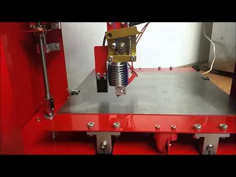
M303 - Start the PID calibration process [ M303 E-1 C8 S110 ]
where: E-1 - table, E0 - hotend, C8 - number of attempts, S - temperature.
M304 - Set PID parameters for the table [ M304 P1 I2 D3 ]
EEPROM - Internal memory of the microcontroller (not zeroed when turning off)
m500 - save parameters in EEPROM
m501 - read parameters from Eeprom- EEPROM
Filament
M200 – Set the diameter of the filament [ M200 D1.128 ]
M600 – Change the filament.
Speeds tab
Speeds - Adjustment of various speeds
Default Printing Speed - General print speed;
Outline Underspeed - Print speed of the outer parts of the model, as a percentage of the total speed;
Solid Infill Underspeed Solid Infill Underspeed, percentage of total speed;
Support Structure Underspeed - Support printing speed, percentage of total speed;
X / Y Axis Movement Speed - Maximum speed in X and Y axes;
Z Axis Movement Speed - Maximum speed along the Z axis;
Speed Overrides - Speed reset; Adjust printing speed for layers
Allow speed reductions down to
Other Tab
Filament Properties - Filament Properties;
Filament toolhead index – selection of a tool for editing material parameters;
Filament diameter — Diameter;
Filament price - The cost of a kilogram. From this value, the program after slicing will calculate and give the approximate cost of the model.
Filament density
Bridging block - Setting the printing of bridges;
Unsupported area threshold - Any "hanging" element of the model that is larger than the specified area will be recognized by the program as a bridge;
Bridging extrusion multiplier - Extrusion multiplier when printing bridges;
Bridging speed multiplier — Speed multiplier when printing bridges;
Use fixed bridging infill angle - Use a fixed angle for extrusion on bridges;
Apply bridging setting to perimeters – apply bridging setting to perimeters;
Horizontal Size compensatoin – horizontal size compensation;
Block Tol Change Retraction - retract setting for tool change. It is configured in the same way as the rectact in the first tab.
Advanced tab
Layer Modification – setting block for this process.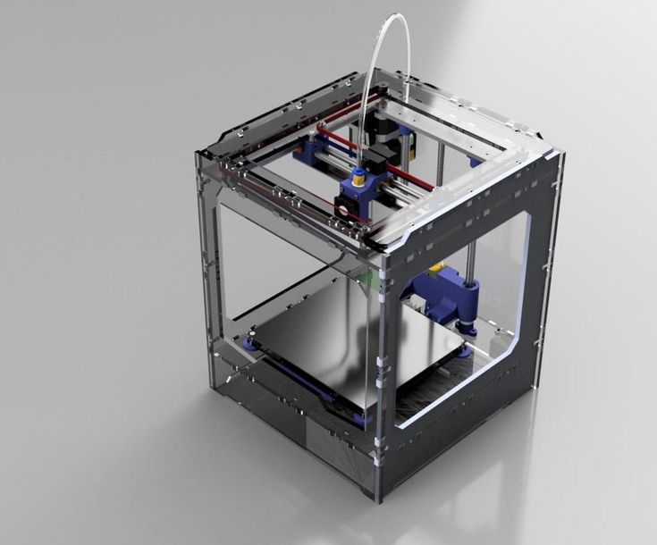 Adjustable from and to a specific Z-height.
Thin wall Behavior - Thin wall printing strategy.
External thin wall type - External perimeter strategy. Two options, print only the perimeter or use variable extrusion.
Internal thin wall type - Internal perimeter strategy. Compared to the previous paragraph, one more option has been added: print the usual filling.
Allowed perimeter overlap - Allow the perimeter to "overlap" each other by the set percentage.
Single Extrusions – Variable extrusion setting.
Minimum Extrusion Length
Minimum Extrusion width - Minimum Width
Maximum Extrusion Width - Maximum Width
Endpoint extension Distance - Specifies how many millimeters variable extrusion lines increase in length on one side and the other to increase the strength of the connection with other fibers.
Ooze control behavior - Additional self-flow settings
Only retract when crossing open spaces0003
Force retraction between layers
Minimum travel fer retraction
Perform retraction during wipe movement Only 9007 wipe 9002 wipe9003 extruder for outer-most perimeter - Wipe nozzle only on outer perimeters
Movement behavior - movement correction
Avoid crossing outline for travel movement – avoid crossing the part when moving.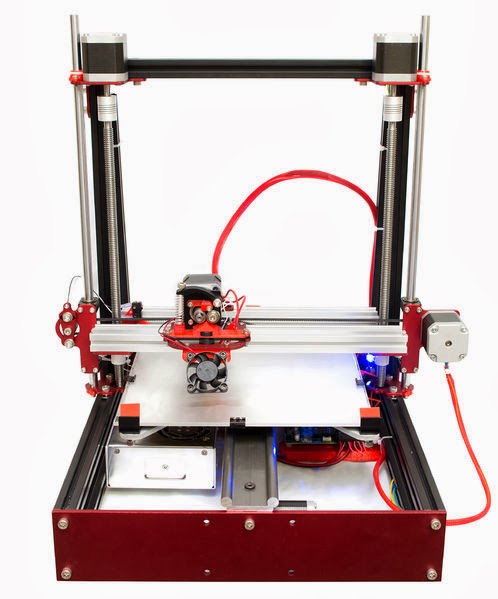 Even if the stroke is not enough, the movement will still reach the plastic to the model.
Slicing behavior - Additional slicer parameters0003
Merge all outlines into a single solid models - Remove extra holes from the model
Multiple processes at the same time
To run multiple processes in a single 3D print setup, you need to create them in the profile list. After creating, you need to go into the advanced settings of each profile and select the distance of this process operation relative to the Z height using the start printing and stop printing parameters in the Layer Modification block.0003
Check G-Code
Block animation - Allows you to start the animation of the 3D printing process and select the animation speed.
Block Control Option - allows you to selectively display lines or layers of 3D printing.
Block Line Range to Show - Allows you to select the display range from the previous block.
Block Show in Preview – preview display mode. build table will enable or disable platform display, toolhets will turn on or off the display of the tool, retraction will turn on or off the display of retract points, travel moves will show where the idle moves will be.
In this block, for me personally, the last paragraph ( travel moves ) is the most useful. Why? Because if you incorrectly set the retraction parameters for your 3D printer, then in these places there will be
The red lines are just the extruder idle lines.
Addition
Working with a polygonal mesh
On the Mesh tab you put on the settings for working with a mesh.
A common problem I had was opening a file incorrectly in terms of mirroring. Check this moment!
Another very useful feature for multi-family printing: copies of the model on the table. I saw one of my students, in order to place 4 pieces on the table.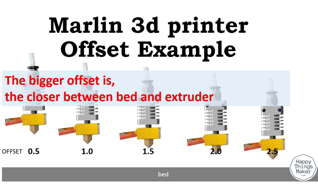 identical models, 4 times dragged these models into the window. So I decided to focus on this moment. To make several copies of the model and place them on the same table, you need to use this function.
Next, you need to take how many copies you want to see on the table.
Disadvantages
Alas, it is not yet possible to set the layer height for a particular section of the perimeter in the program. For example, to print the outer wall with a layer height twice as thin as the inner perimeter. I even wrote a letter in support of Simplify3D. And they gave me the answer! See bottom of the page.
Conclusion
The best program, but if there is a better one, write to us at [email protected].
If you have any questions, write in the comments to this article. I'll try to answer.
P.S Simplify3D gave the answer. And I really liked him. Although completely, but partially it solves the issue:
Hello,
Sorry, not at this time.