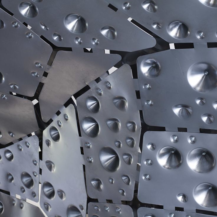
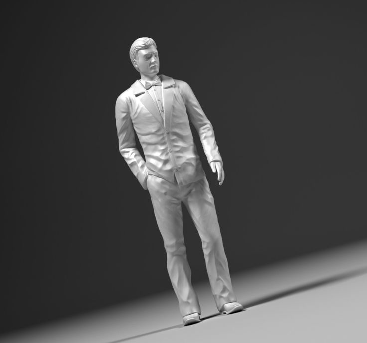
3D printing textured surface
3D printing of bioinspired textured surfaces with superamphiphobicity
Changyou Yan,ab Pan Jiang,ab Xin Jiac and Xiaolong Wang *acd
Author affiliations
* Corresponding authors
a
State Key Laboratory of Solid Lubrication, Lanzhou Institute of Chemical Physics, Chinese Academy of Sciences, Lanzhou 730000, China
E-mail:
wangxl@licp. cas.cn
b Center of Materials Science and Optoelectronics Engineering, University of Chinese Academy of Sciences, Beijing 100039, China
c School of Chemistry and Chemical Engineering, Shihezi University, Shihezi 832003, China
d Yiwu R&D Centre for Functional Materials, LICP, CAS, Yiwu 322000, China
Abstract
Natural superwettable surfaces have received extensive attention due to their unique wetting performance and functionalities. Inspired by nature, artificial surfaces with superwettability, particularly superamphiphobicity, i.e., superhydrophobicity and superoleophobicity, have been widely developed using various methods and techniques, where 3D printing, which is also called additive manufacturing, is an emerging technique. 3D printing is efficient for rapid and precise prototyping with the advantage of fabricating various architectures and structures with extreme complexity. Therefore, it is promising for building bioinspired superamphiphobic surfaces with structural complexity in a facile manner. Herein, the state-of-the-art 3D printing techniques and methods for fabricating superwettable surfaces with micro/nanostructures are reviewed, followed by an overview of their extensive applications, which are believed to be promising in engineered wettability, bionic science, liquid transport, microfluidics, drag reduction, anti-fouling, oil/water separation, etc.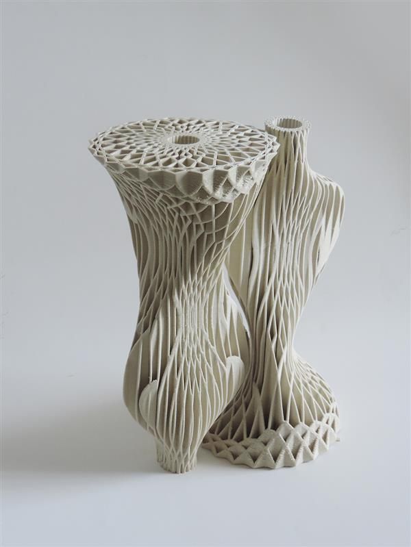
- This article is part of the themed collection: Recent Review Articles
Technical Tips for Creating 3D Print Textures and Surface Materials - Updated 2020
Color, pattern, and surface textures are the first things we react to when evaluating a product. For consumers to connect to 3D print products, 3D print textures need to be carefully considered and created as a part of the design process. This has been a challenging part of the 3D design process. Fresh from the Project Captis episode, Tom Hazzard and Tracy Hazzard look back on the previous episode on technical tips for creating 3D print textures and surface materials and provide an update on how far the design process has come. They talk about the tools and improvements that are coming out to help apply textures to 3D models easier.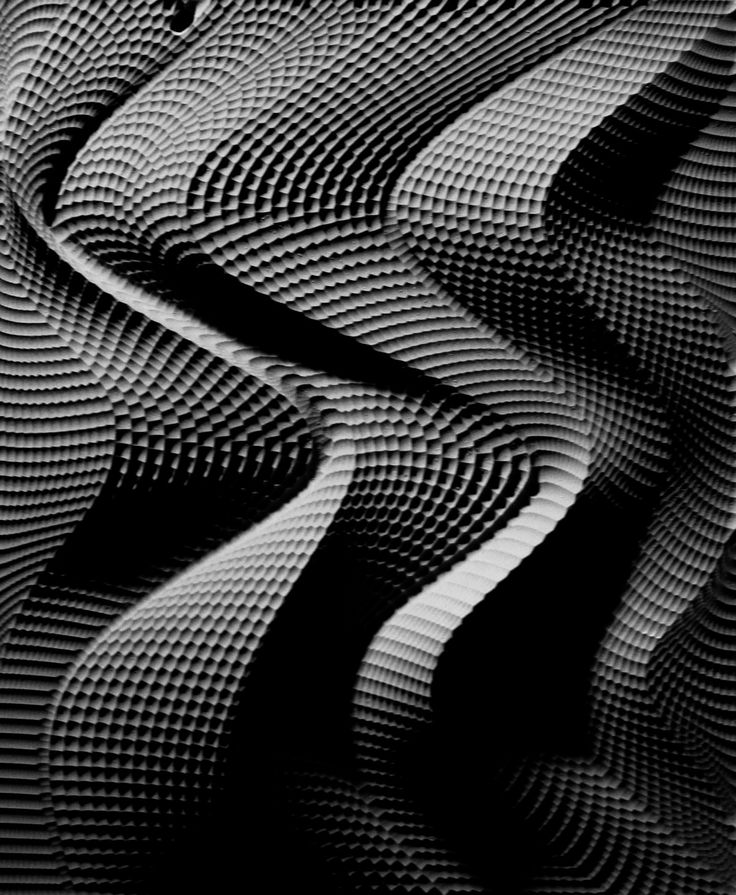 In praise of the old school techniques, they then discuss why getting familiar with the different 3D manufacturing processes can inform you to create better 3D products that people will love.
—
Watch the episode here:
Listen to the podcast here
Technical Tips for Creating 3D Print Textures and Surface Materials
We’re going to be talking about an old Tom Hazzard episode. Sometimes we do episodes that are technical and Tom takes over, and this was one of them in our series. It was technical tips for creating 3D print textures. It was a request from an audience. I thought it’s a great one to follow our Project Captis introduction where we got to learn more about what was going on there with Josh St. John. It’s amazing how much easier it might be to create some of those things. I keep thinking about that as we were doing that episode.
This is one of my favorite episodes with WTFFF in the past. Sorry about that because Tracy wasn’t on it, but here’s the thing.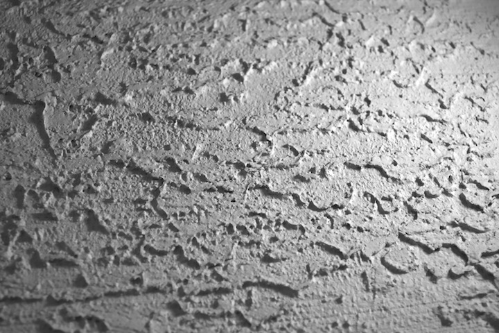 I geek out on these tech things and when it comes to how to use your CAD files to achieve what you want to. One of the things about 3D printing that’s always been the case, and I think it still is, about every different 3D printer you could possibly use or buy to print your objects. There is a telltale sign in the surface quality of the part that speaks to how it was made, whether it’s powder bed fusion of some kind.
That goes beyond 3D printing though. You can tell when something’s injection-molded, rotationally molded. I feel like all of our manufacturing techniques for the most part have a distinctive signature as to how they’re made. It probably might take an engineer to analyze and pick up was this made this way or that way, sometimes. We may not be able to as a consumer identify it, but we have a quality understanding of this is what rotationally molded toys are like or garbage cans or whatever it is. We have a sense of that. There is a sense of that with 3D printing as well. That’s something that we have worked on throughout our careers and probably Tom’s more sensitive to it because I’ve been pushing him on surface sectors. It’s important to me. I love the idea of when we can transcend the manufacturing process of any kind, no matter what that is, whether it’s 3D printing or injection molding. I want to transcend that and I don’t want it to be obvious.
A surface texture is a wonderful way to create a beautiful object that is not a big billboard saying, “I was made this way.” It can transform an object to the point where, especially even in 3D printing, you may question, “How was that made?” That’s a good place to be because that says you’re looking more at the beauty of the object or what it’s meant to do then you are how it was made. My favorite is when they go, “What is that material? Is it plastic? Is it metal?” I love it when they can’t tell what the material is. That excites me even more. We’ve done a good job of transcending the process and the material options of what we had to make it from too.
What we’ve been learning through this special series with HP is that there are new tools. We’ve talked about some already, and we’re going to talk about some more in some upcoming episodes. There are new software tools. Things have advanced when it comes to textures and application of textures as it should have. The industry community continues to make improvements there and it’s been done so that now there may be a lot more easier ways to apply textures to a model you’ve created and not have to do it so much the hard way. I talk a bit about some of the more technical, conventional, old school ways to create surface textures in your models before 3D printing.
The Project Captis does sound like it’s going to make it a whole lot easier for you to capture it and figure out what that texture is and then re-engineer that all over your part or put that out and apply it. That’s fantastic that those things are there. We thought that this episode was a good one to pull in for you because sometimes knowing exactly how to do something at its old school hard way gives you more insights into how to apply it and utilize it to best achieve the ultimate goal. That is to create an object that people want, that people love, that they want to use or understand how to use if we’re trying to make something functional.
In every different manufacturing process, there is a telltale sign in the surface quality of the #3Dproduct that speaks to how it was made. @hp @zbyhp Click To Tweet
Some people reading may say, “These guys are old school. They use the new tools and don’t worry about how you have to do it the hard way.” Probably, there are arguments to be made that there’s value for each of those schools of thought. I believe that if you’re going to develop a quality product that has integrity, that meets all the goals of the manufacturer, the user, the market, it considers everything. You’ve got to be intimately familiar with all of the different manufacturing processes, their limitations, their pros or cons, all these things in order to do a good job at that. To me, I think similarly, even if you’re going to use an advanced tool to apply textures, it’s important to have a good understanding of what it takes to create them by hand or the hard way through CAD yourself. In order to then not only appreciate what new software does but they able to be able to use it in the most effective way and not have it cause problems in the way of what you’re trying to do.
Sometimes we learn that the process we had to use to apply 3D print textures in the past were not the best ways. Now, we can achieve even more textures, more techniques, and more things that we couldn’t do before, which allows us to actually go beyond in the design and creative process. We find that all the time in manufacturing. When we’re manufacturing something, we’re limited to the mold. It allows only these levels of textures and these types of textures. We also have to be cognizant of that on our end when we’re designing that we don’t simulate something that we can’t create. Thinking about those two things, that’s one of the reasons why we look at and deeply understand how I want to create something, how it needs to be created. That will also help me understand whether it’s limited and it’s an opportunity for printing it, in this case, 3D printing it, or making it and manufacturing it ultimately. Is that possible? Does it do what it’s supposed to do? Is it going to be textural enough, hot enough, create crumb catchers like we used to call them? If you create them too deep, they create come crumb catchers where you catch dirt and crumbs. We want to avoid those things. Learning that from an old school enough from a texture application point of view is helpful.
Not only that, you also want to remember that because you can do something in 3D printing doesn’t mean you should do it or doesn’t mean that it’s going to be easy to manufacture in another way in another process. If you’re designing a part that’s going to be digitally manufactured forever, great. Use whatever’s available to you in that process and don’t worry about it. Eventually, this is a part that’s going to be injection molded, it’s going to be thermal formed or it’s going to be a machine out of metal instead of 3D printed in metal, you’ve got to know what those limitations are and realize that you could create this beautiful texture.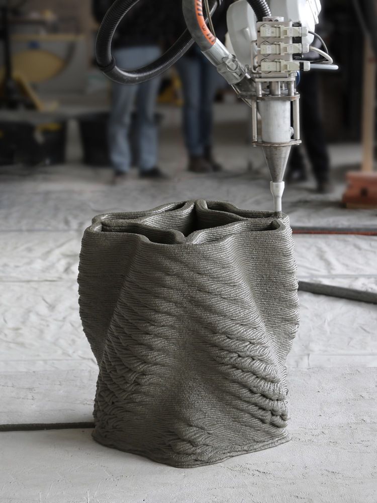
If it’s going to create an undercut or a problem in the mold, you’re not going to be able to remove it from it. You’ve got still real-world considerations for manufacturing. The consumer doesn’t end up carrying how something was manufactured. At the end of the day, all they care about is do they like the object? Is it attractive to them? Do they want it? Does it do what they expect it to do after they buy it? Ultimately, they don’t care if it’s injection-molded, rotational molded or 3D printed. It makes no difference. You’ve got to make sure that you don’t cause a problem by your lack of understanding of how some things might happen or how a texture might be applied.
This is why it’s Tom’s episode. We’re going to talk about those technical tips. Why don’t we go ahead and go to the episode where he answered the question on how to create 3D print textures.
Technical Tips for Creating 3D Print Textures and Surface Materials — originally aired on March 28, 2017
The subject is surface textures.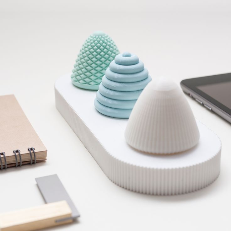 This is written by Casey Snyder. Casey, I appreciate you writing in. Casey writes and throwing out there an idea for a show topic that many people might benefit from. The idea of adding subtle or maybe shallow surface textures to 3D models for 3D printing. Casey is looking for methods that would preserve an object’s basic geometry. Casey primarily uses SOLIDWORKS and would love to be able to knurl, fish scale, dimple, etc. over curved on irregular surfaces. Casey realizes it might be a tall order in SOLIDWORKS and has attempted surface textures in Mudbox and Blender, but feels it’s too uncontrolled. It always tends to alter the part in ways that were unintended. The idea here is to break up the layer lines, the visible vertical layer lines on a part, but ideally still maintain the core geometry. It’s actually a really good question and issue that Casey is having. I have had the same issue many times myself and I’m sure many of our audience have.
I’m going to tell you what I’ve done from my perspective. I’ve had the exact same issue. This is a tough one. Let’s talk about knurling first of all, because knurled surfaces are pretty unique in the world of geometry. Knurling is a way to create a diamond patterned grip surface usually done on metal, although I’ve seen it molded on plastic. It’s a process that has existed as long as metal lathes have existed. There’s an actual tool called a knurling tool. It’s quite fascinating because if you turn a piece of metal and let’s say you want a handle at the end. The easiest example I can think of is if you’ve ever used a vise grip pliers-type of tool, the Vise Grip brand. There are others that are not their brand. That’s the easiest example I can think of a knurled surface. If you don’t have one, next time you’re in Home Depot or Lowe’s or any hardware store, you can find one.
A vise grip is an adjustable pliers, it has an adjustable grip of a pliers made of stainless steel of some kind. They have this screw in one of the handles that you can adjust in or out to change that adjustable grip range of the pliers. At the very bottom of that, what you actually turn has a bit of a diamond patterned grip on it. That is a knurled surface and it’s formed with a tool called a knurler. The idea is that big screw is a screw machine part. It’s produced on a lathe. They’ll cut the threads in it and then have this little pronounced handle at the bottom. That starts out as a flat radius surface. This knurler tool, which has two different wheels on it, they’re really a cutting tool and a forming tool in one. If you push it in as the part is rotating slowly on the lathe, you push the knurler into it and it simultaneously cuts and digs into that surface and reforms that steel into a diamond shaped pattern which makes it grip really easily. Obviously, the intension was to make a surface that’s easy to grip.
When it comes to creating something like that in a 3D printed part, that’s a little different because obviously we’re not forming material as it’s rotating in the same way. You would have to actually create it in geometry. Here is where you have to be much more precise in creating your geometry than you would using a knurling tool. It’s an interesting example and it’s part of why I wanted to talk about this today. There are many things that have been created in standard manufacturing since the first industrial revolution. Manufacturing methods, decoration methods, manipulation of material methods that are built around how things are traditionally made, in this case a lathe turned part.
The knurler is fascinating because no matter diameter or part you want to knurl, no matter how large or small that diameter is, the knurler tool will work every time. It’s not something you program in to a process to make sure it all matches up. It just does it. It’s hard to explain why that is. It’s a fascinating aspect of physics and geometry and manufacturing. When we need to make something like that and 3D print it, you have to predetermine that pattern and the 3D printer has to actually go and make the geometry. It’s an entirely different process. It’s much more difficult to get that repeating pattern to repeat perfectly around the circumference of the part. Let’s say, in this case, you’re going to do a round cylindrical type of part with that kind of texture. You have to predetermine that and make sure that diamond pattern will absolutely match up and have consistent gaps and distances with no overlapping when you get around that entire 360 degrees of the part.
3D Print Textures: Become intimately familiar with the different 3D manufacturing processes to develop a quality product that has integrity and meets the goals of the manufacturer, user, and market.
It’s not always easy. You’ve got to know what your circumference is, design your three-dimensional diamond pattern to actually meet up perfectly around that distance and then create some geometry that you’re going to probably use a tool like an array or revolve tool or there are a number of different tools you can use to achieve this in CAD.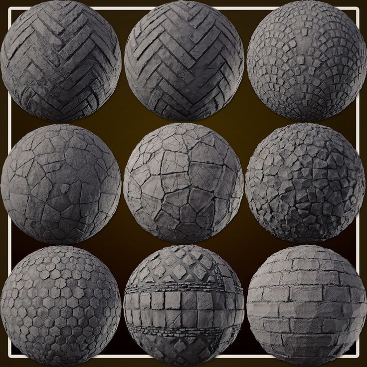 You’re going to either cut into or add to a three-dimensional surface in that pattern you want. It’s an entirely different process and it’s not easy. It’s not like you can just go, “I’ve made this cylindrical surface, go add a knurled surface.” Maybe some of the programs out there, some of the maybe higher end CAD programs, especially ones where you can specify threads and say, “I want an M6 thread on this part,” and it’s going to know what to do to make that thread or any one of the standard thread sizes you can do. I don’t know if any of them do knurled surfaces the same way. They may because it’s such a common thing. Let’s say for a moment that they don’t have that automated, it’s a hard thing to go and model in geometry.
What I would do in that case, when making a knurled surface, I would make my cylinder what I want. I would probably use either a Helix or a spiral geometry tool to create a curved path that is in a spiral formation. Spiral is probably the right one. You can define the number of turns that spiral does around the object and then over a given height distance, and then I would take a V-shaped or a triangular shaped, two-dimensional shaped and then extrude it. Extruding may not be the right term for following a path. Different programs call it different things. I use Rhinoceros primarily, so that would be sweeping a rail with a certain shape. It would create this V-surface in an object that is a continual, spiraled extrusion of a triangular shape or a V-shape. You’d have the point going in toward the center of the cylindrical object that you want to cut away from. You may have to adjust where your shape is relative to the path you’re sweeping it on or extruding it along. But you can get it so that you’re going to cut in to the cylinder you’re doing. You can do that with a spiral in one direction and then a spiral in the other direction to crisscross it and create your diamond shaped pattern.
It’s going to be a multistep process. It’s not something that’s going to work really well in your parametric programs like SOLIDWORKS. Casey, I hate to tell you this, but the way parametric programs and how they work, they’re not made to handle this type of operation in an easy way when you’re creating something in your mind from scratch.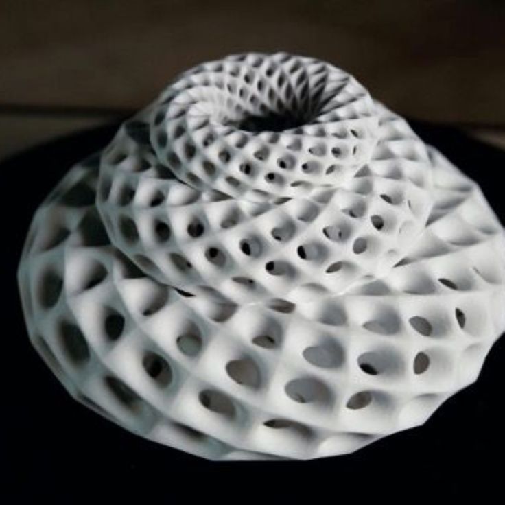 They definitely would want it to be some kind of a program or script that’s going to somehow define this geometry that you want to create and have something programmed in. You need it to be a tool that already exists to do this type of thing. I don’t use parametric programs very often for this exact reason because some of the forms, shapes and textures that I want to create are not that easily defined in parametric programs. I would be beating my brains out if I try to do it all the time. Creating something in more of a program like Rhinoceros or even Blender or some of these other programs that allow more freeform geometry creation would be easier to do it in. It’s still going to be a very manual process. There are few programs that can help you do it in an automated way.
Moving away from knurling, let’s talk about some of the other things. Let’s say you want a dimple texture, like you wanted to make a golf ball and have dimples on a golf ball or any other really overall textured surface.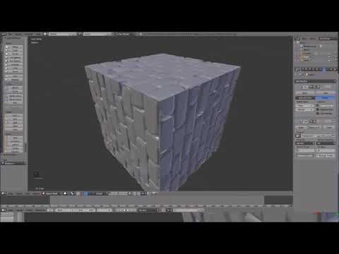 Mudbox actually is a good tool to do that. I have tried it. I actually have Mudbox and that’s what I would do. I would create my geometry in one program, bring it into another like Mudbox and apply surface texture to it. There are ways to do it so that you don’t alter the underlying geometry but it’s still not easy. I know certainly there are ways you can mess up your underlying geometry.
Here’s the other problem you’re going to have. Once you bring it into Mudbox, if you want to bring it back into SOLIDWORKS, I believe you lose all your parametric properties at that point. Exporting something from SOLIDWORKS into a Mudbox program or Rhinoceros or other program, you’ve got to be taking what is very smart geometry and making it dumb. That’s what we call it. You’re going to be making it into a dumb solid in order to do this surface texture modification to it. You need to have completely finished all of your geometry in the parametric program. The very end process is what you want to be doing the texture in. You don’t want to be having to then go back and do other things to it.
If I were you, and I were doing something like this, completely finish designing or engineering your part in SOLIDWORKS, save that file in SOLIDWORKS because you may need it again to do a different texture or if you take the texture too far and hurt it, you’re going to need to export it again. Then make that be the last step in the process, putting a texture on it and go right to STL for 3D printing. That process makes sense. It’s like a one-way street though. You are not going to be able to come back.
I have another example. Not to push Rhinoceros, it’s just what I have the most experience in. Rhinoceros is a program that there are a lot of companies that write and make plug-ins for it. I actually purchased a plug-in, pretty darned expensive one, I’m afraid to say. It was about $1,000, which was craziness unless you’re a professional. There’s a plug-in called RhinoEmboss. I bought that plug-in specifically to do this exact thing.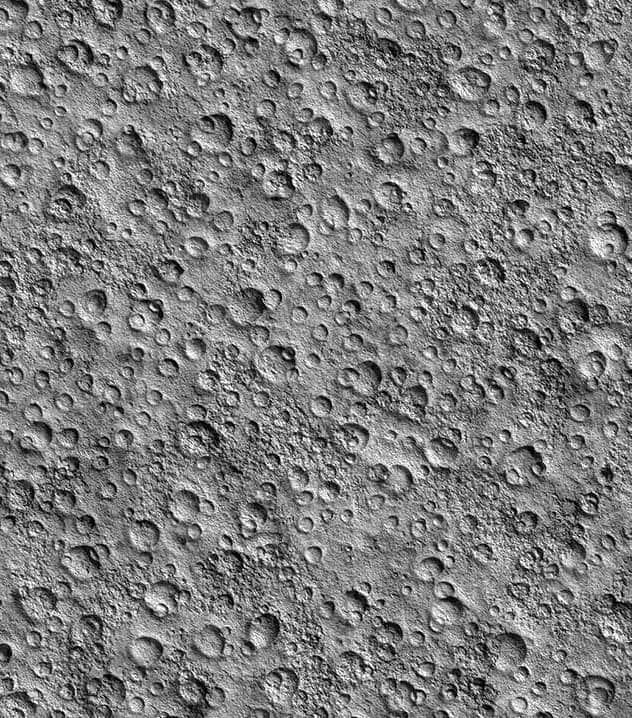 Take geometry that I had created and then apply textures to it. You can apply any kind of texture you can imagine by using a 2D image, like a JPEG or something, of the texture. Any photograph that you like, you can load it in and almost project it over the top of an object you’ve made and you can mask-off areas you don’t want to be affected and essentially paint, if you will, or draw with a brush or whatever, in the areas that you want the texture to be applied.
You can choose if you want it to be embossed or debossed, or in another way, if you want it to be added texture away from the surface you’ve created or if you want it to cut in, basically making something convex or concave. You can choose and decide that. It allows you to create very unlimited kinds of textures. I think Mudbox does a similar thing. I think also ZBrush I’ve seen has that same kind of functionality but it’s not in the world of parametric modeling. In every case, every example that I know of that I’ve used, it’s going to be an end-use process, like I said, a one-way street. You don’t want to do that until you believe you don’t have any other modifications you need to make to your part because it’s going to be extraordinarily difficult to do that after the fact.
The #3Dprintindustry community continues to make improvements, so there may be easier ways to apply #3Dprinttextures to your #3Dmodel. @hp @zbyhp Click To Tweet
RhinoEmboss, lots of other great tools for manipulation, creating relief structures, that’s what we’re talking about. I come from the art and design world, even though I do engineering of things. I’m not a degreed engineer. In the art and design world, we’re talking about relief here, which is really reliefs have existed as long as art has in the form of sculpture. You’re talking about pushing and pulling material, creating different shapes and patterns and all kinds of different details. You can create relief in many different ways with certain different programs applying interpretation of 2D images to create three-dimensional geometry. You can change the degree of depth through which it goes and how hard or soft it’s created. You could change the scale of these patterns. That’s the best way that I found.
Here’s the thing. It takes some work to learn how to do it. If you want to create 3D printed parts that are built layer by layer and completely disguise those layers, this is the best way to do it and applying it to your vertical faces or surfaces that exist on your part, especially if you’re making a nice object. Let’s say you’re making a lampshade. If I was making a golf ball for instance, I would create the pattern of dimples, I would use standard commands in CAD program. I wouldn’t be using a texture interpreted from a 2D image and project it on to it. Dimples are probably a little easier because you can do a polar array around something that’s round or even spherical of a pattern that is a half drop repeat. I think golf ball dimple shape is a bit of a half drop repeat that is repeated radially around the sphere of a golf ball. I think it’s an actual definable, repeatable pattern that you can do.
If you’re going to do anything that has that definition, create the three-dimensional shapes that you either want to add or subtract from another object and use a command like an array, either rectangular or a polar, creating that repeated pattern, then use a Boolean operation to add it or subtract it from what you’re doing. That’s the only other way. Using SOLIDWORKS, that’s going to be probably the most practical way to try to do it, especially if you want to maintain all of your constraints and your smart geometry.
I would be interested to know, once you did that in a SOLIDWORKS or even Inventor or all these other programs that use parametrics, once you create that dimpled pattern, if you ended up making the part larger, I wonder if it might actually stretch the dimples. I don’t think it’s going to create more for you. These are the complexities and challenges with parametric modeling versus other kinds of modeling.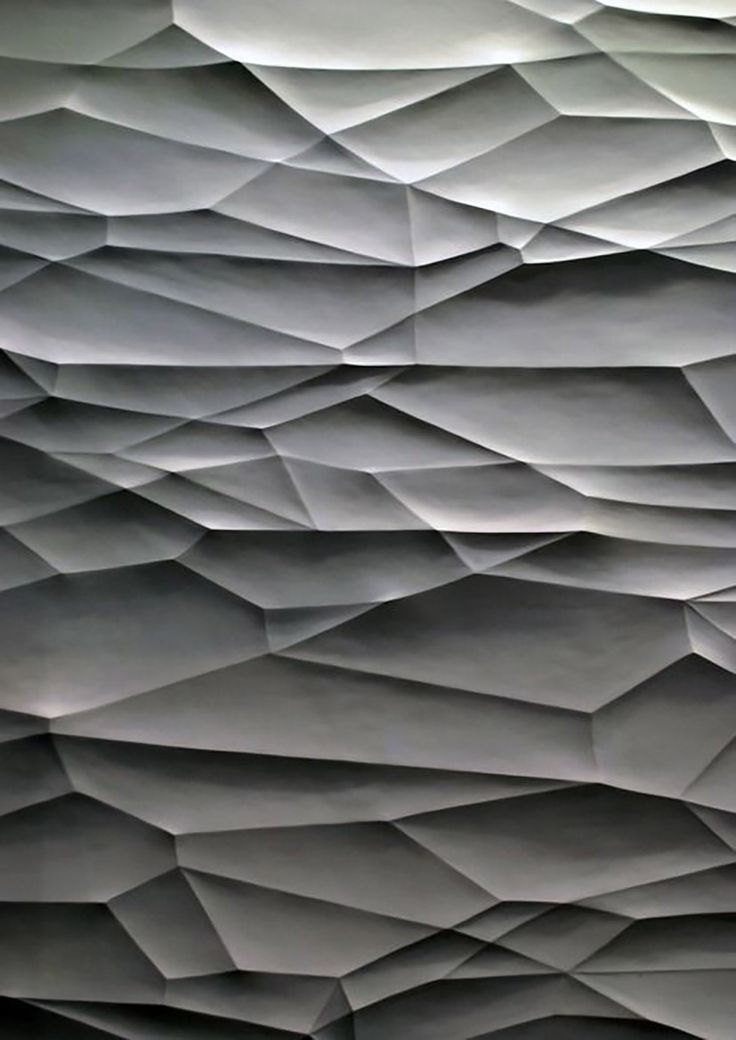 This also points out the main reason why there are many different CAD programs out there. There’s not one absolute right or wrong way to make an object. The more engineering type of programs are wonderful for creating geometry simply and being able to make changes in that geometry without having to rebuild the whole part. You’re running up against where they become limited and it’s more on the artistic pattern decoration side of things that they tend to fall a little short or just are not able to achieve some of the same things as the more artistic programs. Then you have the more artistic programs.
ZBrush as an example is way on the far end of artistic. You can create all kinds of wonderful organic textures and shapes. You can’t be very specific in that program other than generally how big or small something is. You’re not going to have a great degree of precision. If you need to make a change to something, you may have to largely remake a large part, if not the entire part. There are pros and cons to every software.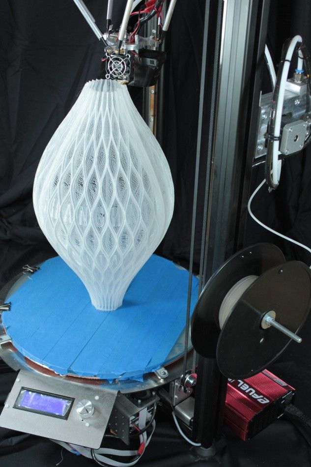 That’s why I don’t think there’s a good or a bad software out there. In terms of CAD creation, there are different kinds and different programs have different better capabilities or not so great capabilities in certain areas. It depends on what you’re trying to make. We always say in WTFFF, it’s all about the ‘what,’ what the FFF do you want to make? Knowing that ahead of time will help you out.
It doesn’t help you a lot if you spend a whole lot of time learning SOLIDWORKS, you don’t know these other programs so well and then you need to do more, I guess, less geometrically rigid creations because you’re going to have to learn another program or at least learn enough of it to use it. You can do that. I use Photoshop, probably about 5% of all the tools in Photoshop I use. I use them for what I need to and I’ve learned how to do it and that’s it. I don’t try to do everything within Photoshop when I’m working with images. I’ve got a couple of different CAD programs and I use some more than others.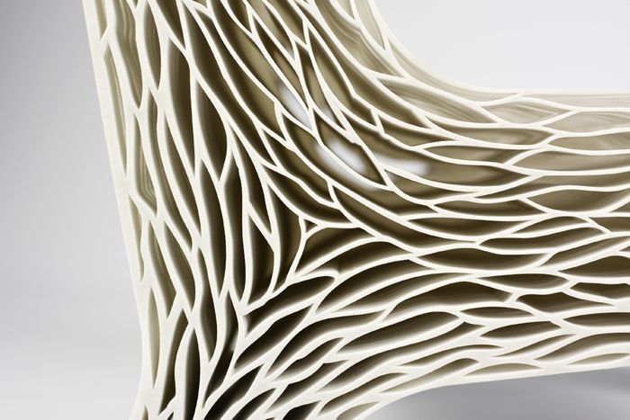 It depends on what I’m making.
Unfortunately, I don’t have the absolute silver bullet here as the absolute answer for you, Casey. I’m sorry about that. I wish I did. It’s a great question, it’s a great discussion. There are probably some new tools out there I don’t even know about. We’re always looking at new software. We’re always trying them out, reviewing them from time to time. I don’t know everything that’s out there, but if there’s something better out there, I bet one of our audience knows and I’d love to hear about it. Please share with us. If you’ve got what you think is the best way to do it, or even if it’s not the best way, it’s just a way to do it, reach out to us anywhere on social media, @3DStartPoint. Thanks so much for reading. I hope this episode was helpful. We’ll talk to you next time. This has been Tom on the WTFFF 3D Printing Podcast.
Get Even More!
10 Tips Webinar
Resources:
- Josh St. John
- SOLIDWORKS
- ZBrush
- Mudbox
- Blender
- Rhinoceros
- RhinoEmboss
- Inventor
More About HP:
Capture and Create with Z by HP, Inspiring you for your next creative breakthrough with the Z portfolio designed and built to improve the way you create.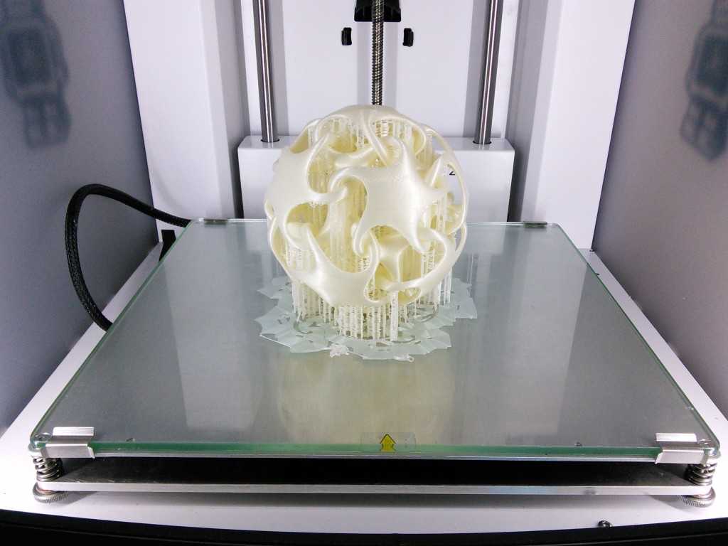 Discover the latest Z Book to help you with your latest creative project.
Experience your design with HP Multi Jet Fusion technology and solutions reinvent design and manufacturing, unlocking the full potential of 3D printing and bringing down the barriers of 3D printing adoption across industries through materials innovation. For more details about Multi Jet Fusion technology click here.
Join the WTFFF?! 3D Printing movement today:
[DISPLAY_ULTIMATE_SOCIAL_ICONS]
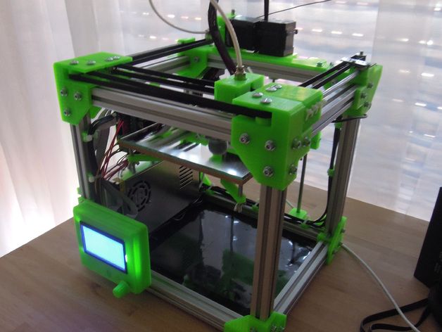
Course of lectures on 3D printing. Lecture 6.
Lesson 6. Print optimization.
Once, when a queue of orders suddenly loomed before my eyes, I had to look for ways to speed up printing in various ways. The printer has already been overclocked, the potential, as they say, has been selected.
Modification of the seal itself remains. The options are: print less plastic, print faster, print thicker, reduce nozzle idling, and reduce the amount of post-processing required.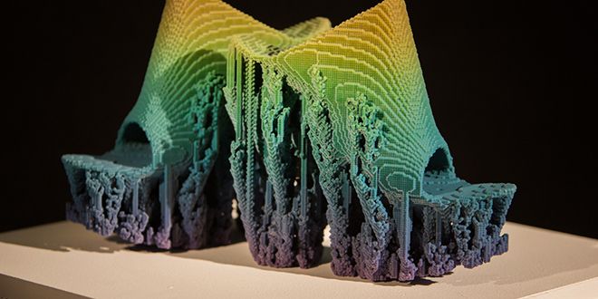
1. Print less plastic : FDM printing is a unique technology that allows you to make thin-walled products with a minimum of infill. Plastic is saved, however, strength suffers. If there are no high requirements for the strength of the product, then the filling and wall thickness can be cut to a technological minimum.
In the Cura slicer, these parameters are set in the Shell block:
Wall Line count (or Wall Thickness, if needed in millimeters)
Top Layers and Bottom Layers (or Thickness, if needed in millimeters)
Infill is adjusted in the Infill block
Infill density - infill density.
In addition to density, the strength and amount of printed plastic is affected by the infill pattern.
Initially, filling patterns are designed to withstand the load applied to the product from different sides.
- Concentric: Elastic 2D
- Lines: Fast/Elastic 2D
- Zig-zag: Fast/Elastic 2D
- Grid: Strong 2D
- Triangles: Strong 2D
- 9000 TRI-HEXAGON: Strong 2D
- Cubic: Strong 3D (less Cubic consumption)
- Strong 3D
- Octet: Strong 3D
- QUARTER CUBIC : durable 3D
- Cross: Elastic 2D
- 9000 9000 : Elastic 3D
- 9000 Gyroid: Elastic 3D
Two-dimensional fillings have increased strength along the Z axis and relative elasticity along the XY axes. Don't forget that the second purpose of padding is to support horizontal and convex surfaces. To obtain smooth surfaces without defects, more layers are required for more hollow products.
Adaptive layers
The second most effective way to speed up printing is the adaptive layer thickness mode. Surfaces that do not contain small changes in shape can be printed in a thicker layer without loss of quality. To do this, in the Cura slicer, include Use adaptive layers . The mode consists of the following parameters:
Adaptive layers maximum variation - the amount by which the layer size can differ from the parameter Layers height
Adaptive layers variation step size - the step size with which the layer thickness adapts to the model detail.
Adaptive layers threshold - aggressiveness of layer thickness adaptation.
Nozzle layers range from 20 to 80% of diameter without major loss of strength. Applying thicker layers more aggressively speeds up printing significantly.
Dividing the model into areas of specific print settings
Multiprocess is a technique required to print a product with different print settings on different areas/layers. This technique has already been described in Lecture No. 4 for the needs of manual creation of supports. Above the model, a so-called. Zone of special parameters. And this zone is given one of the functions through the 'Per Model Settings' menu - in this case, the function is called Modify settings for overlap with other models - Special print settings for sections of models that fall into the Zone of special parameters. Through this interface it is possible to set, for example, speed parameters and filling parameters.
So areas with high detail can be printed slowly, and areas with low detail can be printed thicker using adaptive layers and at higher speeds using the Custom Settings Zone. In addition, the same technique can correct other difficulties of the printed model.
The Multiprocess technique can also be used vice versa to enhance the detail of the model: a model with low detail can be printed quickly, and a separate area with fine detail can be printed slowly and at a lower temperature according to special parameters.
Tree support printing
Support printing is a separate art form that requires your own experience. The standard algorithm for generating supports in Cura is not optimal and in some cases can be replaced by a more efficient, but demanding to tune, algorithm for generating branched tree-like supports.
Please note that when Tree Support mode is activated in Cura slicer, the parameters of the Support block become available, despite the disabled Generate Support parameter. These parameters also partially affect the branched support tree.
This is where my knowledge of acceleration ends, and I turn to the nuances of printing known to me, which I consider important to voice.
Spiralization mode
Spiralize Outer Contour - printing mode when the product is printed with one continuous thread in one layer. Allows you to quickly make vessels, pots and some specially designed models. Small nozzles can hardly cope with the task of creating strong and airtight vessels.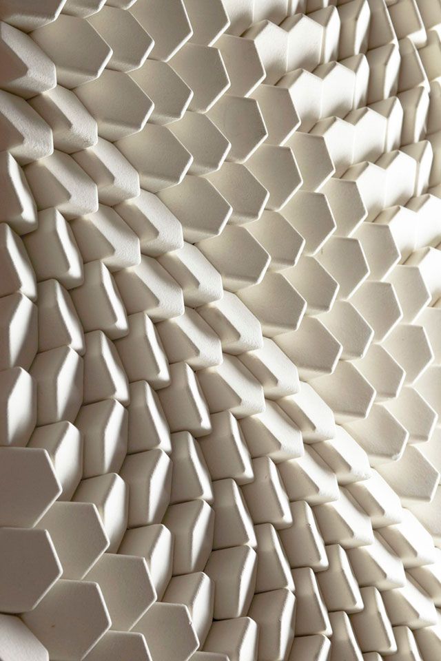 One solution is to over-extrusion, such as Flow 150% or line width 200% of the nozzle diameter. This will create a thicker filament and have a chance of making tight walls with a thin nozzle.
Mold creation mode for casting
Mold creation for castings - Mold - function for generating a casting mold based on a loaded model. It has a number of parameters that change the shape of the final product.
Surface texturing mode
One of the texturing modes - Ironing - we reviewed in the last lecture
The second surface texturing function in Cura - Fuzzy Skin processing.
Optimize Wall Printing Order parameter
The standard displacement calculation algorithm implies printing different functional elements in turn. For example, infills are printed first, then inner walls, then outer walls, and so on. The wall print optimization mode allows you to reduce the number of movements and allows you to print contours located closer to each other, but having different functional purposes. On some models, however, this mode, on the contrary, increases the print time. Check the cutting result carefully.
Last but not least, optimal layer thickness.
The default Cura slicer offers layers in multiples of tenths of a millimeter. To match the diameter of the nozzles. However, on some printer models, at a layer height of 0.1mm, this results in a slight over-extrusion every few layers. I say right away that the 0.2mm layer is not susceptible to this disease.
The reason is as follows:
To create a gap for the next layer, the Z-axis motor must turn the drive screw a certain number of microsteps. However, due to the design features of the motor, not all motor microsteps are identical. Some microsteps are smaller than others. Therefore, for the stability of the gap, it is desirable to fall into the same microsteps. The calculation of the optimal layer thicknesses for the printer is done as follows:
Standard Z-axis motor makes 200 full steps per 1 full revolution.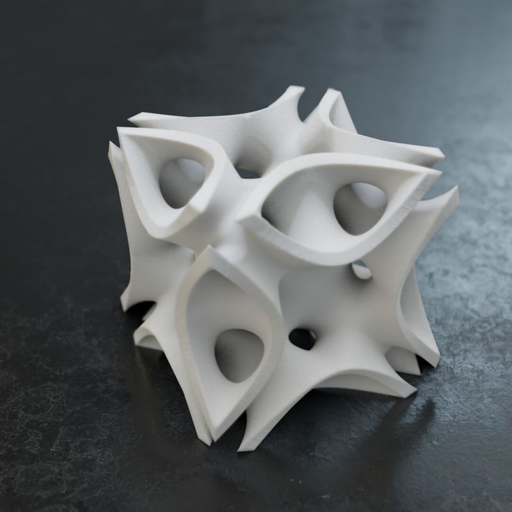 For a T8 drive screw, a full turn is identical to 8 millimeters of lift. From this it turns out that 1 full step corresponds to a nozzle lift of 0.04mm. To compensate for this effect, I recommend setting the height to a multiple of 1 full step of the Z motor. For my printer, the layer thickness should be a multiple of 0.04mm. For example, 0.12mm instead of 0.1mm.
This slight layer change allows you to print faster without any visible change in product appearance.
That's all for me. The optimization methods described in this lecture made it possible to double the time for manufacturing parts. Further significant production speedups were achieved simply by better printing with fewer artifacts and defects.
Finally, I want to tell you how a printer with a single extruder print products in several colors.
The first way - butt welding of multicolored filaments . For the convenience of the process, you can print the filament holder.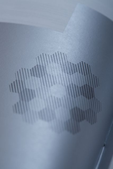 The second way - printing with gradient filament . The color of the thread gradually changes, the products are iridescent. This method is relevant for large products.
And finally the third way - semi-automatic filament change on certain layers .
The method is based on Kura's ability to pause printing on a layer with a given number and allow the user to change the filament. First of all, the limitations of the applicability of this method: you can only print entire layers or groups of consecutive layers. For example, to make colored inscriptions on the prepared site.
When the model is ready for printing, using the layered view, you can determine from which layer you want to change the color of the filament by number.
The tool to pause printing on a specific layer is found in the Cura slicer under Extensions- Post-Processing - Modify G-code.
All that remains to be done is to add a script to pause printing at a certain height.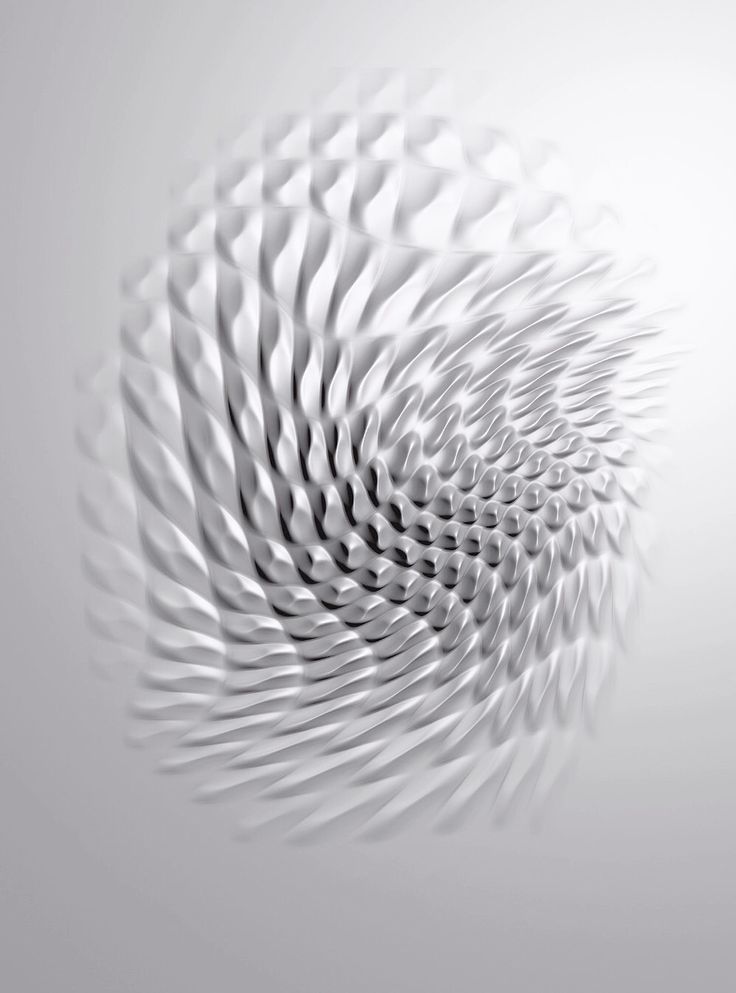 There are different scripts for different control firmware. I'm using Marlin firmware and the 'Pause at height' script works well for me.
Then it remains
- to select the moment for the pause - at what height from the table or at the beginning of which layer, by number, the pause will occur,
- select the nozzle parking place for convenient waiting for the filament change,
- how much filament to pull out of the nozzle and at what speed .
- how much plastic to extrude I leave 0,
- I set the waiting temperature to 25C so that I can leave the printer waiting for as long as I like.
- Redo Layers allows you to repeat, for example, 1 layer for a better connection between different colors.
During printing, the printer will execute the commands specified in the script and wait for the user to press the control button. after that, it will start heating the nozzle to operating temperature and continue printing. While the nozzle is heating, it is necessary to have time to manually push through the remnants of the previous color.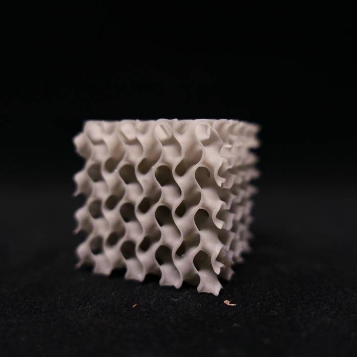 The script allows you to push through the color automatically, but will require close attention to yourself so as not to miss the moment of pause. Otherwise, you leave the hot nozzle for a long time and the plastic may degrade inside the nozzle. This will result in a broken seal and an unplanned clean hot end.
And on this rosy note, I conclude the first part of the course of lectures.
The second half of the lecture will be devoted to post-processing techniques, an overview of the principles of modeling for 3D printing and related technologies.
See you again.
Texturing 3D models to increase strength.
Technical
Follow author
Follow
Don't want
35
“Raise3D's IdeaMaker 3D Printing Slicer recently implemented a new feature in the latest version 4.1.1 called texturing. It allows you to “wrap” a grayscale image around your part, and depending on the gray value of the pattern (template) during printing, the shape of the outer contours changes .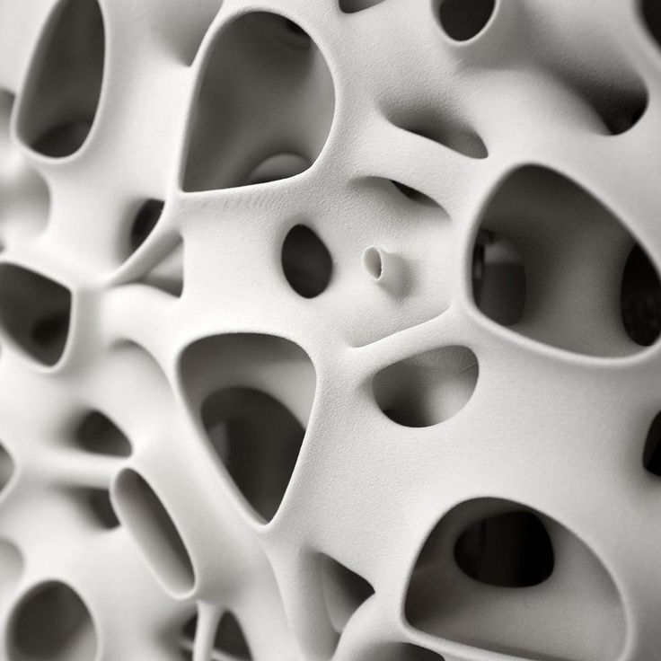 .. "
.. "
*This function can be used to decorate the surface of a printed object, but what about durability?
“To make the thin steel surface more durable, manufacturers add 'stiffening ribs' to their parts, thereby increasing the resistance to deforming loads.
Look at this piece of paper. In its original form, it can barely support its own weight, but if you add a few folds, the same sheet becomes an order of magnitude stiffer and stronger ... "
“But back to 3D printing. We are primarily interested in the "vase mode" - printing a part in one contour (without filling) in a continuous spiral.
In this case, with simple shapes, the parts are very fragile.
And one more thing: you may have already seen that simple forms also tend to deform a lot during printing. The larger the printed object, the more pronounced this effect.
The material also affects the amount of deformation. You can see this least of all with PLA, because it doesn't "shrink" much, but once you use PETG or ABS, this effect is in full effect: flat as well as curved surfaces are heavily deformed.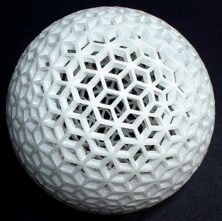 Why is this happening?"
“Here's the thing: In 3D printing, we print in layers. Each new layer is superimposed hot on the previous one and while it cools, it shrinks and “pulls” the already cooled previous one along with it ...»
**For the same reason, delamination of ABS parts occurs. To solve this problem, you need a printer with an active thermal chamber (heated), which reduces internal stresses during printing.
“ideaMaker's texturing engine helps us make thin-walled parts more rigid and printable. Texturing allows us to add relief to our parts without having to manually create it in CAD. This option adds the minimum amount of material because the "outline" lengthens a little, but increases the rigidity in the way that we need ...
…If you've never used IdeaMaker, you can download it for free. Once installed, simply browse the online library to see if there is a profile for your printer. If not, then just look for something similar, and then adjust the settings.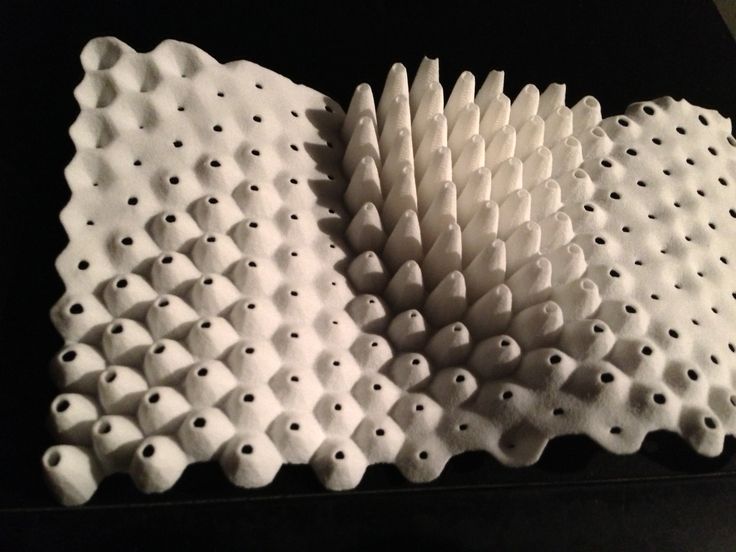 It's just as easy to import a part and select a texture icon: add a pattern by selecting one from the library or upload your own. Just make sure you can make a "seamless" texture out of it."
“To create a texture, just google ‘pattern’ and you will find many that may suit you… In the menu you can select the blend mode you want to use for your part to project the texture and also scale and rotate the pattern according to your needs."
“…Not every texture will stiffen your part! Depending on the type and orientation of the pattern, it can either increase or decrease! This is a whole science (Bead pattern design for lightweight structures)…
“…Adding a nice hexagonal pattern on the outside of the cylinder (“pipe”) already strengthens it a little, but if you add the optimal horizontal pattern, it becomes much stiffer! You may not find the perfect pattern right away, but the ease of use of the texture module will help you try out different options very quickly.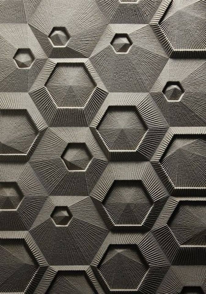 ”
”
Source: "Texturing 3d prints in ideamaker for strength"
Download IdeaMaker: Download IdeaMaker
Texturing Guide: Texturing Guide
*, **, *** - translator's comments.
More interesting articles
12
Subscribe to the author
Subscribe
Don't want
KDPV is not mine, stolen from some site, of which many have been rummaged.
It all started...
Read more
5
Subscribe to the author
Subscribe
Don't want
Hello everyone. Recently I found a new way for myself to get rid of the plug in the printer...
Read more
258
Subscribe to the author
Subscribe
Don't want
Snot.