3D printed geometry
Complex geometries are possible with 3D printing
Industrial 3D printing means that the manufacturing process no longer determines the complexity of a component, but rather the product’s desired functionality and design. Complex geometries, such as three-dimensional structures with undercuts or cavities, are typically impossible to manufacture with conventional technologies like milling, turning or casting, or are only possible at disproportionately high costs.
Now, any shape that can be constructed in a 3D CAD program can be produced with additive manufacturing technology. There are almost no restrictions – even when manufacturing hollow structures. This works because the material is only added where it needs to go. Additive manufacturing gives developers maximum geometric design freedom, and complexity only plays a minor role in the production costs. The costs can often even be significantly reduced due to lower material consumption.
EOS technology was a logical choice for us because we manufacture small series productions with complex shapes. We acquired the high-temperature system EOS P 800 at an early stage and were able to rapidly make progress in the development cycle of OsteoFab™ technology. EOS accompanied us throughout the entire process.
Scott DeFelice | President and CEO | OPM
Multiple structures in the same part
Thanks to 3D printing, the hip cup implant was significantly optimized. The artificial hip cup consists of solid sections that provide stability and porous elements on the surface. The differently sized pores help to anchor the implant firmly: Large pores are helpful for pressure transmission - smaller pores support the initial fixation. In this way, the complex surface structure simplifies osseointegration, or the growth between the living bone tissue and the surface of the implant.
Flexible structural adjustment possible
The full implant is manufactured in a single production step by the 3D printer and would be extremely difficult to make with conventional manufacturing methods.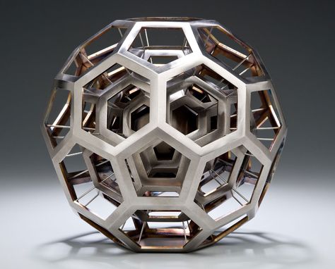 At the same time, the high flexibility of additive manufacturing enables the structure, surface roughness and pore size to be determined individually for each patient. Together with the Additive Minds Team at EOS and the established 3D metal printing system EOS M 290, Permedica succeeded in realizing a completely new product.
Evolutionary processes have created biological structures in great abundance and diversity: today, we know of more than 1 million species of animals and around 500,000 species of plants. These systems often have shapes and structures that are optimally adapted to their environment and are created with minimal use of materials and energy. The interdisciplinary research field of bionics aims to exploit this massive potential by adapting natural blueprints to technical applications.
This is where conventional manufacturing processes encounter their limits. By contrast, additive manufacturing achieves maximum design freedom. With our technology, you have the opportunity to build, discard, re-engineer and continuously optimize your prototypes during development.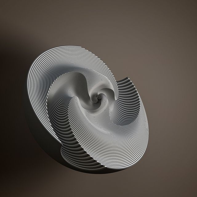 The tool-free production saves time and money - while offering enormous opportunities. As a result, there have been disruptive innovations in medicine, ergonomics and aviation, for example, especially in connection with aerodynamics.
Success Story Festo
Bionic Gripper
The additively manufactured Festo gripper DHDG is a bionic gripping device that can grip objects gently and flexibly but powerfully, and set them down safely. Its shape and function were inspired by nature. With the FORMIGA P 100 by EOS, the automation specialists Festo were able to produce the parts they needed quickly and cost-efficiently in small series production.
The results are impressive.
Thanks to the superior design freedom, the production can be flexibly guided by the design. By integration functionality into the part during production, Festo succeeded in significantly reducing the number of individual parts and the assembly cost. The resulting gripper is lightweight and durable.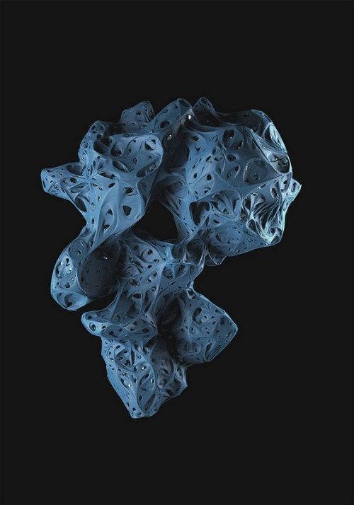 And even the price is right: Festo saved time and money with tool-free production.
Thinking in new ways is worth it: you can’t drill around corners, but you can easily print holes. The geometric freedom of design granted by industrial 3D printing opens new possibilities for designers. This requires know-how and a new approach to design.
We're here to help you take full advantage of additive manufacturing.
There are many upsides to 3D printing. EOS technology allows highly complex parts featuring functional integration and maximum product customization to be developed and manufactured quickly.
Geometric best 3D printer files・Cults
Spooky Seven-sided Flower Vase!!!
Free
Take Away Coffee Cup Clay Cutter - STL Digital File Download- 11 sizes and 2 Cutter Versions
€2.30
Potion Bottles!!!
Free
Cats decor
€3 -30% €2. 10
10
Deco Earring 2 Clay Cutter - Fan STL Digital File Download- 13 sizes and 2 Cutter Versions
€2.30
Deco Earring 1 Clay Cutter - Fan STL Digital File Download- 14 sizes and 2 Cutter Versions
€2.30
Flower 1 Clay Cutter - STL Digital File Download- 10 sizes and 2 Cutter Versions
€2.30
Flower 2 Clay Cutter - STL Digital File Download- 10 sizes and 2 Cutter Versions
€2.30
Shooting Moon Clay Cutter - Celestial STL Digital File Download- 12 sizes and 2 Cutter Versions
€2.30
Aztec Shape 1 Clay Cutter - STL Digital File Download- 10 sizes and 2 Cutter Versions
€2.30
Square Drop 2 Clay Cutter - Abstract STL Digital File Download- 12 sizes and 2 Cutter Versions
€2.30
Square Drop 1 Clay Cutter - Abstract STL Digital File Download- 12 sizes and 2 Cutter Versions
€2.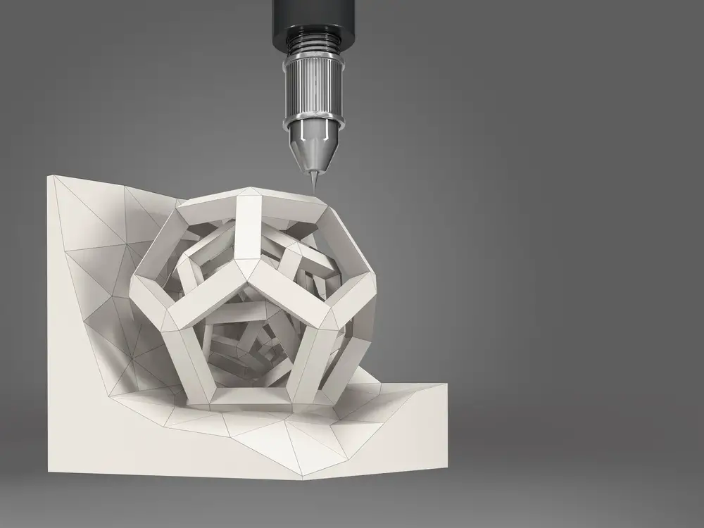 30
30
Bubble Drop 2 Clay Cutter - Abstract Ocean STL Digital File Download- 12 sizes and 2 Cutter Versions
€2.30
Bubble Drop 1 Clay Cutter - Abstract Ocean STL Digital File Download- 12 sizes and 2 Cutter Versions
€2.30
3D GEOMETRIC DIAMOND WALL PANEL
€9 -50% €4.50
german shepherd
€0.50
CAT AND MOON AND GEOMETRIC
€0.50
3D GEOMETRIC DIAMOND WALL PANEL
€9 -50% €4.50
Geometric wall art 4 pcs for bigger print, deer
Free
3D GEOMETRIC DIAMOND WALL PANEL
€9 -50% €4. 50
50
CAT ON BRANCH
€0.62
DOG carlino
€0.50
daenerys targaryen 3 dragon
€0.50
ELEPHANT
€0.50
Rudolph 1 Clay Cutter - Christmas STL Digital File Download- 8 sizes and 2 Cutter Versions
€2.30
Deer 1 Clay Cutter - STL Digital File Download- 8 sizes and 2 Cutter Versions
€2.30
Santa 2 Clay Cutter - STL Digital File Download- 8 sizes and 2 Cutter Versions
€2.30
Santa 1 Clay Cutter - STL Digital File Download- 8 sizes and 2 Cutter Versions
€2.30
DRAGON
€0.50
geometric mate selection Uruguay
€2.20
2D wall decoration cat at the window
€0.62
Wall decoration 2D cat in the arms
€0. 62
62
2D cat wall decoration
€0.62
2D wall decoration cat on moon mandala
€0.62
2D cat wall decoration x3
€0.62
Earring Combo 2 Clay Cutter - STL Digital File Download- 9 sizes and 2 Cutter Versions
€2.42
Earring Combo 1 Clay Cutter - STL Digital File Download- 9 sizes and 2 Cutter Versions
€2.42
Modern Earring 5 Combo Clay Cutter - STL Digital File Download- 12 sizes and 2 Cutter Versions
€2.65
Modern Earring 4 Combo Clay Cutter - STL Digital File Download- 12 sizes and 2 Cutter Versions
€2.65
Modern Earring 3 Combo Clay Cutter - STL Digital File Download- 12 sizes and 2 Cutter Versions
€2.65
Modern Earring 2 Combo Clay Cutter - STL Digital File Download- 12 sizes and 2 Cutter Versions
€2. 65
65
Modern Earring 1 Combo Clay Cutter - STL Digital File Download- 12 sizes and 2 Cutter Versions
€2.65
2 designs of Drop Frill Petal Clay Cutter - Flower STL Digital File Download- 10 sizes and 2 Cutter Versions
€4.15
Drop Frill Petal 2 Clay Cutter - Flower STL Digital File Download- 10 sizes and 2 Cutter Versions
€2.30
Drop Frill Petal 1 Clay Cutter - Flower STL Digital File Download- 10 sizes and 2 Cutter Versions
€2.30
Seashell 2 Clay Cutter - Mermaid STL Digital File Download- 10 sizes and 2 Cutter Versions
€2.30
Seashell 3 Clay Cutter - Mermaid STL Digital File Download- 9 sizes and 2 Cutter Versions
€2.30
3D GEOMETRIC WALL PANEL
€9 -50% €4.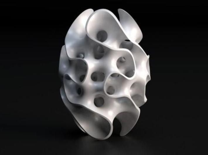 50
50
Geometry, not everything is so simple
Personal diaries
Subscribe to the author
Subscribe
Don't want
2
Geometry .... seemed like an exact science to me at school. Until I got a 3D printer.
print gurus and those whose printer prints 'out of the box' everything is exactly the size in size is not worth reading.
Prehistory. For about a year, with varying success, I have been mastering 3D printing. The printer (the first) is a pruche-like Chinese whale FLSUN, which, after minor modifications, began to give me quite acceptable print quality. In the beginning there was PLA plastic and, of course, a lot of marriage ... or these were just tests. When it came to modeling parts for which connections, joints, were subsequently planned, I encountered the phenomenon of a size difference in the size of internal holes. As a rule, the difference was up to 0.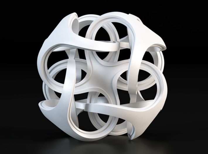 4 -0.6 mm (X and Y axes, of course, there were no such problems in Z, or insignificant on high parts), with the same external dimensions. After reading the information, asking for 3d thudey, I found out for myself that this is due both to errors in the mechanics of the printer, and to the phenomenon of plastic shrinkage. In general, I reconciled myself and manually made corrections for the difference during modeling, or made trial parts of the parts, measured them and, after correcting, put them into print.
By the way, the slicing was done either by Cure or in Simplify3d.... it didn't change anything. I settled on Cura for this printer, it's more convenient. On the second (because of Sailfish) I use Simplify3d.... it's more convenient there
BUT nothing lasts forever under the moon.
I switched from affordable pla to ABS, also tried PETG printing, the principle in building models was the same. Everything more or less worked out. Until the next reel of GREG PLA plastic, despite the fact that before that I had already printed three reels of a different color from this manufacturer.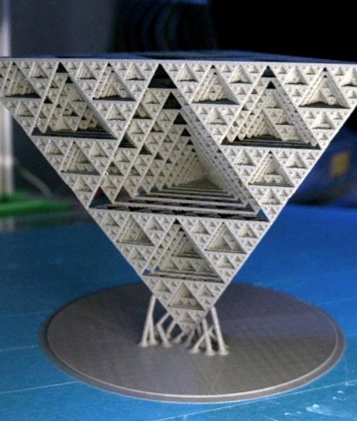 Generally blue. Strange properties, not very similar to PLA - less brittle, easier to cut with a clerical knife .... and does not require correction of parts - an error of 0.1 - 0.05 mm on internal dimensions (up to 0.6 mm before. After the test, printing the necessary details, put the coil on NZ, no laughing0003
Returned to 'normal'.
I decided to stir up a more complex project with a large number of printed parts, I made a project in SolidWorks. And since pairing with tolerances ... or whatever it is called ..... I can’t do it. Therefore, all the details were made in absolute dimensions. It came to printing ... and it turns out a lot of the details need to be edited. and then redraw. So the question arose .... is there a way to improve this? How to model details in the program, if you know that you will need to adjust the dimensions before printing. If she is alone, then this is not long, but if there are many of them? It is interesting to know how it copes (who has a similar problem).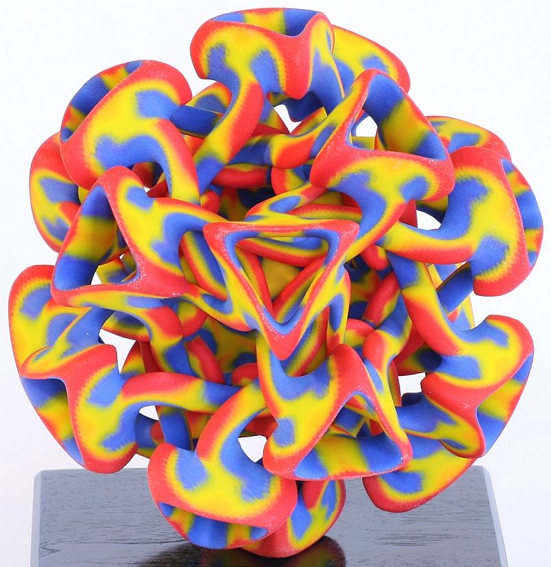
Having printed out a stand for a drill designed by mister Magomedov from PLA, I was pleased with the result. But there was no nylon on hand (enough). But I decided to try later. And the other day I decided to make a test part from a new project from nylon, more precisely from a trimmer fishing line. After tests with print parameters, I kicked out the first part, but there were several delaminations, either the temperature of the extruder, or the heat chamber was bad. In general, I slightly increased the printing temperature and added a casing during printing, removed the retract (it seems worth leaving, but minimal) .... and a good detail came out .... errors in the departure and table along the edges (until I picked up a suitable adhesive intermediary), but didn't get any splits. The part is strong - it didn’t break with hands and teeth))
And pretty yellow. Until I took the barbell in my hands (I made the correction as usual)
But the photo is visible
.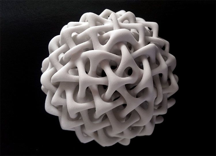 .... inserted at random.
in general - the error in most cases by 0.5 mm is easy to correct (according to external dimensions). But the detail (in the section of a right-angle, which was supposed to be put on a profile 25 mm al pipe) has a difference in internal dimensions of 1.2 mm. I didn't expect this.
What are the properties of plastic? I realize. that it is not intended for 3D printing, but ... I have a large coil. gotta use it somehow0003
Second printer without heated bed, I can't try it there
Follow author
Follow
Don't want
2
More interesting articles
vetrock
Loading
09/22/2022
896
7
Subscribe to author
Subscribe
Don't want to
In Van Helsing, Gabriel Van Helsing (Hugh Jackman) uses two custom revolvers. ..
..
Read more
vetrock
Loading
09/23/2022
503
2
Follow author
Follow
Don't want
In Batman v Superman: Dawn of Justice, Bruce Wayne (Ben Affleck) uses...
Read more
55
Follow author
Follow
I don't want to
On the net now you can find not just a lot, but a lot of descriptions of different kinematics, analysis of strengths ...
Read more
Fundamentals of 3D modeling for 3D printing / Habr KolianM
Working with 3D graphics *Prototyping *DIY or DIY 3D printers or milling. This is due to the technical features of the 3D printer, from which you need to either squeeze the maximum benefit, or adjust to the disadvantages of printing.
As a caveat, I note that these recommendations relate mainly to the FDM (FFF) 3D printing method, in which a plastic rod is heated by a moving extruder that forms the part layer by layer.
3D model development starts with a sketch. It can be a drawing on paper, a material prototype, a mental image, etc. What is important to pay attention to when creating such a sketch and the model itself, we will analyze in detail.
Part strength
Here and further down the text there are several sub-points that must be taken into account at the same time, kept in mind from the very beginning.
- Be aware of the layering or anisotropy of the material: it is much easier to break a part in layers than across. This must be taken into account in advance, given the location of the 3D model on the 3D printer table.
- Add fillets. The leg of the stool and the tabletop at the junction should have a rounded corner. At the same time, the larger the radius of curvature, the stronger the leg will be fixed on the table top. Similarly for various body parts. Modeling a box All right angles are rounded. It doesn't matter what plane they are in. Even where a right angle is needed, we make a radius of 0.5 mm. The printer will pass through such a section more easily than an unrounded one, there will be no impact from a sharp stop of the extruder, the part will not sway, and other pluses.
- Wall thickness and filling. The maximum strength at 100% infill is a fact, but if you need to lighten the part or save plastic, you can make a much larger wall thickness in the print settings, while setting the infill much lower. This works with parts that have holes for fasteners. When creating machine code for a printer, absolutely all the outer walls are thick, so the fastener will be surrounded by a reliable thick layer of plastic of your part.
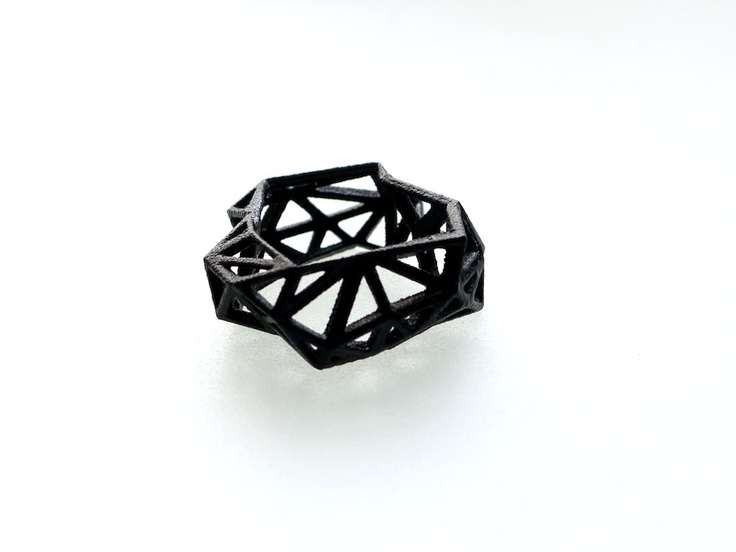
- Support. This element affects the strength in that the layers supported by the support are not always ideal in structure. This can be solved by increasing the wall thickness, filling, but it is better not to do support at all. Support is added by the slicer depending on the angle between the part wall and the table plane. Often the default is 60 degrees, sometimes 45. This setting is selected experimentally for each 3D printer. You can check this with the help of special test parts. For example, https://www.thingiverse.com/thing:2806295 - do not forget to turn off support to check the real quality of 3D printing in its absence. For example, you need to print a T-piece for tubes. Cast products are made in a T-shape. 3D printing makes the product L or even Λ-shaped. In the second case, support can even be avoided, and the part will be stronger due to the layers located at an angle of 45 degrees to the tubes. We, in the workshop, set up slicers for each machine and ask the client about the strength requirements, and, depending on this, choose a 3D printer to print.
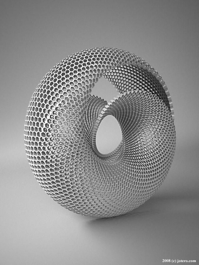
Geometric restrictions
- The wall thickness is limited from below by the size of the 3D printer nozzle. Its diameter is constant and in the vast majority of cases it is 0.4 mm. Smaller thickness - long 3D printing for most parts. The larger the nozzle, the bonds between the layers are less strong, the steps between the layers are more visible. And in general, the wall thickness should be a multiple of 0.4 mm, then the 3D printer will be able to accurately make the wall in two passes (0.8 mm), in 3 passes (1.2 mm), etc. Other thicknesses will cause the 3D printer to leave a gap or overflow, which negatively affects the strength and appearance of the printed part.
- 3D printing of thin cylinders and "needles". For 3D printing of such products, special 3D printer settings are needed: low 3D printing speed, allow time for cooling, otherwise such a structure will bend. Vertically standing thin elements are best avoided at all costs.
 Even if they are printed, they will be very fragile. It makes sense to leave them only for decorative purposes, but you must be prepared that their quality will be worse than the quality of other elements of the 3D part.
- 3D printed holes. I note that if the hole is straight and through, then it can be drilled, if it is curved and requires support, then it may turn out that it will be impossible to get support.
- When 3D modeling, it is important to consider the overall dimensions of the 3D printer. We use convenient 3D printers, table 250x250 mm, diagonal 353 mm. This is where you need to enter the dimensions, if possible. Otherwise, you need to order either an industrial 3D printer with a large print area, or use gluing, but assembly is better, so the assembly process will be controlled by the developer, and not by the 3D printing master.
- Large footprint may cause edges to peel off the table. We use special glue, but this does not always help.
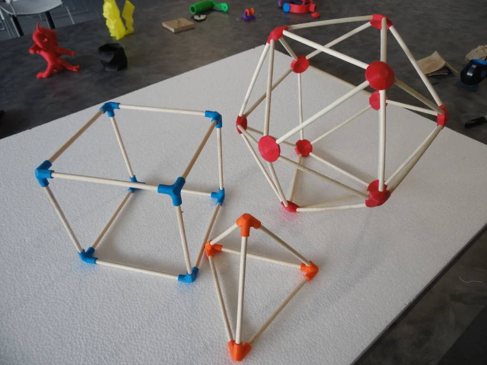 We are periodically approached with a complaint about colleagues in the shop that for them such “minor” defects as a folded edge are not a reason to restart 3D printing, take it as it is. But an engineer who 3D models a part can take this into account in his work and make either assemblies or thin-walled flat 3D parts that “do not have enough strength” to compress the outer contour and, as a result, raise the edge.
- Tall and thin "towers" may not work well due to vibrations that occur when the 3D printer is running closer to the top, and layer shifts are also possible.
Dimensional stability, accuracy
- Precise 3D printing is quite rare. I don’t want to speak in engineering terms here, but the likelihood that a complex composite structure will assemble the first time is very low. Here, rather, you need to take into account the fact that you can then mechanically refine the details.
- Holes for fasteners are best done with a margin of 0.
 5 mm in diameter. This will not reduce strength, the fasteners will also not dangle due to tightening forces, but if you do it without a margin, you will definitely have to drill it out. Reducing the size of a large shaft, >10mm sandpaper is much easier than making a hole, which requires a huge drill that cuts into the plastic walls and breaks the part, or gets stuck in it. It is also important to consider that when drilling, the plastic melts and the drill can melt into it so that it cannot be removed. There have been cases.
- Heat shrinkage is not always compensated, more precisely, it is very difficult to catch it, it is not the same in different directions, so it is extremely difficult to take it into account. It's easier to print a test version, and then make adjustments.
When looks matter
- Think about how the craftsman will orient the part on the 3D printer table. 3D printing proceeds in layers, which is clearly manifested when printing surfaces that are at a small angle from the horizontal of the table.
 Skinning will be long and painful, because you will have to cut this "ladder" to the deepest depressions of the "steps". It is better to place such surfaces either horizontally, for example, put on a table, or increase the angle. In some cases, even adding support that spoils the wrong side of the wrong side saves time and effort on post-processing.
- Support. First, the surface it supports has significantly more defects than without it. Secondly, thin and high support is weak, wobbly, which leads to the fact that the supporting part may have serious defects, or not work at all.
- First layer quality improvement. You need to add a bevel. Even where a sharp corner is not needed, I recommend adding a chamfer of 0.5 mm. It will not be clearly visible, but the edge will be neat.
What you need to know in order not to make a mistake when ordering 3D printing
If appearance is important
- Placement of the part on the table.
 Remember about anisotropy.
- Wall thickness and filling. What you can run into here: the filling is 20% cells, which are either visible through a thin outer wall, or the filling slightly tightens the outer wall during shrinkage, but at the same time it is visually easy to determine that there is support inside. Here, first of all, an increase in the thickness of the outer wall, or an increase in the filling density, helps. Please take this into account when ordering.
Postprocessing
The elimination of stepping is achieved by mechanical and chemical methods. It is possible to use putty. Acrylic paint available. If the part has a complex color structure, then we use the ProJet 4500 printer, which works on a different technology. He glues the powder particles together with colored ink glue. It turns out well.
Morality
In conclusion, I would like to note that these recommendations and the accumulated experience will make it possible to produce parts by 3D printing, which in their properties will not be inferior to cast ones, which makes it possible to save significant funds in the presence of a customized printer and small production volumes.


