Xyz 3d scanner driver
XYZ hand held 3d scanner troubleshooting - Scanning - Talk Manufacturing
Tim_Jason_Sparr
#1
so i just got my scanner a new imac and run and installed parallels and have windows 10 running smoothly on my mac … installed the intel real sense sdk as part of the xyz packaged software and i keep getting a error 5041 device not found , please try again message , i have updated the software and controlled all drive updates for the usb 3 ports , its still not working , can any one help …
1 Like
Xeno
#2
Did you assign the right USB port to Parallels ?,
when you plug in your device, Parallels should ask where you want the USB device connected to, Win or OSX.
Tim_Jason_Sparr
#3
yes i did … im just wondering if perhaps the scanner has an internal fault as the button on the scanner lights up … i shall look into trying the scanner on a up to date pc ( local pc outlet ) … if it gives the same error perhaps its a hardware problem … will let hou know … Thanks for you help …
micahwelner
#4
@Tim_Jason_Sparr did you ever figure this out! i was about to purchase the XYZ before i realized it wasn’t mac friendly. then i remember parallels which i already had a copy of. did you ever get it to work through parallels? hope so! let me know thanks happy holidays
Tim_Jason_Sparr
#5
I haven’t managed yet to run it through parallels .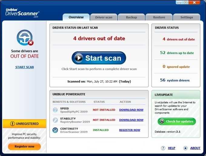 I went to a PC shop and they had it up and running on a new pc with the latest intel chip . I have a new iMac ( literally a month old) and the technician at the pc shop thought there may be an issue with the type of intel chipset that mac uses . its all down to the intel real sense camera that the device uses and perhaps also usb power issues . It may be a graphics card issue too . For now if you haven’t a pc I’m not sure if its going to work . Which is a shame , would be nice if xyz-printing had a wiki or its own help page on this considering the 3d printer (junior) runs ok on my iMac , suppose its about licensing with intel or microsoft or something … anyone else manage to solve this …please help out as i have a scanner doing nothing … would have been nice to get it up and running for the holidays …
pomusa
#6
I bought this item recently and it was missing the SD card. I was wondering if you still have the driver for Windows 10?
thanks
Boon
Tim_Jason_Sparr
#7
i will take a look … its now still in its box … will try to get it running this weekend
PAK5000
#8
I get the same error on a windows 10 pc. and there was no SD card in the box. and i can’t find the driver on their site. also, on the first machine i installed this on, it never prompted for a driver. the scan quality was just very low and compared to the how to videos, it took me a lot longer to get a scan. then the scan button would not enable. the button on the scanner lit up but did nothing. that was in xyz handy. i tried 3d sense. as soon as i hit the scan button the app crashed. so tech support said try another pc. xyzhandy wants a mystery driver and 3dsense does not detect a scanner. i think the scanner went bad and am working with them to get a replacement.
updating all the windows drivers, the intel realsense and graphic card drivers, did get it working for a short time on the original pc. but there was no SD card. and the apps never prompted for a driver. i think it is just a bad scanner they need to replace.
▷ xyz 3d scanner software 【 STLFinder 】
Teddy — XYZ 3D Scanner — XYZ Software
sketchfab
Part of my XYZprinting 3D Scanner Review. ...Scanned using the XYZscan software.
Patrick — XYZ 3D Scanner — XYZ Software
sketchfab
Part of my XYZprinting 3D Scanner Review. ...Scanned using the XYZscan software.
Sneaker High — XYZ 3D Scanner — Sense Software
sketchfab
Part of my XYZprinting 3D Scanner Review. ...Scanned using 3D System’s Sense for RealSense Software.
Bear Low — XYZ 3D Scanner — Sense Software
sketchfab
Part of my XYZprinting 3D Scanner Review. ...Scanned using 3D System’s Sense for RealSense Software.
Patrick High — XYZ 3D Scanner — Sense Software
sketchfab
Part of my XYZprinting 3D Scanner Review. ...Scanned using 3D System’s Sense for RealSense Software.
Teddy — XYZ 3D Scanner — Sense Software
sketchfab
Part of my XYZprinting 3D Scanner Review. ...Scanned using 3D System’s Sense for RealSense Software.
Patrick Low — XYZ 3D Scanner — Sense Software
sketchfab
Part of my XYZprinting 3D Scanner Review. ...Scanned using 3D System’s Sense for RealSense Software.
Sneaker Low — XYZ 3D Scanner — Sense Software
sketchfab
Part of my XYZprinting 3D Scanner Review. ...Scanned using 3D System’s Sense for RealSense Software.
Bear Cropped — XYZ 3D Scanner — Sense Software
sketchfab
Part of my XYZprinting 3D Scanner Review. ...Scanned using 3D System’s Sense for RealSense Software.
Patrick Medium — XYZ 3D Scanner — Sense Software
sketchfab
Part of my XYZprinting 3D Scanner Review. ...Scanned using 3D System’s Sense for RealSense Software.
XYZ 3D Hand Scanner Base
thingiverse
This is a holder/base for a XYZ 3D hand Scanner. It works as a holder when the 3D scanner is not in use but also allows for vertical scanning. It can be mounted to a tripod for vertical or horizontal scanning (must supply a 1/4-20 nut). There is a...
XYZ 3D Hand Scanner TRIPOD SUPPORT
thingiverse
XYZ 3D Hand Scanner tripod SUPPORT easier to use Somme application form https://appshowcase.intel.com/en-us/realsense
Teddy — XYZ 3D Scanner — RealSense 2016 R2 SDK
sketchfab
Part of my XYZprinting 3D Scanner Review. ...Scanned using the 3D Scanning sample app of the Intel RealSense SDK 2016 R2.
Patrick — XYZ 3D Scanner — RealSense 2016 R2 SDK
sketchfab
Part of my XYZprinting 3D Scanner Review. ...Scanned using the 3D Scanning sample app of the Intel RealSense SDK 2016 R2.
Sub 30$ 3D laser scanner Open harware/software project
thingiverse
UPDATE I’m proud to announce you the release of the open source Software for the “cheapest 3d scanner on earth” the 30$ DIY Sardauscan. The software Is written in C# and allow you to compose your Scan task by drag and drop. Recommended Process...
Sub 30$ 3D laser scanner Open harware/software project
prusaprinters
just 2 free usb port on your pc : one for the webcam the other for the rest. UPDATE I’m proud to announce you the release of the open source Software for the “cheapest 3d scanner on earth” the 30$ DIY Sardauscan. The software Is written in C# and...
Print Your Own 3D Scanner Kit (for IntriCAD Triangle software)
cults3d
Been working on this for a few weeks now, trying to build an easily assembled desktop 3D scanning kit to go with IntriCAD Triangle software... The idea was to create a casing that not only houses the turntable and the circuit boards that go with it,...
Print Your Own 3D Scanner Kit (for IntriCAD Triangle software)
thingiverse
Been working on this for a few weeks now, trying to build an easily assembled desktop 3D scanning kit to go with IntriCAD Triangle software. .. The idea was to create a casing that not only houses the turntable and the circuit boards that go with it,...
Coffee cup obteined using Ciclop 3D scanner and printed using XYZ Da Vinci 1.0
thingiverse
This coffee cup is obteined from 3d scanning using Ciclop. Processed using Meshlab, Meshmixer, netfabb and Cloudcompare. ... Instructions print using support and raft
Shapespeare's Infinite Resolution 3D Scanner - Printed Parts and Software Remix
thingiverse
cohost of [3D Printing Today Podcast](http://threedprintingtoday. com/), created an Arduino driven photo capture system for photogrammetry and published an...
Shapespeare's Infinite Resolution 3D Scanner - Printed Parts and Software Remix
cults3d
cohost of 3D Printing Today Podcast, created an Arduino driven photo capture system for photogrammetry and published an Instructable on how to build your own. You can find all the information on building, wiring, parts, etc in the original post. If...
Shapespeare's Infinite Resolution 3D Scanner - Printed Parts and Software Remix
myminifactory
cohost of 3D Printing Today Podcast, created an Arduino driven photo capture system for photogrammetry and published an Instructable on how to build your own. You can find all the information on building, wiring, parts, etc in the original post. If...
scanner 3d
myminifactory
scanner 3d con telefono
3D Scanner
grabcad
First prototype of 3D scanner
3D_SCANNER
grabcad
A 3D Scanner model with distance sensor
3D Scanner
grabcad
3d scanner based on intel realsense d435 camera
3D Scanner
grabcad
3D Scanner Concept. ...add me: twitter: @martinhajsinger linkedin: @martinhajsinger https://hajsingermartin.wixsite.com/home
3D SCANNER
thingiverse
some parts can be printed in large parts can be printed grabcad link to drop down https://grabcad.com/library/3d-scanner-14
3D Scanner
grabcad
It is a 3D scanner that is designed for Graphic Designing and Medical Purposes. ...It is a group project done by myself, Brice Veyna, Mohammad and Abdullah Alqahtani
3D Scanner
thingiverse
This project has been inspired by this project:http://www. instructables.com/id/Lets-cook-3D-scanner-based-on-Arduino-and-Proces/?ALLSTEPS Since I have a 3D Printer, I have made my own design for the turn table, the laser and camera holder. See the...
Home / Useful / Hyde for setting up 3D printer mechanics
04.05.2021
Content
-
- What includes mechanics
- Defects mechanical failure
- How to save settings
- Setup instructions
- Belts
- Motor current
- Motor steps
- Acceleration
- Jerk
- Speed
- Check settings
The quality of the printed models directly depends on the mechanics of the printer, namely on its correct settings. Any elements of the printer wear out over time, so the printer must be set up at least once every 5-6 kg of printed filament. With the help of the short instructions described in this guide, you can quickly and easily set up the mechanics of your printer: belt tension, motor current, motor steps, acceleration, jerk and speed.
Mechanics includes
3D printers of any design always contain the same things: Axes and rails along which the elements of the printer move and motors with belts that set these elements in motion. In a classic printer design, there are at least 3 motors (one for each axis), 3 rails (one for each axis) and an electronics board that controls the motors. The latter can hardly be called part of the mechanics, but since it controls the engines, it also indirectly affects the quality of the model.
Printing defects due to mechanical problems
Before changing anything in the printer, you need to decide what exactly needs to be configured. Often defects are visible visually. Our blog has an article about most printing defects, which details the reasons for their occurrence. The following is a list of defects and what element of mechanics they are associated with:
-
Layer shifting - Belts, Motor current, Guides
-
Ringing - Guides, Speed
-
Incorrect model geometry - Guides, Motor steps, belts
As you can see, all the above problems do not interfere with the printing process itself, but the result leaves much to be desired. Sometimes mechanical errors can completely stop the printer from working. Therefore, it is better not to take the situation to extremes and, if any problems arise, immediately start checking and configuring the 3D printer.
How to save settings
To fix some defects, you need to change the printer software settings. Therefore, before adjusting the mechanics, it is necessary to understand how to properly store the settings inside the printer. There are 3 ways to do this:
All settings are located in the corresponding menu of the printer
Depending on your firmware, this manual will indicate code sections for MARLIN firmware in the configuration.h file
We first enter the parameters into the printer and then store them in EEPROM - the internal memory of the microcontroller. Or paste all the necessary settings at the beginning of GCODE. To learn how to do this, read our article on working with GCODE and creating macros.
To save to EEPROM, you need to send the printer a command to change some value (which can also be inserted into the initial GCODE), and then send the M500 command (save the current settings to permanent memory). The EEPROM function must be enabled in the firmware, for this you need to remove two slashes in the line:
//#define EEPROM_SETTINGS
Whichever option you choose, you should be careful when using any commands. You will not be able to harm the printer in any way when changing the settings, but if you make a mistake, you will have to look for the cause of possible further problems for a long time.
Setting Instructions
Now you can start setting up the printer itself. If you decide to set several parameters at once, then it is better to use the order of adjustments as in the article, since some of the settings are related to each other and if you use the wrong order, adjusting one element of the mechanics will override the settings of another element. For example, you should not adjust the motor steps before tightening the belts, as changing the length of the belts will change the "true" steps per millimeter of the motors. Also, before setting up, you must make sure that there are no backlashes in the printer frame, tighten all belts.
Belts
The first thing to start setting up the printer is the belts. They directly affect the geometry of the model and, when pulled too much, they cause a lot of problems: displacement of layers, changes in geometry, ripples. First you need to make sure the belt is intact. To do this, look at the entire belt, especially the areas where the belts bend. If the belt has outlived its usefulness, then you can see a section of the belt where the distance between the teeth has greatly increased and a metal wire (cord) is visible between them. This means that it's time to completely change the belt.
Broken belt with broken cords
If the belt is intact or you have already replaced it, then you can proceed to the next step. Depending on the design of your printer, you need to move the roller through which the belt passes. The tension should be such that the carriage or table moves effortlessly, but at the same time, when moving quickly, the belt should not slip the teeth on the motor gear. Adjust the tension of the belts on each axis of the printer using this method.
Tip: if your printer came with a belt tensioner in the form of a spring attached to the belt itself, remove it. Due to the flexibility of this tensioner, printing defects will occur, such as protruding corners on the model. It is better to adjust the belt without using this tensioner.
Belt tensioner
Current motors
As we know from the school physics course, the power of the engine depends on the voltage and current strength. Since the voltage on all printer electronics is the same everywhere, the only thing that can be changed is the current on the motor. More precisely, it should be said the maximum current that the driver will supply to the motors. To change this limit, you need to climb inside the case and find the printer board. On it you will see the printer driver. We are interested in a small potentiometer on the driver itself (in the picture below it is indicated as a tuning resistor).
Example of potentiometer location on driver
For adjustment, you will need a voltmeter and a small Phillips or flathead screwdriver. Before proceeding further, it is necessary to calculate the maximum current supplied to the motors. Different formulas are used for different drivers, the most popular ones will be listed in the table below:
| Driver name | Formula | Explanations |
| A4988 | Vref = Imax * 1.25 for R100 | To understand which formula to use, you need to find a resistor with the signature R100 or R050 on the driver. They are located next to the driver chip. |
| DRV8825 | Vref = Imax / 2 | |
| LV8729 | Vref = Imax / 2 | |
| TMC2208 TMC2100 TMC2130 | Vref = Imax * 1. | One formula for all drivers |
The value of the maximum current (Imax) depends on the motor controlled by the driver. This can be found in the engine specification or on the sticker on it. The following are the currents for the most popular motor models:
17HS4401 - current 1.7 A
17HS8401 - current 1.8 A
17HS4402 - current 1.3 A
Substituting the value into the formula, we get the Vref value for the maximum current supplied to the motor. But at this value, the engine will get very hot, so the resulting Vref value must be multiplied by 0.7. For example, for a motor with a maximum current of 1.5 A and a TMC 2208 driver:
Vref=1.5*1.41*0.7=1.48V
Now the resulting value can be used when configuring on the printer itself. To do this, disconnect the wires going to the motors, turn on the printer and place one voltmeter probe in the center of the trimmer, and the second probe to the negative terminal on the power supply (you can also use the negative terminal on the printer board and the contact on the driver, labeled as GND). You will see some value on the voltmeter screen. Turn the trimmer clockwise to decrease the Vref value and counterclockwise to increase it.
Attention: you should not specify a Vref value higher than the maximum calculated for your engine! Otherwise, the engine will soon break down!
Once you have adjusted the value on the drivers, you can turn off the power to the printer, connect the motor wires, and put the case back together. This completes the driver setup.
Motor steps
When setting up motor steps, you will need a ruler. For convenience, you can use the program Repetier-Host. The adjustment for each of the three axes occurs according to the same algorithm:
-
Set the caret to zero coordinates (Autohome or G28)
-
Move the carriage some distance
-
We measure how far the carriage has traveled
-
We calculate the correct number of steps per millimeter using the formula:
True steps per millimeter = current steps per millimeter * reported distance / distance traveled
For example, if the printer was set to 100 steps/mm, we tell the printer to move 80mm and the printer travels 87. 5mm. Then the correct steps per millimeter would be 100 * 80 / 87.5 = 91.42 steps/mm. For the convenience of measurements, you can fix a ruler on the table, and a thin object, such as a needle or pin, on the carriage. Then it will be possible to accurately measure the distance traveled. The extruder uses a partially different algorithm to measure distance:
-
Inserting plastic into the extruder
-
Cut it right at the outlet
-
We give the printer a command to stretch the plastic a certain distance (at least 100 millimeters)
-
Cutting plastic again
-
We measure the length of the resulting piece of plastic
-
We use the formula from the previous algorithm
Next, the settings data must be inserted into the firmware in the line:
#define DEFAULT_AXIS_STEPS_PER_UNIT {X,Y,Z,E0}
X,Y,Z and E0 should be replaced by the steps per millimeter for each of the axes, respectively. Otherwise, you need to insert this line into the initial GCODE:
M92 Ennn Xnnn Ynnn Znnn
Instead of nnn in each of the parameters, you must substitute the steps per millimeter for each axis. If you want to adjust the steps only for not all axes, then you can remove unnecessary parameters.
Acceleration
This parameter is responsible for the rate of change of speed. That is, how fast the printer will change its speed. This affects the nature of the movement of the hot end relative to the table. If the acceleration is too small, then the printer will print slowly, if it is too large, then the outer surface of the model will have visual defects: fading waves will be visible near each of the corners, as in the picture below.
To set up acceleration, you need to follow simple steps:
-
Cut a model of a standard test cube with a wall thickness equal to one nozzle diameter, without filling and top layers, bottom 2-3 layers;
-
Open GCODE file in notepad;
-
Find the G28 command at the very beginning and insert the line data after it:
M201 X5000 Y5000
M204 P500 T500
-
Save the changes, print the model according to the received GCODE and note at what parameters P and T it was printed;
-
Open the same GCODE file and change the P and T values on the second line, adding 500 to each;
-
Repeat steps 4-5 at least 3 times;
As a result, you will get several test cubes, some of which will show waves at the corners. Choose the cube that is printed with the highest P and T parameters, but that no waves can be seen on it. The number in parameter P will be the desired acceleration value. To save this value, you need to find 2 lines in the firmware:
#define DEFAULT_MAX_ACCELERATION {X,Y,Z,E0}
#define DEFAULT_ACCELERATION {nnn}
Instead of X and Y, you should put an acceleration twice as high as found earlier. And instead of nnn, you need to put the acceleration value found earlier. Otherwise, you need to insert a line in the initial GCODE:
M204 Pnnn Tnnn
In the parameters P and T, you need to put the value of the found acceleration. After that, the acceleration setting can be considered complete.
Jerk
A jerk indicates the speed with which to start accelerating. It affects the model in a similar way as acceleration: it creates ripples around the corners of the model. But it also increases the protrusion of the corners if the jerk is too small. The jerk setting is also similar to the acceleration setting:
-
Cut a model of a standard test cube with a wall thickness equal to one nozzle diameter, without filling and top layers, bottom 2-3 layers.
-
Open GCODE file in notepad
-
Find the G28 command at the very beginning and insert the line data after it:
M205 X5 Y5
-
Save the changes, print the model according to the received GCODE and note at what X and Y parameters it was printed
-
Open the same GCODE file and change the X and Y values on the second line, adding 2 to each
-
Repeat steps 4-5 at least 3 times
As a result, you will get several cubes. Find a non-rippled cube printed at the highest X and Y settings. This will be the jerk value for your printer. To save them, you need to find the line in the firmware:
#define DEFAULT_XJERKnnn
#define DEFAULT_YJERKnnn
It is necessary to substitute the jerk values for the X and Y axes, respectively. Otherwise, you need to substitute the command in the starting GCODE:
M205
Instead of nnn, you need to substitute the jerk value found earlier. This completes the jerk setting.
Speed
In fact, there are many different speed parameters, the values \u200b\u200bof which vary greatly. Let's take a look at the main ones:
This parameter is responsible for moving the nozzle without extruding plastic. The value is in the range from 80 to 120 mm/s. Limited only by the maximum speed at which the motors can rotate. Does not affect the model
This speed is important because it indirectly affects the adhesion of the model to the table. Usually lies between 15 and 30 mm/s
-Print speed of inner walls
Usually set to about 60 mm/s, it only affects the strength of the model. Depends on the maximum amount of plastic that the extruder can push through the nozzle
-Speed of printing outer walls
Usually about half the printing speed of the inner walls (30 mm / s). It affects not only the strength of the model, but also the appearance: the lower this speed, the smoother the walls will be.
The standard value is 80 mm/s, it only affects the strength of the model
Usually set from 20 to 40 mm/s, the quality of the upper layer of the model depends on it: the lower the value, the smoother the cover.
All of the above parameters are selected experimentally. Usually there is a simple rule: higher speed - lower quality. Therefore, do not try to find the ideal value for all situations. It is better to find values for fast printing, quality printing, and an average that will be used for most models.
Check settings
The last step in setting any of the above parameters will be to check the result. If you have written parameters in firmware or saved them in EEPROM, you can use the M503 command. It will display all printer settings on the computer. To test the settings in practice, you can print several test models:
Classic Benchy
Simple calibration cube
Calibration cat
On each of the above models, defects will be clearly visible, if they still remain after the mechanics are adjusted.
#Useful
Expert in the field of additive and subtractive technologies, 3D equipment and CNC machines with over 10 years of experience.
Share
all materials
Do you have any questions?
Our experts will help you with the choice of 3D equipment or accessories, consult on any questions.
Inspection of large metal products: a 3D scanner will solve all problems
Geometry control
Implementation stories
Author: Sergey Dumilin
Author: Sergey Dumilin
Lincoln Electric Additive Solutions provides a full range of services for the manufacture and supply of metal products of large dimensions for various industries - electric power, oil and gas, transportation, aerospace, defense, and heavy industries.
Lincoln Electric was the first to master large-format 3D printing of prototypes, mass-produced parts, spare parts and tooling from steels, stainless steels, invars and nickel alloys. The additive manufacturing division of this multinational company knows first-hand how to make very large products - up to several meters in size and weighing up to several thousand kilograms.
Lincoln Electric - pioneers in advanced technology
Lincoln Electric has always prided itself on using the latest manufacturing methods to gain a competitive advantage. That is why the company was one of the first to develop and implement 3D printing technologies for the rapid production of high-quality large-sized parts, many of which have complex geometries.
In the additive manufacturing of metal objects, exact dimensions play a particularly important role. Because large, complex parts are being printed, traditional quality control tools (such as coordinate measuring machines or measuring arms) do not meet Lincoln Electric's requirements for speed and measurement versatility.
With the Creaform 3D Scanner, we get our products to market faster because we control part geometry faster.
Mark Douglass, Business Development Manager
Lincoln Electric Additive Solutions
For example, classical systems are not suitable for taking measurements directly on the shop floor. “We make very heavy and large parts,” says Mark Douglass, business development manager for Lincoln Electric Additive Solutions, “and it's important to us that the part doesn't have to be moved as much as possible. We knew that CMMs and measuring arms didn't meet this criteria and started looking for other options. The solution was 3D scanning.”
Want to see MetraSCAN 3D and other 3D equipment in action?
Leave a request for a demonstration of 3D equipment
Implementation of a 3D scanner in production
To quickly and accurately control the geometry and quality of printed metal products, Lincoln Electric Additive Solutions uses Creaform 3D measurement solutions. Designers and quality control professionals create 3D surface models of AM parts and compare them to the original CAD models.
Lincoln Electric additive manufacturing engineer Amanda Dodge notes, “Often times the parts we make have many unique elements, and it's important that each one is in the right place. The 3D scanner helps to capture all the complex elements we print and check if there are any errors.”
“Operators and engineers were enthusiastic about the new solution. Now we measure parts in just a few minutes,” Mark adds. “Creaform devices are portable and now we can bring them to the details, not the other way around.”
iQB Technologies experts recommend the article: Modernization of Atommash: how to reduce quality control time by 5 times
MetraSCAN 3D complements additive manufacturing of large parts
Along with the growth of Lincoln Electric Additive Solutions, the dimensions of the products manufactured have also grown. The company needed to find a way to quickly and accurately measure large parts without moving them. For this purpose, the Creaform MetraSCAN 3D 3D scanner was chosen - the fastest and most accurate portable 3D scanner for working in a production environment.
“MetraSCAN 3D is a great solution as it provides non-contact measurements. Position marks are not required. We can scan products and check their geometry and quality at any stage of production - even during 3D printing, when the temperature of the parts is very high, - Brad Barnhart, an additive manufacturing engineer, shares his impressions. “3D scanning helps measure parts much faster because technicians don’t have to wait for them to cool down.”
Amanda Dodge noted that parts do not need to be cleaned before 3D scanning, and this also saves a lot of time.
3D scanning is a powerful growth driver for your business
Mark Douglass believes that the use of Creaform 3D scanning systems has significantly contributed to the growth of the business.


 41
41 

