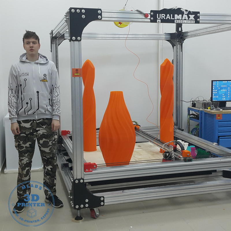
Switch hack 3d print
▷ switch rcm jig 3d models 【 STLFinder 】
Nintendo Switch RCM Jig_remix
thingiverse
This is a remix from [Nintendo Switch RCM Jig ](https://www.thingiverse.com/thing:4095790) from ShadowX. As there are two versions of the RCM jig for the Nintendo Switch : - wires spaced by 6.20mm apart - wires spaced by 2.54mm apart So I just added...
Nintendo Switch RCM Jig
thingiverse
This is another printable RCM jig.
What makes this file different than the other designs?
1) Its designed so that installing the wire is straightforward and very easy. There is no need for wire jigs since the part is the jig.
2) The...
Switch RCM Jig
thingiverse
After being frustrated with the preparation required to make a USB-based jig, I designed one from the ground up that minimizes stress on the Switch's connector and is a lot simpler to make. ...Simply force some 32 gauge wire into the slot and try to...
Switch RCM Jig case
thingiverse
I used to loss the Jig, so I made a box.
Switch RCM Jig Storage Cover
thingiverse
Before I got a 3D Printer, I had bought an "RCM Jig" at the recommendation of a Nintendo Switch CFW guide I followed. I checked the guide just now and can't seem to find the link, so maybe this particular seller is no longer in operation. But I've...
Hole-less Switch RCM Jig
thingiverse
My 3D printer couldn't print any of the RCM jigs with holes--It ends up squishing plastic down into where the holes should be-- So I modified this jig to hold a wire without holes. Just place the wire down into the two channels and tape it on the...
Small Nintendo Switch RCM Jig
thingiverse
... be bent up and down to push it up against the Joycon connector, without damaging the pads. It should be slightly springy.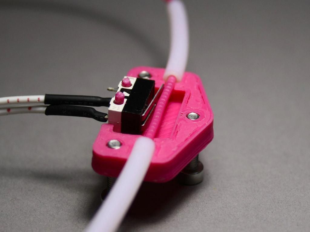 This model is a redesign/alteration/remix of the RCM Jig designed by yahnbaron. ...https://www.thingiverse.com/thing:2892320
Fusion Nintendo Switch RCM Jig
thingiverse
I liked the option of a keyring in [Sulya's](https://www.thingiverse.com/thing:2973594) RCM jig, but *loved* the design of [ShadoX's](https://www.thingiverse.com/thing:4095790) Jig. So I combined them! ____________________ ShadowX's Summary ...
NINTENDO SWITCH RCM JIG CAT5
thingiverse
Simplified version of jig
Yet Another Switch RCM Joycon Jig
prusaprinters
Hey here is another one of those joycon jig tools. I used cat5e wire removed from its protective coating and pushed into the slots.</p> <p>Print at 0.1mm layers or send it off to a high quality print service. ...Shapeways is great for little things like...
Yet Another Switch RCM Joycon Jig
thingiverse
Hey here is another one of those joycon jig tools. I used cat5e wire removed from its protective coating and pushed into the slots. Print at 0.1mm layers or send it off to a high quality print service. Shapeways is great for little things like...
Nintendo Switch RCM Jig SD card Game Cartridge Adapter
thingiverse
remixed to add sd card slot
Yet Another Switch RCM Joycon Jig with Keyring
thingiverse
Added a keyring opening so it can be attached to my switch case for safe keeping.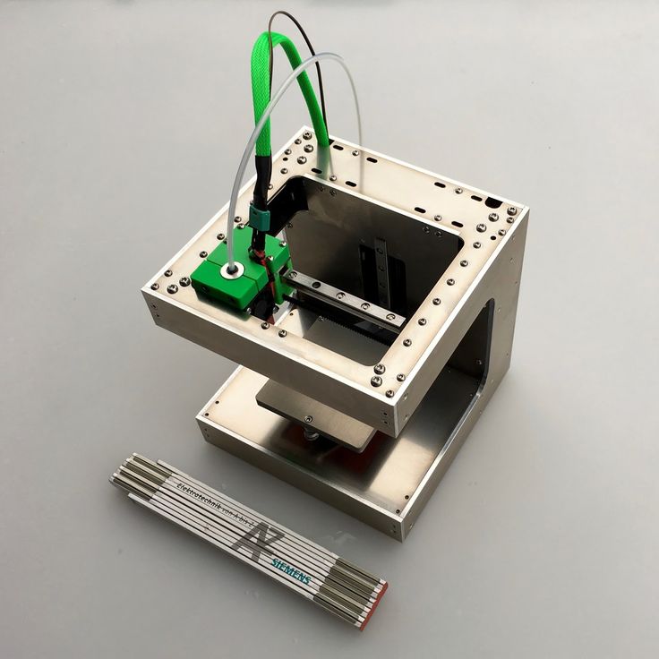
RCM Jig Switch HACK
cults3d
Jig for Nintendo Switch, facilitates the union of the pins to start the console in RCM mode and thus be able to inject pailoads. Don't gamble and don't damage your Switch! 0.4mm cable is recommended. ... Do not change size.
Jig RCM Switch
pinshape
Jig para Nintendo Switch, facilita la unión de los pines para encender la Nintendo en el modo RCM. Se recomienda usar cable de 0,4mm. ... No me hago responsable del mal uso del dispositivo.
Nintendo Switch Dual SDcard RCM+Jig Cartridge
thingiverse
I modified another JIG design using smaller holes, because all you need is a solid core CAT5e/CAT6 Ethernet cable or you could clip off the edges of a resistor.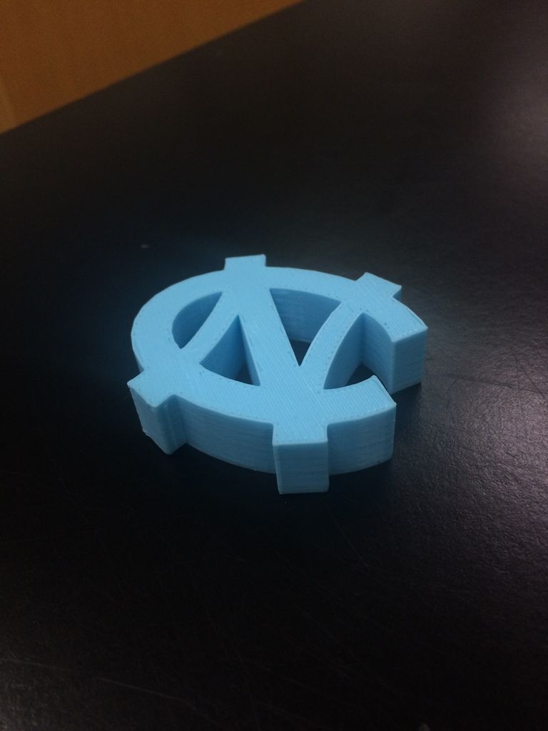 Don't forget to sand the edges of the metal so that you don't cause any stress on the...
Swiss Switch micro SD cards and RCM Jig Insert
thingiverse
This is an insert for the Swiss Army Style SD Holder This holder will hold two micro SD Cards, as well as my favorite RCM Jig (seen here: https://www.thingiverse.com/thing:2892320). the spaces to the left of the micro sd card are for labels. ...the...
RCM Jig and wire bending template for Nintendo Switch
thingiverse
Update 25th June: made the keyring hole a bit bigger, fixed issue with orientation: apparently the model was rotated a bit upon export to stl Description: Redesigned RCM jig, based on thing 2877484 but redesigned from scratch with following changes:. ..
..
RCM Jig and wire bending template for Nintendo Switch
prusaprinters
Update 25th June: made the keyring hole a bit bigger, fixed issue with orientation: apparently the model was rotated a bit upon export to stl Description: Redesigned RCM jig, based on thing 2877484 but redesigned from scratch with following changes: ...
RCM Jig Cartridge Adapter
thingiverse
This project aims to fit an entire RCM Jig into The Nintendo Switches cartrdige slot. It requires the use of a paperclip, which if the ends are left sharp, will most likely damage your Switch's Joy-Con rail.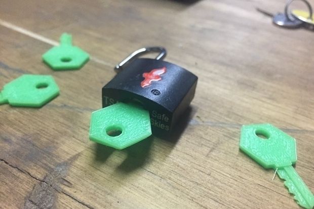 If the jig is too hard to slide into the...
Keychain MagnetHax Nintendo Switch (RCM)
thingiverse
Rather than having to remove the right joycon, put the JIG, switch to RCM, remove the JIG then put back the joycon, there is more to put the magnet directly behind the joycon and enjoy !!!!!! ... For more info : Magnethax switch English :...
RCM Jig with Cartridge holder for microSD card and jig
thingiverse
Tinkered with the wall thickness a little on both the cart and the height of the jig for a better fit Storage for a microSD is useful in case you often swap cards, for example if you run fusee on one and switchroot Android on another like myself.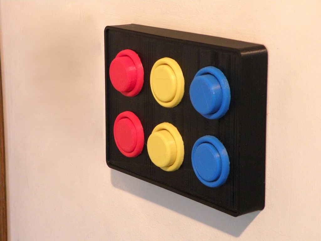 ..
..
RCM Jig with Internal Wire - M600 Pause Needed
thingiverse
Be careful when applying this jig to your switch, it will not be forgiving if you have allowed one of the wires to bend out of place or if you cut them too long. Of course, I assume no fault or responsibility if you use this wire in a way other...
Nintendo Switch Gamecard Jig
prusaprinters
This is a work in progress RCM Jig for the game card slot. The jig does work pretty well but still needs some adjustment. Right now you need to fiddle a little bit to make it work consistently.</p> <p>I will add the Fusion source files once I get it.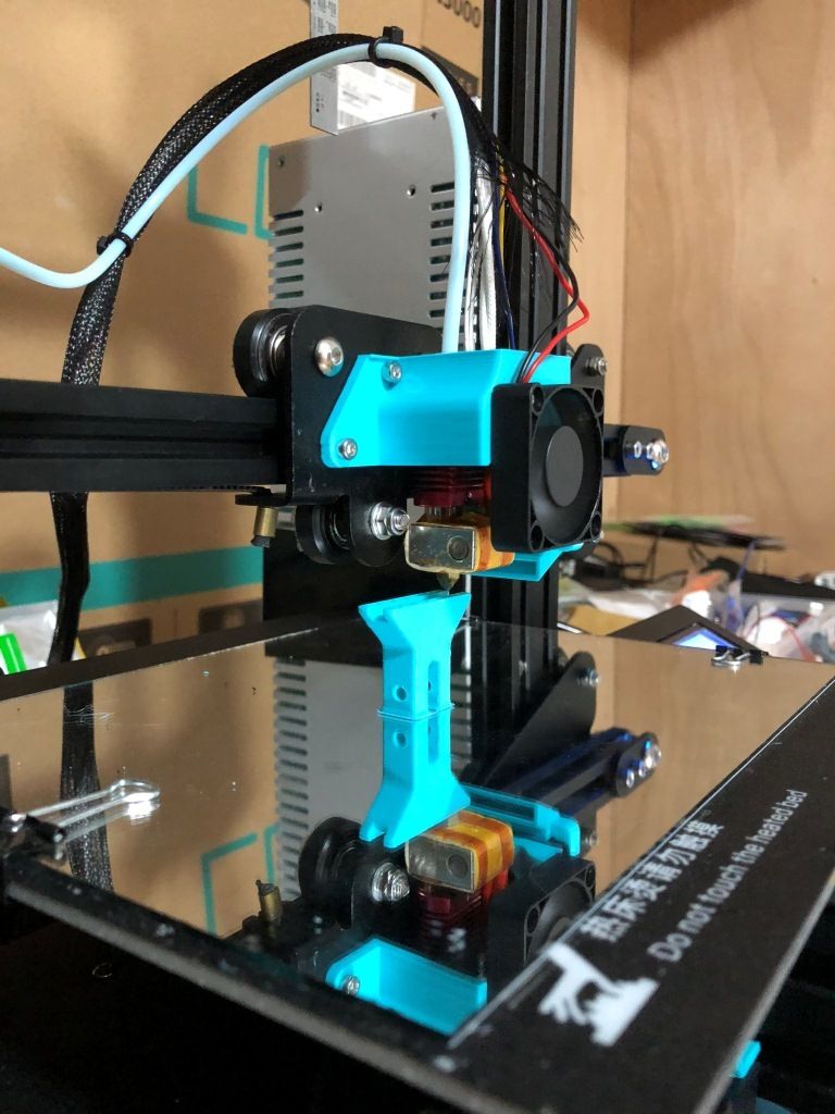 ..
..
Switch Alignment Jig
thingiverse
Jig used to align switches while soldering the Smaller Simone Giertz's Good Habit Tracker Hackaday.io project here: https://hackaday.io/project/78869-smaller-simone-giertzs-good-habit-tracker Not my project but I wanted to make my own boards and...
Switch soldering jig
thingiverse
I needed to solder 5 switches together and access wouldn't be easy if installed in the case; additionally the spacing needed to be right if done uninstalled as the wiring would be quite rigid. I therefore knocked up this jig to allow the switches to...
Switch JoyCon Grip
thingiverse
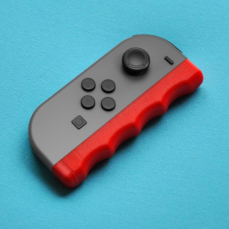
I designed a JoyCon grip based on the: Nintendo Switch JoyCon Small Grip by Bodacious_Bum, (https://www. thingiverse.com/thing:2437689), to also be able to house the: Nintendo Switch RCM Jig by ShadowX (https://www.thingiverse.com/thing:4095790),...
RCM
sketchfab
No description provided.
Switch Soldering Jig - 12 mm
thingiverse
This soldering jig makes it easier to solder wires to the leads of a 12 mm tactile switch. ...
Nintendo Switch Screen Protector Jig
thingiverse
Super simple design for a jig to help place a screen protector on the original Nintendo Switch. I'm always having trouble placing screen protectors and alignment is usually off. This helps a bunch. After doing the appropriate screen cleaning/prep,...
Giant Pinball Machine Made by Hacking Nintendo Switch Controllers with 3D Printing - 3DPrint.com
“Ever since I was a young boy I’ve played the silver ball…From Soho down to Brighton I must have played them all.” – Pete Townshend, The Who
Now that I’ve got “Pinball Wizard” stuck in your head, let’s talk about this classic arcade game. The concept is pretty simple: you use game paddles, or flippers, to manipulate the little metallic balls on the game field inside the glass-covered cabinet, or pinball machine, to score as many points as you can. It’s so popular that many gaming consoles like the hybrid Nintendo Switch, have their own versions, in case players can’t get themselves to an actual arcade—do those even exist anymore?
The Switch can be plugged into a docking system and played on a TV, or used as a mobile gaming device with a touchscreen interface. Naturally, many people have used 3D printing to hack the system, and customize the multi-use JoyCon controllers however they want, which brings us back to pinball. Maker Tommy Williamson is the founder of the Nerds&Makers community, which is exactly what it sounds like — the members visit the site to “showcase cool projects, to promote makers, to find inspiration, to teach, to learn and most importantly to connect with other makers and like-minded individuals.”
Williamson found that playing pinball on the Switch was difficult with the standard JoyCon shoulder buttons, which are decidedly not the typical flipper controls used to play the original game. He did what many a maker has done before, and used 3D printing to create a custom solution. The JoyCon dock he created, which he dubbed the SwitchPin, makes it much easier to play the game. Basically, the controller turns two buttons on the JoyCon into two different buttons for optimal pinballing.
“Sometimes two buttons really need to be two other buttons, and in those times we should not let anything get in the way of a creative solution,” Kotaku writer Mike Fahey wrote about Williamson’s creation.
The SwitchPin is an ingenious solution. Basically, Williamson modeled two blocks, and fitted them with pinball arcade flipper buttons. Then, he 3D printed the blocks out of black Hatchbox PLA on his Prusa i3 Mk3 3D printer; the buttons were printed in red, and he recommends using the printer’s quality settings due to the tight tolerances of the design. Once the print job was finished, he had to spend some time removing supports from the blocks, and then did a little sanding to, as he wrote on Thingiverse, “tweak things to be just right.”
He used 3/8″ x 5/8″ springs from a Harbor Freight box set to make the flippers work, and assembled the SwitchPin with M3 screws – no soldering required.
“I recommend drilling and tapping the frames, the center parts use nuts. I used M3 20mm and 25mm,” Williamson wrote. “To keep it from sliding around there’s small wells on the bottom for rubber pads. I used hemispherical ones from this pack.”
As you can see in the image above, there’s a slot for a JoyCon controller inside each block, and the controller’s shoulder buttons line up perfectly with the arcade button actuators.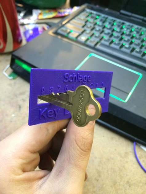 Then, Williamson added enough black plastic in between the two blocks to make the whole thing the length of his TV when on portrait mode. He removed the TV from the wall, set it on a table, placed the 3D printed SwitchPin at the bottom, set the Nintendo Switch to the correct view, and started playing the game the way pinball is meant to be played. It’s a pretty impressive setup.
You can get the 3D printing files to make your own SwitchPin pinball controller for free on Thingiverse. Take a look at the video below to see Williamson’s whole building process:
I was curious about what other interesting 3D printable Switch adaptations people have been making, so I searched a few 3D model repositories and found some interesting designs. Mechatronics engineer Julio Vazquez, also known as Vexelius, created these JoyCon adapters that allow disabled gamers to play with just one hand, and also came up with this Accessibility stand “to provide an easy to print and non invasive mod that will help disabled players enjoy a better experience.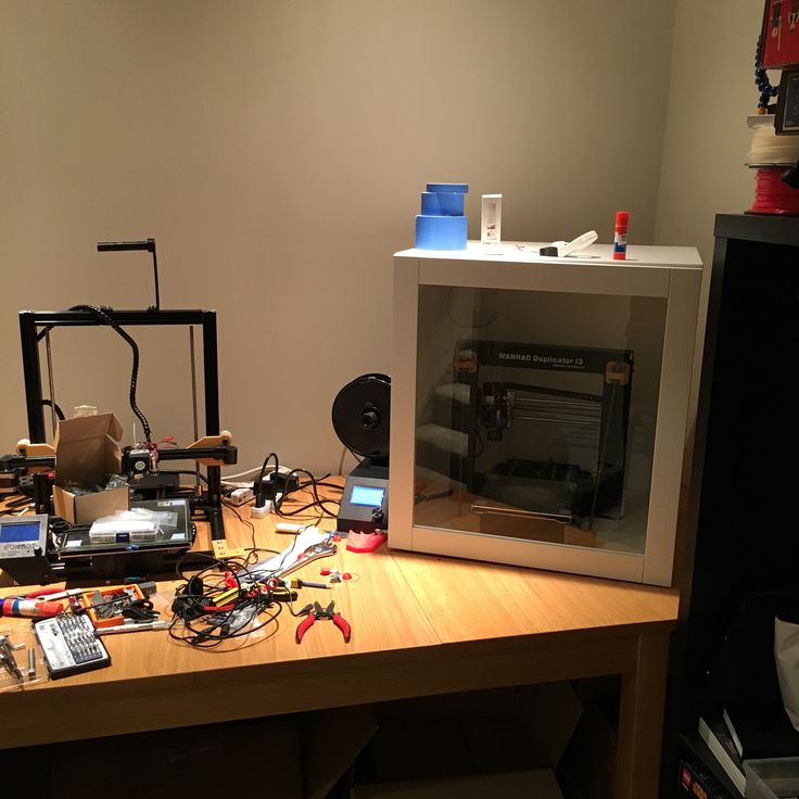 ”
”
“The SL and SR buttons, which are small and difficult to press are now easier to reach, thanks to a couple of extensions; and an optional cross-shaped cover for the buttons will help users that might not have the accuracy to press the small buttons in the Joy-Con,” Vazquez wrote.
On Cults 3D, I saw this JoyCon Wristband for playing the “Just Dance” game on the Switch, which has two slot sizes, and I also found two different versions of a Nintendo Switch Joy Con Controller Drink Holder.
(Images courtesy of Nerds&Makers)
Stay up-to-date on all the latest news from the 3D printing industry and receive information and offers from third party vendors.
Tagged with: 3d printed controller • 3d printed gaming accessories • 3D printing DIY projects • 3d printing game controller • gaming • hacking • Hatchbox • Joy-Con • JoyCon • Nerds&Makers • Nintendo Switch • pinball • Prusa i3 MK3 printer • Switchpin • thingiverse
Please enable JavaScript to view the comments powered by Disqus.
everything you need to know
3DPrintStory Reviews BLTouch sensor for 3D printer: everything you need to know
Automatic table calibration is a fairly common feature in desktop FDM 3D printers. However, most 3D printers with automatic table calibration use a non-contact inductive sensor, which is easy to install, operate and configure. These inductive sensors work well with metal 3D printer tables, but tables made from other common materials such as glass are virtually invisible to inductive sensors.
Perhaps it is because of this lack of inductive sensors that many people hear about BLTouch sensors: if you need to use a non-metallic 3D printer slot base but need automatic calibration, these sensors are a great option.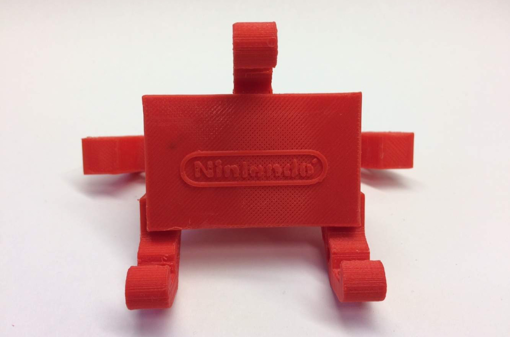 Another plus of these sensors is its high accuracy. BLTouch raw readings have one of the lowest standard deviations of any sensor type for automating 3D printer bed calibration.
In this article we will look at the BLTouch sensor, its advantages and how to use it for a 3D printer (by the way, there are many clones of BLTouch sensors, but the original design belongs to Antclabs from South Korea).
What is a BLTouch sensor?
According to Antclabs, the original manufacturer of the sensor, "BLTouch is an automatic table calibration sensor for 3D printers that can accurately measure the angle of the table surface." This sensor works on any type of surface, be it metal, glass, wood and others.
The 3D printer table tilt level sensor itself has a rather complex design. It consists of a microcontroller, a solenoid switch and a handpiece that is in direct contact with the table. The original BLTouch uses a Hall sensor for high accuracy, and this sensor, combined with the physical handpiece, allows it to be used with many types of tables.
In a sense, this sensor is equivalent to a microswitch mounted on a servo. When the tool head is lowered to "return" the nozzle in the Z-axis, the table pushes the tip slightly up, the Hall sensor is activated, and then the tool head rises.
TheBLTouch is one of the most accurate and reliable sensors available, so it's no wonder some manufacturers like MakerGear and CraftBot use this device on their high end 3D printers.
Now that we know exactly what we're dealing with, let's compare the BLTouch with the other two types of sensors.
Different types of sensors for automatic 3D printer table calibration
Inductive sensor
The key difference between inductive sensor and BLTouch is that the BLTouch sensor physically touches the table during the calibration process. The inductive sensor uses currents induced by magnetic fields to detect nearby metal objects, so there is no direct physical contact with the table.
But therein lies the problem: induction sensors only work with metal tables, as they only work when they come into contact with metal. So if you are using glass, then this type of sensor will not work for you.
Microswitch (mechanical limit switch)
Don't discount the old-fashioned physical microswitch either. Compared to the BLTouch, this sensor is less accurate and possibly less reliable in the long run because the measurement is dependent on physical parts that can wear out over time.
However, these mechanical switches outperform other options when it comes to cost and ease of setup. Since mechanical switches are very simple to implement, easy to set up and cheap, they have found quite a wide application.
Alternatives
Pinda Probe
Pina Probe is a sensor developed by Prusa Research which is an induction sensor with a thermistor to account for changes in bed temperature. The Pinda probe is specially designed for the Prusa line of 3D printers, which have special dot-mounted calibration markers on the table that help with alignment and skew correction.
This is said to be a very accurate sensor for 3D printers, and although there aren't many numbers on the internet, the reviews seem to be positive.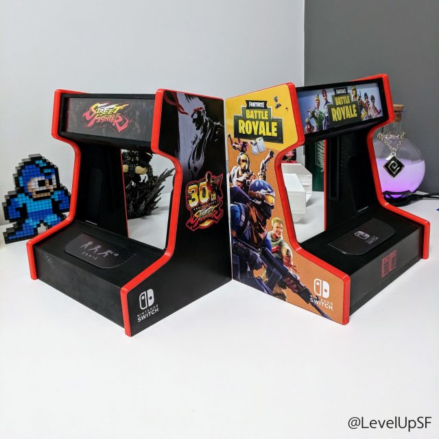 So it is worth considering that this is a good option if your 3D printer has a metal table.
Ezabl Pro
Ezabl Pro is a capacitive sensor manufactured. It comes with a connection board that uses an optical isolator to prevent high voltage damage to the motherboard in case of connection errors.
In terms of accuracy, it can measure to one thousandth of a millimeter, which is what 3D printers need. Ezabl Pro also has useful features such as double shielding that prevents any interference from other signals.
The main disadvantage of Ezabl Pro is the cost, which is about 65 dollars. But this sensor can work with glass tables.
Piezo Sensors
Piezo Sensor uses the piezoelectric effect to detect changes in force, pressure or strain and convert those changes into an electrical impulse. Precision Piezo is one of the few companies in the UK that makes piezo sensors for 3D printers. They have an accuracy close to 7 microns, which is pretty accurate for a 3D printer.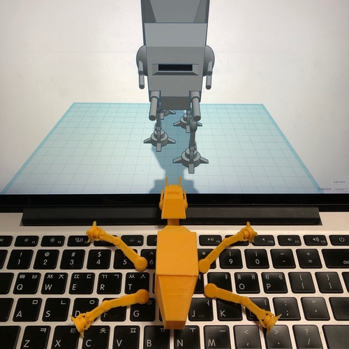
The advantage of the piezoelectric sensor is that a nozzle can be used as a sensing element without the need for additional components. In addition, a piezoelectric sensor can be placed on the print head or under the pressure platform. As for the price, it is in the same range as BLTouch.
BLTouch Sensor Setup Basics
Before you start modifying your 3D printer for BLTouch, you need to work through the following points.
Mounting the sensor
The BLTouch sensor must be installed as close to the print head as possible. You can find many designs available for download on the internet. If you would like to design the mounting structure yourself, be sure to read the BLTouch documentation to take into account the overall dimensions of the sensor.
Some users have experienced a problem where the nozzle hits the table on one side and prints perfectly on the other. The reason for this is that the BLTouch is mounted at an angle to the nozzle.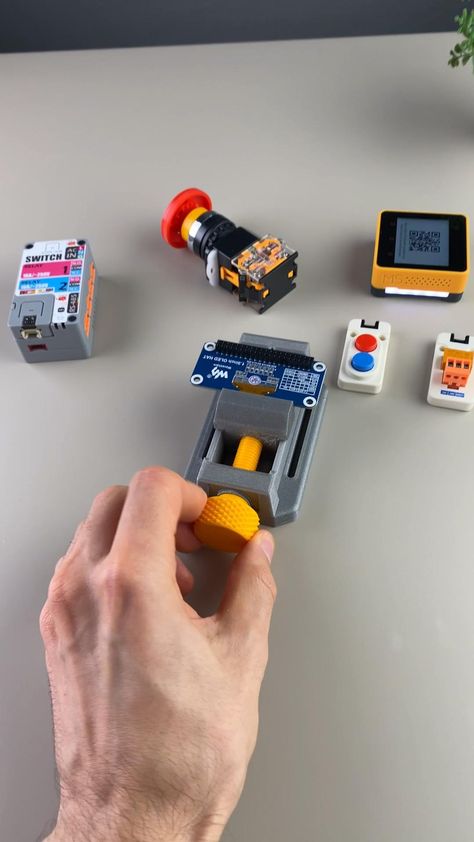 Therefore, when designing and installing equipment, make sure that the BLTouch is mounted perfectly at right angles and aligned with the nozzle.
After installing the sensor, be sure to record the distance between the BLTouch sensor and the nozzle center in both the X and Y directions.
3D Printer Firmware Configuration
To run BLTouch, you will need to change the 3D printer firmware in several places.
We used Marlin firmware version 1.1.9 which was updated in March 2020. Enter the marlin.ino file and go to the configuration.h tab.
The first step is to activate the BLTouch sensor by declaring it. Remove the two slashes to uncomment the define statement:
#define BLTOUCH
The next step is to set the BLTouch offset using the X and Y distances you should have measured when you installed the sensor. Z-shifting may seem like a more complicated procedure, as the BLTouch probe protrudes below the nozzle for direct measurements. You will need to find the distance between the sensor and the end of the nozzle when the sensor is fully extended.
Also, since the probe goes below the nozzle, the offset must be negative. We recommend setting it to around -2.5 for safe first runs and then adjusting. You need to change the values of the following lines to match your numbers:
#define X_PROBE_OFFSET_FROM_EXTRUDER 30 // X offset: -left + right [nozzles] #define Y_PROBE_OFFSET_FROM_EXTRUDER 20 // Y offset: -front + back #define Z_PROBE_OFFSET_FROM_EXTRUDER -2.5 // Offset Z: -below + above
After you're done with the offset, you'll need to choose a table alignment type. You can choose from five different compensation methods, below we will give an example using the bilinear method as it is easy to get started with.
To select the appropriate option, uncomment it by removing the slash. Please note that only one option can be left without comment. Your code should look something like this:
//#define AUTO_BED_LEVELING_3POINT //#define AUTO_BED_LEVELING_LINEAR #define AUTO_BED_LEVELING_BILINEAR //#define AUTO_BED_LEVELING_UBL //#define MESH_BED_LEVELING
You can also set the number of mesh points that you will base your calibration on. Default is 9points that form a 3-by-3 grid along the x and y axes. The number of points can be increased for more accurate results, but keep in mind that the probing time will also increase proportionally.
#if ENABLED (AUTO_BED_LEVELING_LINEAR) || ENABLED (AUTO_BED_LEVELING_BILINEAR)
// Set the number of grid points per size.
#define GRID_MAX_POINTS_X 3 #define GRID_MAX_POINTS_Y GRID_MAX_POINTS_X
Testing
After setting up the firmware, you will need to check if the BLTouch is working properly by doing a basic test. Once it's complete, you can start adjusting the Z offset. There's a great video from 3DMakerNoob that walks you through the process step by step.
Slicer setup
Be sure to add the G29 command to your Gcode right after the G28 command.
Troubleshooting
Troubleshooting
The creators of the original BlTouch at Antclabs mentioned that the original sensors come with a QR code built into the circuit board on the back.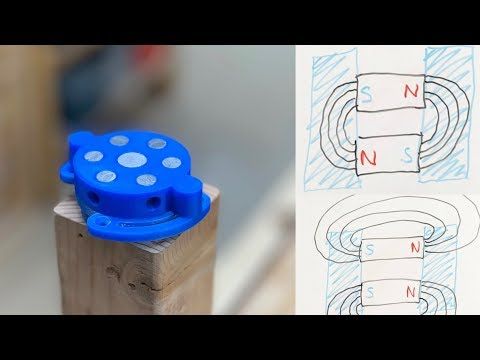 Other Chinese manufacturers, called TL Touch and 3D Touch, are also known to produce lower quality products, resulting in poorer quality. When buying online, be sure to purchase from one of the authorized resellers that are listed on the Antclabs website.
Known Issues with BLTouch Sensor
The latest version of BLTouch V3 had issues with Creality printers where it did not work properly. The Marlin firmware developers worked closely with Antclabs and determined that certain changes needed to be made to the firmware.
An excellent tutorial video on how to fix this problem was made by Teaching Tech. After making changes, many users finally solved the problem.
Disadvantages of BLTouch
Although the BLTouch is an extremely accurate level sensor, it also has several disadvantages.
When using the BLTouch, it is important that there is no debris on the surface of the bed.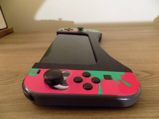 A mechanical sensor detects the surface of the table and any damage or debris on the surface will result in inaccurate readings.
The BLTouch is also known to suffer from interference from currents in the hot end heater wires. This interference causes incorrect BLTouch readings. The Marlin firmware has a special line of code that will help you turn off the heaters while the sensor is triggered. To activate it, find and uncomment the following:
#define PROBING_HEATERS_OFF
Set up the Marlin firmware and upload it to the 3D printer
Many 3D printers run the popular firmware Marlin . The firmware is pre-configured for Ultimaker Original. Let's analyze the basic settings for other 3D printers.
The firmware is located at this address. Downloading. We press the button Download ZIP . The archive Marlin-Development.zip is downloaded. Unpack it to the selected folder.
Now download Arduino IDE to fix and upload firmware to 3D printer . Link. We press on Windows Installer . Installer arduino-1.6.0-windows.exe is downloaded. Run it and install the environment Arduino IDE .
Go to the firmware folder and run the file Marlin.ino .
Opens Arduino IDE with firmware. We need a tab Configuration.h .
At the beginning we see references to the calibration of the 3D printer . Scroll further and read: ' This is a configuration file with basic settings. Select controller type, temperature sensor type, calibrate axis movements and configure limit switches.'
Let's start with controller selection (MOTHERBOARD). The list of controllers is in the tab boards.h . Click on the triangle in the upper right corner and select boards.h .
Now look at the installed electronics. Here are some types of boards:
Melzi
RAMPS 1. 4
4
I have RAMPS 1.4.
Replace in configuration.h 'MOTHERBOARD BOARD_ULTIMAKER' with 'MOTHERBOARD BOARD_RAMPS_13_EFB'.
#ifndef MOTHERBOARD
#define MOTHERBOARD BOARD_RAMPS_13_EFB
#endif
Next select temperature sensor - thermistor . We see a large list of '//// Temperature sensor settings:'. I have an E3D-v5 hotend and a Chinese thermistor on the table. For E3D-v5 I choose '// 5 is 100K thermistor - ATC Semitec 104GT-2', for the table '// 1 is 100k thermistor - best choice for EPCOS 100k'. If the type of thermistor is unknown, you can choose 1, and if you don’t like the temperature, you can choose any and test. I change.
100K thermistor - ATC Semitec 104GT-2
Ordinary Chinese thermistor 100K
Hotend maximum temperature limitation '#define HEATER_0_MAXTEMP 275'.
Hotend minimum temperature limit '#define EXTRUDE_MINTEMP 170'.
If the limit switch is not connected as standard and its state needs to be inverted , then this can be done in the firmware without soldering the wires. Values false or true . The command M119 (for example in Pronterface ) shows the state of the limit switches. My limit switches are only in position HOME on MAX .
In position HOME
In position different from HOME on all axes
I did not need to change anything.
const bool X_MIN_ENDSTOP_INVERTING = true;
const bool Y_MIN_ENDSTOP_INVERTING = true;
const bool Z_MIN_ENDSTOP_INVERTING = true;
const bool X_MAX_ENDSTOP_INVERTING = true;
const bool Y_MAX_ENDSTOP_INVERTING = true;
const bool Z_MAX_ENDSTOP_INVERTING = true;
Change the direction of rotation of stepper motors , values false or true . Correct movements of the nozzle relative to the table :
- Along the X axis - to the left '-', to the right '+'.
- Y - forward '+', backward '-'.
- On the Z axis - approach '-', removal '+'.
- Extruder. Extrude - thread extrusion, Reverse (retract) - rollback, thread retraction.
#define INVERT_X_DIR false
#define INVERT_Y_DIR false
#define INVERT_Z_DIR false
#define INVERT_E0_DIR true
Next comes setting the limit switches 9014. We need to find out where they are located . How to find out? The origin is in the near left corner on the table surface , if the nozzle is brought to this point, then the limit switches MIN would work, if to the far upper right, MAX would work. I have three limit switches MAX at position HOME , so my settings are
// Sets direction of endstops when homing; 1=MAX, -1=MIN
#define X_HOME_DIR 1
#define Y_HOME_DIR 1
#define Z_HOME_DIR 1
Set travel dimensions to , after initialization at position HOME . Here we set the dimensions of the working area in X and Y, as well as the setting of the nozzle relative to the table.
If when the nozzle touches the table, the limit switch is triggered ( MIN ), as in Ultimaker Original, then the nozzle is adjusted relative to the table by moving the limit switch, and in '#define Z_MAX_POS' we write the coordinate value at the maximum distance of the nozzle from the table. The coordinate can be found by command M114 or by looking at the display screen.
If the Z limit switch is triggered at the maximum distance of the nozzle from the table ( MAX ), then you need to find the Z dimension yourself. Set the value '#define Z_MAX_POS' to be initially higher than the norm, for example 250 with a dimension of 200 mm. We lower the nozzle until it touches the table and on the display (or by command M114 ) we see the coordinate greater than zero, now subtract the obtained coordinate from the set large value and get the Z dimension, which we will now write in '#define Z_MAX_POS'. Based on the results of printing the first layer, this value can be corrected. . The extruder is also an axis. My settings.
Now let's see how I got them . All axes are stepper motors 200 steps per revolution, 16 micro steps per step (set by jumpers on the board). On the X and Y axes there is a GT2 drive belt with a 2 mm pitch and 20 teeth pulleys , in total we get the formula (200 * 16) / (2.0 * 20). Along the Z axis, there are M8 studs with a thread pitch of 1.25 mm, the total formula is 200 * 16 / 1.25.
We find specifications (datasheet) for installed stepper motors . We see that in one step the shaft rotates 1.8 degrees, which means 360 / 1.8 = 200 steps per full turn. This parameter is the same for most stepper motors installed in home 3D printers.
Belt profiles commonly used on 3D printers and their step . Original here, page 61.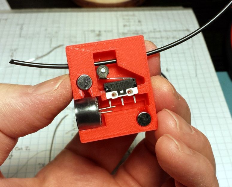
Pulley
How to measure screw pitch ? We measure the section of the screw and count the turns on it, then divide the length of the section in millimeters by the number of turns 20/16 = 1.25 mm. For a more accurate result, we measure the section of maximum length.
The setting of the extruder depends on the reduction ratio and the feed gear diameter. We will select experimentally , after the first firmware upload to 3D printer . Unscrew the nozzle and reduce the minimum nozzle temperature limit to 5 degrees '#define EXTRUDE_MINTEMP 5'. Now the extruder will work with a cold nozzle, which is what we need. We do not change the extruder settings yet. For configuration, I use the Pronterface program. To begin with, we set 50 mm and the speed is 100 mm / s. 50mm is the length of the bar that goes through the extruder. We measure the length of the rod passed through the extruder with a ruler or caliper.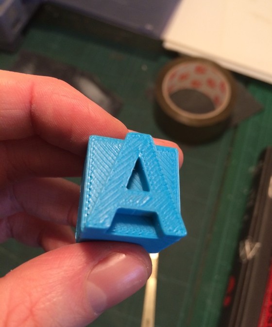
Selecting the extruder setting, we achieve the exact figure on a reasonable length of the rod, for example 300 mm. After setting , return the minimum temperature limits '#define EXTRUDE_MINTEMP 170'.
The following digits are the maximum travel speed limit for the axes . On X and Y I put 200 mm, I don’t touch the rest.
#define DEFAULT_MAX_FEEDRATE {200, 200, 5, 25}
Axis acceleration setting . At high accelerations steps may be skipped . You can pick it up by driving in the Pronterface program along the axes at a given speed. Here are my settings:
#define DEFAULT_MAX_ACCELERATION {1000,1000,100,10000}
#define DEFAULT_ACCELERATION 1500
It remains to activate LCD with SD card . I found my display on RepRap.org and identified it as RepRapDiscount Smart Controller .
Uncomment (remove double slashes) the following lines:
#define ULTRA_LCD
#define SDSUPPORT
#define ULTIPANEL
#define REPRAP_DISCOUNT_SMART_CONTROLLER
When setting zero in Z, I encountered the fact that after each initialization of HOME , the position of the nozzle above the table changed slightly. Digging through the firmware, I found a parameter responsible for initializing the limit switches. Go to tab Configuration_adv.h and look for the line '#define Z_HOME_RETRACT_MM 2', change the value 2 to 5 and don't remember this parameter anymore.
It's time to upload the firmware to the controller. To do this, you need to correctly set the type of board and the number COM of the port in Arduino IDE . The card type and port number will be displayed at the bottom of the window. Don't forget to save changes (Ctrl+S) .
RAMPS
MELZI
0145 Arduino IDE you need to copy and replace all from the firmware folder 'Marlin-DevelopmentArduinoAddonsArduino_1.5.xhardwaremarlinavr' to the Arduino IDE 'C:Program Files (x86)Arduinohardwarearduinoavr' folder. After that, it becomes possible to select the board Sanguino (base board for Melzi ) and the desired processor type . I don't have a Melzi board, so I can't check.
For fill firmware click on the circle with an arrow.
The progress of uploading the firmware is displayed by the indicator
For this I use Pronterface . We enter the command ' M303 E0 C8 S260 '. Where M303 is the calibration command, E0 is the hot end, C8 is the number of heating-cooling cycles, S260 is the typical operating temperature of the nozzle.
Last results are written to firmware .
#define DEFAULT_Kp 12.22
#define DEFAULT_Ki 0.58
#define DEFAULT_Kd 64.08
Using the same scheme , we calibrate the table PID . Command ' M303 E-1 C8 S110 '. Where E-1 is the table, S110 is the typical table heating temperature. The last results are written to firmware . My table heats up very slowly and therefore I have to restart the command due to a Timeout error.
#define DEFAULT_bedKp 105.94
#define DEFAULT_bedKi 4.97
#define DEFAULT_bedKd 564.11
The parameters set in the firmware can be found in the program Repetier-Host through the menu ConfigurationConfiguration EEPROM . First you need to specify COM port in the settings and click the button ' Connect '.
When connecting a 3D printer to program Pronterface the list of firmware parameters is displayed on the right side of the window
Also the parameters can be seen on the LCD display . Via menu ControlMotion .
Would love to see similar instructions for Delta printers, CoreXY and H-Bot 3D printers.
Criticisms are highly welcome as the instructions will be posted on the 3D Wiki later on.
Learn more


