Sequential 3d printing
Sequential printing | Prusa Knowledge Base
Relevant for
:
MINIMINI+MK2.5MK2.5SMK2SMK3MK3SMMU1MMU2SPlus 1.75 mm
Last updated
7 months ago
This article is also available in following languages:
This option is not available when PrusaSlicer is in Simple mode.
When printing multiple objects at once, you can choose to finish them sequentially, one at a time. This can minimize oozing and strings running between the prints. It can also prevent losing multiple half-finished prints if one of the objects detaches from the print bed.
You can turn this feature on by enabling Print settings - Output options - Complete individual objects.
Press the E key to see the order of objects in the 3D view.
You can change the order by dragging and dropping objects in the Object list. The top-most object in the Object list will be printed first, and the bottom-most last.
You'll have to check on the printer regularly, with every object there is a chance that the specific part won't stick to the print bed.
Collisions
With sequential printing, there is a possibility of collisions between the print head and one of the finished prints or between the X-axis and one of the finished prints. PrusaSlicer will try to warn of such cases, but even if you get no warning, you should try to avoid possible collisions as much as possible.
Print objects from front to back, from left to right, and from lowest to tallest part
to minimize the chance of collision with the extruder and the X-axis.
If PrusaSlicer detects a collision, it will visualize it with a red highlight of the overlapping regions.
To help PrusaSlicer detect collisions, specify the Extruder clearance settings.
Radius
The radius of the cylindrical clearance around the extruder.
Height
The vertical distance between the tip of the nozzle and the X-axis rods (or the lowest part which may interfere with a finished print).
PrusaSlicer wants all objects to be below the extruder clearance height except for the last object, which can be as tall as the printer's max Z.
Visual representation of the default parameter, creating a keep-out zone of 45mm radius and 20mm height around the nozzle (thanks to David Renaud)
The collision detection logic is pretty basic and will sometimes prevent you from Exporting printable G-code. It's up to you to take responsibility and increase the height tolerance.
Example
Height clearance is 20mm.
The object is 25mm tall.
Objects can be printed sequentially, but the current collision logic does not distinguish between the left scenario (not printable, collision with the X-axis rod), and the right scenario (printable). So you have to change the value manually (height clearance).
Multi-Part Printing
In this tutorial, we will be teaching you everything you need to know about printing multiple parts at once on your 3D printer. Many new users focus on printing only one part at a time until they are happy with the results, but as you get more experienced you also have the option of importing multiple STL files into the software and printing them simultaneously. This can save a lot of setup and post-processing time. For example, imagine printing all 32 pieces of a chess set overnight and then coming back to an entirely finished game set in the morning. It would take a lot more work to print each piece one at a time.
The Simplify3D Software gives you a wide array of options for multi-part printing so that you can choose the best method for your specific needs. There are 3 different multi-part printing modes that we will be talking about.
- Single Process Printing Mode
- Multiple Process, Continuous Printing Mode
- Multiple Process, Sequential Printing Mode
The number of processes refers to the number of FFF processes that you will be configuring to control the print settings for your parts. The Simplify3D Software has the unique ability of allowing you to use different settings for each model you print. For example, if the King and Queen pieces in your chess set require different settings, you can easily configure this in the software and still print these parts simultaneously. This is one of the big advantages of the software and we will cover this in more detail later on.
Single Process Printing Mode
The first technique we will be covering is the single process printing mode. This is the easiest of all three methods and one that most users are probably already familiar with. This is the technique you would want to use if all of your parts use the exact same slicing settings and you don’t need the reliability and performance benefits that sequential printing offers. For example, you might be printing four identical LEGO bricks, like in the model found here. The models are small, simple, and you can arrange them close to one another to prevent excessive oozing while moving between parts. In this case, the single process printing mode is a great technique to use.
To begin, download and import the lego block STL file into the software. If you need to rename a model after importing, just double click on it to enter a new name. To make additional copies of this model, go to Models > Duplicate Selected Model. Make three identical copies and arrange them with a millimeter or two of spacing between them. Next, add a new FFF process and configure your slicing settings for the LEGO block models. In our case, we used medium quality, 60% infill. The last thing we need to do is select what models this specific FFF process will use. To do this, click the Select Models button in the bottom left of your FFF Settings. If we want to print all four pieces, make sure all four items are selected in the list or simply click the Select All button. Click Prepare to Print! to see the newly created printing instructions.
If you look at the G-Code preview, you should notice that the extruder prints all four pieces simultaneously. For each layer, the extruder prints one section of each block and then repeats this process. This results in a lot of movement back and forth between the different pieces, but as long as they are positioned fairly close together this should be okay.
Multiple Process, Continuous Printing Mode
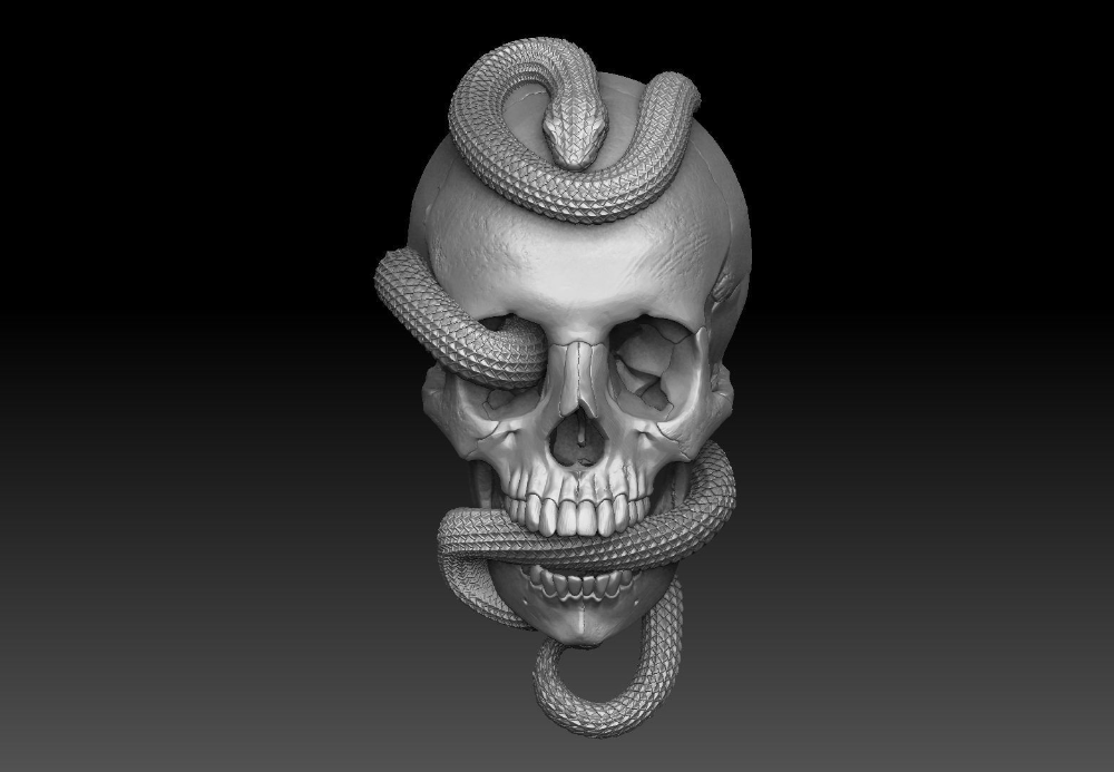
For the next printing mode, we will be returning to the chess set example we described earlier. Go ahead and download the Knight and Pawn chess pieces. Import both of the STL files into the software and have a look at the features of the different models. You will notice that the pawn is very simplistic with gradual curves and features. The knight piece, on the other hand, has several fine detailed features such as eyes, hair, and teeth. It also has a fairly severe overhang on the chin of the model. In this case, it might be advantageous to use different slicing settings for these two models so that we can make sure they both print with the best quality possible.
As we learned in the previous section, we can use the Select Models button to determine what models a given FFF process uses. We could easily create one FFF process for the pawn and a second for the knight. That will give us more flexibility by letting us use the optimal settings for each model. First, let’s create the settings for the pawn. Create a new FFF process and call it “Pawn Process.” Use the Select Models button to make sure that this FFF process only applies to the pawn STL file. Now go ahead and configure the optimal settings for this model. We used 0.3mm layer heights with 3 outline perimeters and 0% infill. This will allow the part to print very quickly, which should be fine for the gradual rounded surfaces. If you want, you can Prepare and Preview this single process to make sure the pawn settings are configured properly.
Next, we will configure the settings for the knight. Add a new FFF process and call it the “Knight Process.” As before, use the Select Models button to make sure that this process only applies to the knight STL file. The settings for this part will be quite different than our pawn. We added support material for the chin overhang, used 0.15mm layer heights to help improve the quality of the fine features, and used 40% infill to help support the large flat surfaces at the top of the model. Save your settings and return to the main workspace.
The last thing we need to do is click the Prepare to Print! button to generate the printing instructions for our multiple FFF processes. The software will detect that you have multiple FFF processes and ask you which ones you want to merge together. Select both the “Pawn Process” and the “Knight Process.”
At the bottom of this window there is also an option to configure how these multiple processes will be combined. If we select the continuous printing mode, each process will be merged together, one layer after another. The result will look very similar to the single process printing mode that we described in the previous section, however, we now have optimized settings for each individual model.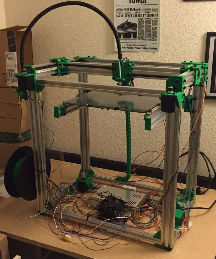
Multiple Process, Sequential Printing Mode
The last printing mode we are going to talk about is sequential printing. This is a very useful printing mode that can help improve reliability and print quality, but you may need to re-arrange your models to use this technique. During sequential printing, the software will print multiple layers of a single model before transitioning to the next model. So it might print 30 layers of our pawn model before it moves over to the knight and prints 30 layers of it. This significantly reduces the amount of movement between models which results in a much cleaner surface finish. It also improves the reliability of the overall print since one model could actually separate from the build plate and fail without ruining the entire batch of parts. The image to the left illustrates the difference between the continuous (left) and sequential (right) printing modes. The thin red lines represent rapid movements where the nozzle is moving to a new location to begin printing. As you can see, the sequential printing mode results in much fewer movements between parts for faster and better looking prints.
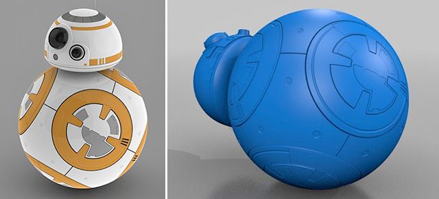
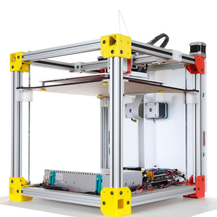
So now that you know how sequential printing works, we need to check your hardware to determine how to re-arrange your parts. If the nozzle does not have sufficient clearance, your printer will end up colliding with one of the previously printed parts. The image to the left shows several common extruder configurations. Keep in mind that there may be external accessories such as fans or structural frames that reduce the available clearance of your extruder. The orange lines in the left image represent two parts being sequentially printed side-by-side. The spacing between these parts is an additional factor that determines if sequential printing would be successful. For example, the two bottom configurations do not have sufficient clearance with the current part spacing. However, if the spacing between the orange parts was doubled or tripled, the two bottom configurations would gain additional clearance.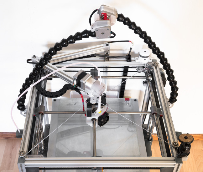
To help illustrate this in more detail, let’s look at some real-world hardware. The Replicator 2 is a great example of how part spacing can affect your sequential printing clearance. The Replicator 2 blower fan sits right next to the extruder nozzle, which means that this printer has very little sequential printing clearance if the parts are arranged side-by-side and are only a few millimeters apart (see top image). However, if the part spacing is increased, the blower fan is no longer an issue and the X-axis rails become the new limiting factor (see bottom image). You could also arrange the parts so that one is positioned in front of the other, instead of side-by-side. As you can see, most printers will be able to use sequential printing, but it may require some extra planning and forethought to make sure the models are arranged in such a way to avoid any potential collisions.
Now that you have determined the best way to arrange your parts, the sequential printing setup process is very easy.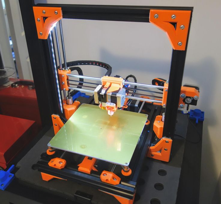 You can follow the exact same steps outlined in the Multiple Process, Continuous Printing Section, however, we need to select a different option when we finally prepare our FFF processes. Instead of selecting the continuous printing mode when we choose what processes to prepare, we select the sequential printing option. This requires us to enter a value for the vertical clearance that was described above. For the Replicator 2 example, we have a measured clearance of 12mm, assuming the parts are far enough apart to avoid collisions with the blower fan. Enter the appropriate value for your printer and then press OK to create the combined G-Code file. If you followed these steps correctly, you can now enjoy better looking and more efficient multi-part prints!
We have now covered all of the multi-part printing modes available in the Simplify3D Software. Next time you have multiple parts to print, give these great time-saving techniques a try!
View the Complete Article Library
90,000 Simplification of work with a 3D printer using GCode macroContent
-
- G-Code structure
- GCode command
- G-command
- M-command
- Macro types for 3D printer 9000 9000 9000 9000 9000 9000 9000 9000 Start
- Between Layers
- End
- Special
If you look in the dictionary of computer terminology, then a macro (or macro command) is a software algorithm of actions recorded by the user. That is, by definition, the computer must repeat the actions of a person. But in 3D printing, the term has a different meaning. Instead of recording and repeating human actions, the 3D printer will also execute commands, but now they will be written by hand, and not using a slicer. This allows you to directly control the actions of the printer, bypassing the standard way of slicing the model with a slicer. If you look at the GCODE file with notepad or any other text editor, you will see thousands and even tens of thousands of lines with a combination of letters and numbers. It may be scary, but in fact, almost any macro can be written in 5-10 lines. The main thing is to understand the order of writing a separate command.
Structure of G-code files
Each GCODE file can be divided into 2 parts: the comment that occurs at the beginning of the program and after the commands, and the commands themselves. Consider the example of a model sliced using PrusaSlicer (Version 2.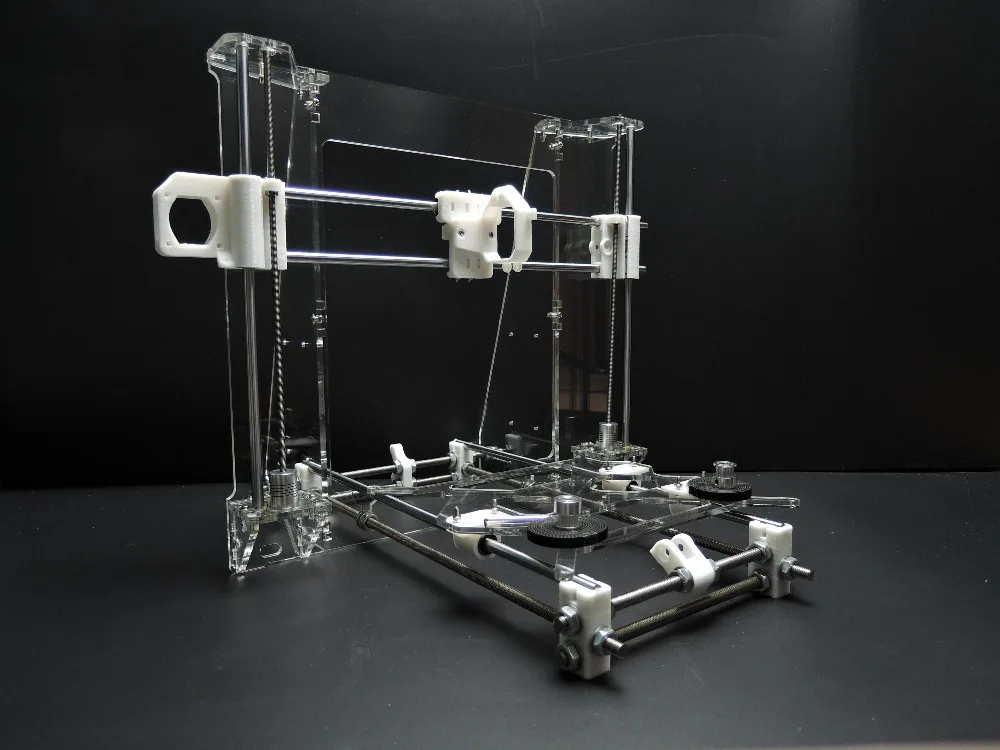 3.0).
3.0).
In the first line we are greeted by the name of the slicer, its version, date and time of slicing:
; generated by PrusaSlicer 2.3.0+win64 on 2021-04-22 at 12:31:50 UTC
Please note that at the very beginning of the line there is a semicolon sign, it indicates a comment. Everything that is in the line before it is read by the printer, but it does not pay attention to the fact that after it.
Next, we see several lines that show us the line width settings that the slicer used to slice the model. All of them are comments.
; external perimeters extrusion width = 0.45mm
; perimeters extrusion width = 0.45mm
; infill extrusion width = 0.45mm
; solid infill extrusion width = 0.45mm
; top infill extrusion width = 0.40mm
; first layer extrusion width = 0.40mm
After that there are lines that describe the initial temperatures, the command for finding the zero point of coordinates and the commands for moving.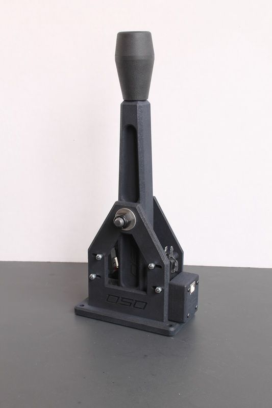 All commands that are involved in the beginning and the process of printing will be discussed further.
Tip: Many slicers, when slicing the GCODE for the printer, leave comments in the file indicating the layer change and / or its number. This will help in orienting in commands during manual editing.
Gcode command
Many are mistaken, calling this language for the operation of a 3D printer a programming language. In fact, this is a generally accepted format for working with CNC machines, including 3D printers. Each command is on a separate line and represents the name of the command (letter and number) and its parameters (also letters and numbers). For example, a command to move the nozzle to a certain coordinate with plastic extrusion:
G1 X101.912 Y136.607 E2.04825
G1 - team name
X101.912 - X coordinate
Y136.607 - Y coordinate
E2.04825 - amount of extruded plastic
All commands are divided into two main types:
-
G commands
-
M commands
There are other few types, but they are not used in 3D printers, so we will omit them in this article.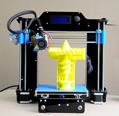
G commands
All commands in this group are for movement or calibration. A 3D printer does not use all of them, and not every 3D printer uses the same commands as another. For example, there is a command to auto-calibrate the table. Obviously, if this function is not provided for in your printer by design, then this command will not be executed. Below is a table of the most popular G-commands:
| Team | Options | Description |
|---|---|---|
| G0 | X - X coordinates | Moving without plastic extrusion |
| G1 | X - X coordinates | Moving with plastic extrusion |
| G4 | S - time in seconds | Pause |
| G28 | X-axis X | Moving to zero coordinates. If parameters are specified, then parking only along the specified axes |
| G29 | The parameters differ depending on the firmware. | Automatic construction of a table height map |
| G90 | - | Transition to absolute coordinate system (all coordinates are relative to zero) |
| G91 | - | Change to relative coordinate system (all coordinates are relative to the current position of the nozzle) |
| G92 | X - X coordinates | Set position without movement and extrusion |
M commands
These commands are auxiliary. They are mainly related to setting and calibrating temperatures, working with files, and setting up movement parameters.
| Team | Options | Description |
|---|---|---|
| M17 | X - motors according to X | Supply power to all motors if no parameters are specified. Otherwise, only the specified |
| M18 | X - motors according to X | Power off on motors Command reverse M17 |
| M20 | - | Listing files from an SD card |
| M21 | - | Memory card initialization |
| M22 | - | Disabling the memory card |
| M23 | After the command enter the name of the file | Selecting a file from the SD card |
| M24 | - | Start execution of file selected with M37 |
| M25 | - | Pausing SD Card Printing |
| M28 | After the command enter the name of the file | A file with the specified name is created or overwritten, all commands that are entered into the printer via a wired connection will be written to it |
| M29 | After the command enter the name of the file | The file with the specified name is saved. |
| M30 | After the command enter the name of the file | Deleting a file with the specified name |
| M82 | - | Switching to absolute mode for the extruder |
| M83 | - | Switching to relative mode for the extruder |
| M92 | X - value on X | Set the number of steps per millimeter for each specified motor |
| M104 | S - nozzle temperature | Set the nozzle temperature without waiting for heating up to the set temperature |
| M105 | - | Print nozzle temperature to console |
| M106 | S - rotation speed (from 0 to 255) | Turn on fan with speed indication |
| M107 | - | Turn off the fan |
| M108 | - | Cancel waiting for the nozzle to heat up to the temperature specified in M109 and M190 |
| M109 | S - nozzle temperature | Set the nozzle temperature and wait for heating to the set temperature |
| M112 | - | Emergency stop: |
| M119 | Xn (1/0) - X axis limit switch 1 - invert value | Get the status of the limit switches on the axes, if parameters are not specified |
| M140 | S - table temperature | Set the table temperature without waiting for heating to the set temperature |
| M190 | S - table temperature | Set the temperature of the table and wait for heating to the set temperature |
| M200 | D - diameter (in millimeters) T - extruder number | Set filament diameter |
| M201 | X - acceleration for the X axis | Setting accelerations along the axes |
| M205 | X - jerk for X axis | Setting the jerk along the axes |
| M206 | X - offset along the X axis | Setting the offset relative to the limit switches |
| M300 | S - frequency in Hertz P - duration in milliseconds | Emits a beep at a specified frequency for a specified time |
| M301 | H - heater number | Set the value of PID parameters for a given heater |
 All further commands are executed as usual.
 Some of the above commands can be used before printing to evaluate the status of the printer, such as M20 and M119.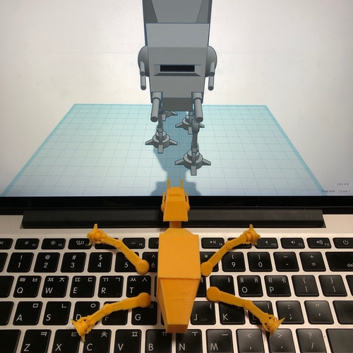 But many other commands are used to create macros, which we will describe next.
Types of macros for 3D printers
Like any other text document, GCODE files can be edited in Notepad. But for this you need to open the file every time, find the desired section and enter your macros. Instead, many slicers offer to manually enter macros, which will then be automatically inserted at the beginning, end or middle of the GCODE file. PrusaSlicer has the most flexibility - you can add a macro in it at the beginning, at the end, before and after layer changes, during a pause and between objects in a sequential print. Next, we will look at the most popular and convenient macros.
Initial
All macros of this type are designed to prepare the printer before printing. For example, with a single M301 command, you can set the PID on the printer for different temperatures. This can be very important, as the PID depends not only on the characteristics of the printer and its design, but also on the temperature of the print. If the hot end is very inert, then the PID values for different temperatures will differ slightly, so it makes no sense to change them every time. But if the hot end has low inertia, then the difference in PID coefficients for different temperatures is large enough to spoil the model due to temperature jumps. You can read more about PID tuning in the article on choosing the print temperature on our website. Once you find the value of the PID parameters for the temperatures you print most often, they can be substituted into the initial GCode. In PrusaSlicer, this can be done in the "Printer Setup" window, inside the "Custom Gcode" tab.
For convenience, you can create several printer profiles for different temperatures at once.
Loading filament
If you change the plastic every time you print, then for convenience you can use a small macro to change / refill the filament before printing:
G91; setting the origin relative to the last position
G1 E-100 F2400; Pulling out the filament
G4 S15; Pause for 15 seconds
G1 E100 F2400; Filament loading
G90; Transition to absolute coordinates
G92E0; Setting the extruder coordinate to zero
The value of the E parameter in the two G1 commands must be matched to your printer.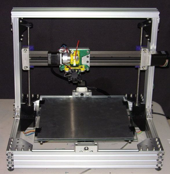 If you have a bowden extruder, then measure the length of the tube in millimeters and add 30-50 millimeters, then insert the resulting value into parameter E. If you have a direct extruder, you can insert a value of 50-70mm. Paste all the received code into the “Starting G-code” window after the standard commands.
Attention: after each change, do not forget to save the profile!
Between coats
This group contains macros that directly affect the printing process. They are often the most difficult, due to the need to manually edit the GCode file in notepad or other text editor. But in fact, there is nothing complicated about this, because each such file has comments that make it easy to find the desired section of code. For example, you can add a sound signal when changing layers. To do this, use the M300 command:
- M300 S500 P800
It should be borne in mind that the simplest speaker is installed in the printer, so you should not specify a frequency below 500 Hz, as the sound will be quieter and greatly distorted.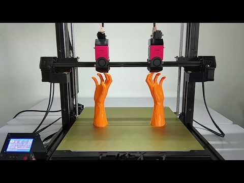 You can use this site to select the frequency. The square waveform most closely resembles the sound of a speaker. Once you have chosen the appropriate frequency and time, the resulting string can be pasted into the “G-code executed on layer change” window.
Filament change
This macro allows you to print one model in several colors on a printer that has one extruder. There are only 2 limitations: the color will change exactly at the border between the layers, and with each layer change, you need to manually change the filament.
First you need to determine the place to change the layer. To do this, calculate the height at which the boundary between the layers is located. This is easy to do with the formula:
Layer change height = layer number * layer height (in millimeters).
After you find the height, you need to open the Gcode file and find the first line in it, which contains the Z parameter with the desired layer height. For example, we need to change the color of the calibration cube on the tenth layer, while we print with a layer height of 0.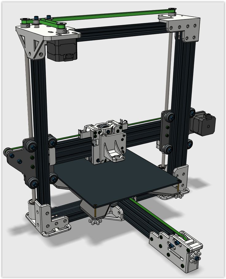 2 mm. So in the Gcode file you need to find the first line where there is Z5. Then, after the comments that the slicer put, you need to insert the following macro:
G91; transition to relative coordinate system
G1Z5; raising the nozzle by 5 mm
G90; change to absolute coordinate system
G1 Y10 X10 F1000; moving to the edge of the table
G4 S60; pause 60 seconds (at this time you need to insert the plastic)
G91; transition to relative coordinate system
G1 E100 F100; filling plastic
G92E0; zeroing extruder coordinates
G90; change to absolute coordinate system
In the end, your file should look something like the image below:
If you translate these commands into human language: as soon as the next layer begins, the printer raises the nozzle and moves it to the edge of the table. It then waits 60 seconds for you to replace the plastic. After that, the printer will extrude 100mm of loaded plastic to stabilize the flow and continue printing.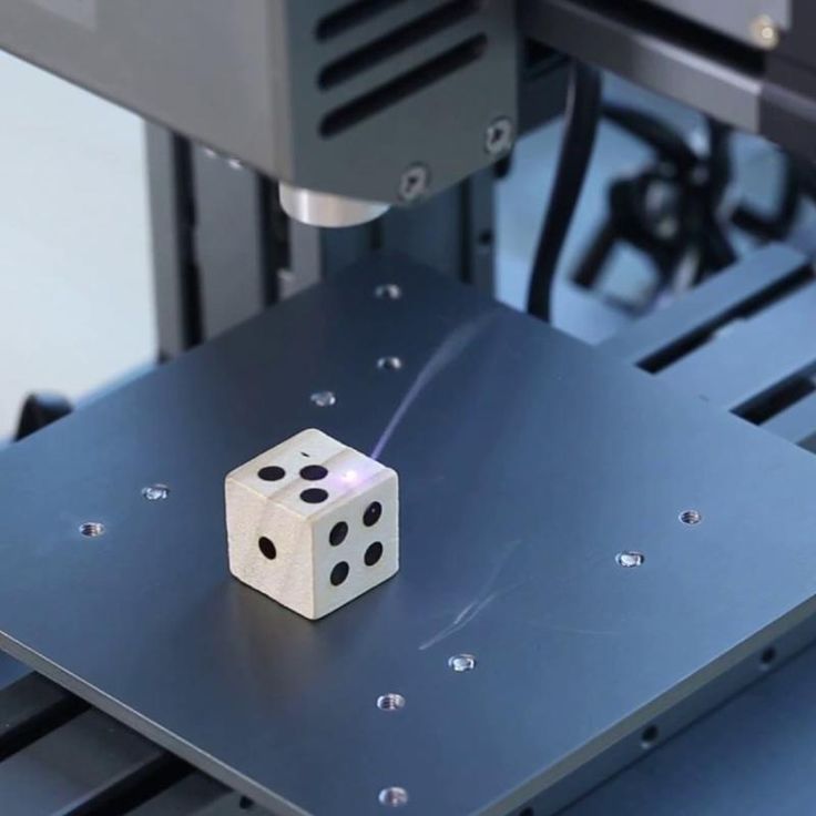 This command can be inserted several times, but keep in mind: each layer change adds 1-2 minutes to the total print time and requires your active actions.
End
All slicers at the end of printing leave standard commands: raising the nozzle, turning off the heaters and blowing. But if several models are printed one after another, then it will take a lot of time to reheat the nozzle and table. To prevent the printer from turning off the heat, you must remove the M104 S0 command from the “Final G-code” window. You can also increase the convenience of working with a 3D printer by adding a macro to play a sound signal at the end of printing.
Sound alert
To play the end-of-print melody, you must add one or more M300 commands after the standard commands in the End G-code window. For example, you can insert three consecutive beeps:
M300 S1000 P100
M300 S1000 P100
M300 S1000 P100
Or the opening theme from Mario:
M300 S2637 P150
M300 S2637 P150
M300 S0 P75
M300 S2637 P300
M300 S2093 P150
M300 S2637 P300
M300 S3135 P300
M300 S0 P300
M300 S1567 P300
Star Wars:
M300 S1396 P166
M300 S1396 P166
M300 S1396 P166
M300 S932 P1000
M300 S2793 P1000
M300 S2489 P166
M300 S2349 P166
M300 S2093 P166
M300 S1864 P1000
The Simpsons:
M300 S2093 P562
M300 S2637 P375
M300 S2959 P375
M300 S1760 P187
M300 S3135 P562
M300 S2637 P375
M300 S2093 P375
M300 S880 P187
M300 S1479 P187
M300 S1479 P187
M300 S1479 P187
M300 S1567 P750
And even music from Indiana Jones:
M300 S1318 P240
M300 S0 P120
M300 S1396 P120
M300 S1567 P120
M300 S0 P120
M300 S2093 P960
M300 S0 P180
M300 S1174 P240
M300 S0 P120
M300 S1318 P120
M300 S1396 P960
M300 S0 P360
M300 S1567 P240
M300 S0 P120
The scope for imagination is huge, so you can come up with your own composition and record it in the form of M300 command sequences.![]()
Interesting fact: the author of the Make Anything channel played a tune from the Nintendo service using a 3D printer. The highlight of this video is the use of not only the speaker on the printer board, but also the sound of motors and even a kind of maracas printed on the same printer.
Special
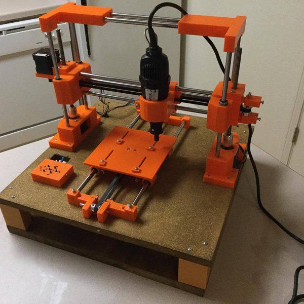
This group of macros includes exceptional macros that are often inapplicable, but in some situations they can greatly simplify printing. For example, a macro for sequential printing of models. That is, the printer prints a model, then either the printer itself or a person separates the part from the table, and the printer starts printing the next model. This process has many limitations and is extremely difficult to customize specifically for your printer. An example of the execution of this idea can be seen in this video.
Nozzle cleaning
If the nozzle gets dirty quickly and you are tired of cleaning it, and you don’t have a silicone cover for the hotend, then you can clean the nozzle before each print using a metal brush. To do this, you need to fix a metal brush in the far corner of the table, and add the following lines to the initial G-code, after the nozzle heating commands:
G28; Movement to the origin
G90; change to absolute coordinate system
G0Z10; raising the nozzle to “Cleaning Height”
G0 Xnnn Ynnn; moving to the far edge of the brush
G0 X(nnn-10) Ynnn; moving to the near edge of the brush
G0 Xnnn Ymmm
G0 X(nnn-10) Ynnn
G0 Xnnn Ymmm
G0 X(nnn-10) Ynnn
G0 Xnnn Ymmm
G0 X(nnn-10) Ynnn
G28; return to origin
Here, instead of Xnnn and Ynnn, there should be the coordinates at which the far edge of the brush is located. For example, for a 200x200mm table, the movement commands would look like this:
G0 X195 Y195
G0 X185 Y195
The height at which the nozzle will be located must be selected experimentally. It is desirable that the bristles of the brush completely cover the nozzle, but do not interfere with its movement.
Attention: the brush must be firmly fixed, otherwise, when it is separated from the table, it can block the movement mechanics and break the motors!
Macros in Cura
Relatively recently, the Cura slicer has acquired the ability to edit Gcode in the program itself. A distinctive advantage of this method is the feedback between the slicer and this function, which allows, for example, to display the remaining print time directly on the printer screen.
To start working with macros, you need to open the post-processing window. To do this, select the “extensions” tab in the toolbar, then “post-processing” and click “Change G-code”.
A post-processing window will open in front of you. In the left half there will be a list of plugins, on the right the settings of the selected plugin. Working with multiple plugins is similar to working with layers in Photoshop. Scripts will edit the Gcode file in order, meaning a script can affect upstream scripts, but not vice versa.
The following is a list of scripts and their brief description:
-
Change at Z
This script allows you to change the speed, temperature, flow and blowing power at a certain height. The values are applied to all subsequent layers. You can also choose to display changes on the printer screen. Basically the script is used to print test models.
-
color mix
This script is for mixing extruders (eg A10M from Geeetech). Unlike just two-color printing, this extruder can mix two plastics, which allows you to create transitional shades.
-
Create Thumbnail
Create icons for Ultimaker Format Package (.ufp) files. Used when implementing a slicer in Octoprint.
The name speaks for itself: displaying the file name and layer number on the screen.
Displaying the remaining print time on the printer screen
-
Filament Change
Automate the Gcode editing process for changing filament.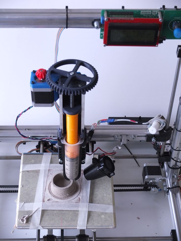
It is an analogue of the Gcode insertion windows when changing the layer in PrusaSlicer
-
Retract Continue
Allows you to add recoil during nozzle movement between parts of the model
-
Search and Replace
Removes the specified characters and replaces them. If replaced with a space character, then this script simply removes the specified characters
-
time lapse
This script helps in creating high-quality time-lapses using the camera. At each layer, the printer will move the carriage to the side and send a command that can activate the camera.
If your printer has the ability to build a table height map, then this script will replace the repeated height measurement with the result of previous measurements.
The most commonly used and useful plugins are Change At Z and Search and Replace. They cover 80% of all required changes in Gcode. Therefore, even if you are not going to use them in the near future, it is still better to study them at least at a superficial level.
Basic command tables
When servicing the printer, the final step in checking and setting up is to self-diagnose the printer and check it in operation. But not all actions can be done from the printer menu. For convenience, we have collected all the necessary commands in one small table that you can quickly open and use.
| Team | Options | Description |
|---|---|---|
| G28 | X-axis X | Moving to zero coordinates. If parameters are specified, then parking only along the specified axes |
| M92 | X - value on X | Set the number of steps per millimeter for each specified motor |
| M303 | S - temperature | PID autotuning command. The more cycles, the higher the accuracy |
| M301 | H - heater number | Set the value of PID parameters for a given heater |
| M112 | - | Emergency stop: |
 0
0 WARNING! If the printer gives an extruder or bed heating error, then the M112 command may not fix the problem, as this error often occurs when the transistors / relays are “jammed” or shorted! It is better to immediately turn off the power to the printer, and then find out the cause of the error.
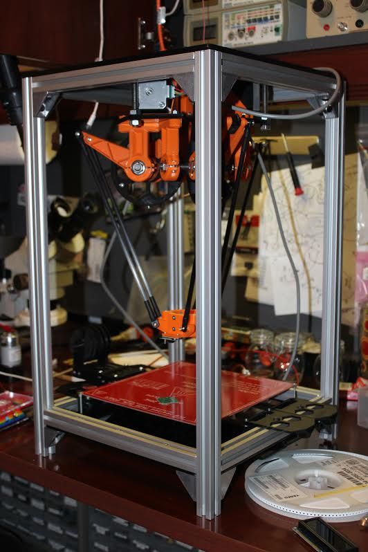
Modix Large 3D Printers - Modix Large 3D Printers
Modix Large 3D Printer is the
your best next 3D printer!
- Two-headed IDEX printing-novelty
- components of premium-class
- Supermarial design
- Multiple
- High resolution
are delivered in the form of sets for independent assembly:
- Manage your configuration
- Self service
- Easy to upgrade
- Within your budget
- Compact package
Modix Large 3D Printer is your next best 3D printer!
- Premium Components
- Heavy Duty
- Multiple Options
- High Resolution
1072
- Manage your configuration
- Self service
- Easy to upgrade
- Within your budget
- Compact package
New generation 4 November 22
Modix is proud to announce the release of its new unified 3D printing platform called Generation 4 with IDEX dual head technology. Modix continues its path to market leadership by integrating cutting edge technology while maintaining outstanding value for money.
Generation 4 upgrades the Modix offering with new features such as printing models with internal geometry, faster print speeds, faster post-processing times and higher reliability.
Find out more about the fourth generation of Modix - click here
IDEX allows you to print models with internal geometry, provides high quality surface finish while reducing post-processing time.
View details
The Griffin printhead delivers high print quality, impact resistance, easy replacement and higher print temperatures than ever before.
Learn more
A set of reliability sensors designed to save time on print jobs. It can detect filament runout, under extrusion and clogging.
Learn more
Complete set of automatic calibration tools including: bed tilt calibration, bed leveling, gantry leveling and Z-offset calibration.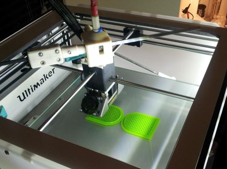
Learn more
Don't limit your future ideas, get a bigger printer today!
Premium Components
ControllerUK
Extruder Sweden
U.S. Movement
Drivers of the German step engine
Power voltage
Taiwan
Alignment of the bed South Korea
Printed Taiwan Rifle Rifles 9000 9000 9000 9000 9000 9000 9000 9000 9000 9000 9000 9000 9000 9000 9000 9000 9000 9000 Germany
Professional Features
For more information about our large 3D printer technology, please CLICK HERE
IDEX
Double independent extruders
touch screen
7-inch sensor screen and web interface for remote monitoring
Duet Controller
Advanced Electronics with a control system
00 your health with a set of charcoal and HEPA filters.
(Optional)
Shielded wires
IGUS signal cables for greater reliability.
Magnetic bed
Easily remove printed objects when finished.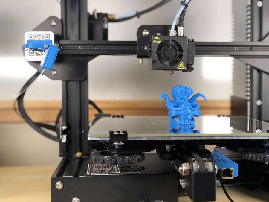
(Optional).
Fault Detector
Detect hardware failures and prevent failures.
High Quality
One of the most significant advantages of Modix large-scale 3D printers is the carefully selected premium components, each of which contributes to high quality printing. These components include: Bondtech Extruder (Sweden Made), E3D Nozzles (UK Made), DUET3D Controller (UK Made), Trinamic Motor Drivers (German Made), IGUS Shielded Signal and Power Wires (German Made), Alcoa Cast Aluminum Plate Mic-6 (made in USA), Meanwell power supply (made in Taiwan) and more. Nearly every component in our large format 3D printers contributes to print quality and reliability, which is why we choose the highest component standards, even for the smallest parts, such as aircraft grade power adapters, durable castors, fiberglass reinforced belts, etc.
Heavy Duty
A key design factor in our large scale printers is the heavy duty design. Because our large format 3D printers are supplied as DIY kits, we place great emphasis on ensuring that the end user achieves the highest levels of accuracy and consistent calibration. This includes a very detailed online build guide with 3D models that can be rotated and scaled, several detailed video tutorials for each step, and more. In addition, we provide our clients with calibration methods and tools that help make this process as successful and as smooth as possible.
IDEX Dual Extrusion
IDEX's dual print head technology allows internal geometry to be printed using a dissolvable support filament. Once completed, you can dissolve the support material and enjoy high-quality results without the tedious manual removal of the support. With tear-off support, you can quickly remove the support immediately after printing is complete. In addition, you can enjoy the smooth surface of the bottom surfaces. With a secondary support thread, you can maintain zero distance between dense support layers and the model itself, so the surface will be much smoother than when printing support from the same material.
Customizable Platform
Modularity is our flagship concept. In fact, the Modix brand is called "modular technology". At Modix, we're constantly making new optional add-ons available to easily add to your printer, including air filters, multiple printhead configurations, and more. There are several additional setup guides on our customer's online services portal.
Wide Choice
Our Griffin printhead offers a wide range of nozzle and heater block configurations. Modix offers the three heat block sizes: the default high performance Griffin hot end, the short E3D-V6 hot end for detailed fine printing, and the E3D Super Volcano for rough and fast 3D projects. Each of the thermoblocks has several options for nozzles, some of them are offered as part of our set. Other materials can be purchased directly from the E3D online store, such as high-quality hardened steel nozzles that can print with abrasive filaments (such as filament containing carbon fiber).
Open Architecture
Our clients are not locked out! Modix believes in freedom of choice, especially for passionate innovators. Users can select filament from any source and use a variety of modeling and slicing software solutions to suit their needs. We recommend the Simplify3D slicing software, but recognize that users may have other software preferences such as Cura and Slic3r. They also work great and are compatible with our larger 3D printers. Our customers are provided with print profiles for each of these slicing software packages.
Self Assembly
Self assembly is the preferred method of purchasing a 3D printer for many professionals for several reasons. Practical approach - you build your own machine to better understand the motion system, print head and calibration. You will gain invaluable insight into how to maintain your printer and how to upgrade it in the future. Just like your PC's operating system, Modix large format 3D printers are specifically designed to be customized and adapted to your specific needs.
Future Ready
We are constantly developing and innovating, so when you buy a Modix 3D printer, you are actually investing in a platform that can be upgraded from time to time. Owners of earlier versions are now offered the benefits of our latest version (Generation 4.0). This alone improves the long-term sustainable use of the printer and increases your return on investment.
Big Benefits of 9009 3D Printer7
Experienced 3D printer users who already own one or more small desktop 3D printers and are now looking to expand their printing capabilities should consider the following unique advantages of large format 3D printers:
1. Printing large, one-piece 3D models makes they are stronger.
2. Printing models as one part also saves post-processing time. There is no need to fit smaller pieces together or try to hide a seam.
3. Another unique advantage of the large printbeds is the fact that you can print multiple small items in one batch. Batch production can be set up to complete one object before starting another ("sequential printing") for greater reliability.
Premium Support since 2015
Modix prides itself on its prompt and professional support!
We believe that any product is only as good as its service, and since the beginning in 2015 we have worked hard to maintain this concept. If received, help requests are cleared daily. If necessary, videoconferencing sessions are scheduled to better understand the ground situation. This saves time both in understanding the problem and in quickly finding a solution.
Reviews
Mr. Brian Grimm
Engineering Garage USA
BIG-60 B3
Mr. James Lowick
Australia
BIG-60 B3
MR. Jeff Raymond
Real Martian USA
BIG-120V3
Frank 3D Printing
Lab USA
BIG-60 V3 (Open Mode)
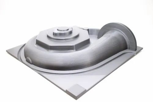
Use Cases
Canon Restoration 1.6 meters
Made in Ireland
Robot housing parts
Made in Germany
Motorcycle engine cover
Made in Czech Republic
Bronze cast
Made in Turkey
Goodyear Farm Tire
Made in USA
Cutter cover
Made in Israel
PCB Maker
Made in France
Prosthesis cover for high legs
Made in Portugal
trusted By
Aerospace
Automotive
Protection
Production
Production
Educational
Get an overview of our new product:
The product overview includes a detailed technical review, updated specifications, and answers to frequently asked questions, including how to print at high temperature, software comparability, and more.