Sense 3d scanner problems
All Issues that May Be Encountered and the Solution to Solve them
The 3D scanning is a now widespread technique in almost all industrial and commercial sectors, but also in art, architecture, and in the medical sector.
The merit of this widespread diffusion lies in the fact that 3D scanners are increasingly easier to use even for non-expert users.
Furthermore, 3D scanning technologies allow to speed up most of the production activities and make possible previously unthinkable processes or interventions.
Nevertheless, some problems can always occur during the 3D scanning phase , which can be overcome with easy tricks.
In this article we want to examine the various difficulties that can arise during a 3D scanning session and reveal the tricks and techniques to solve them, making 3D scanning possible for any type of application.
HOW TO PERFORM A 3D SCAN IN ANY SITUATION
If you have ever tried your hand at a 3D scan using optical 3D scanners, you will surely have found yourself faced with some questions including:
- How to scan glossy or black surfaces ?
- How to scan cavities ?
- How to scan thin objects like foil?
- How to behave in case of loss of alignment with both markers and without markers?
- How to exclude some areas of the scene from 3D scanning?
- How to automatically or manually align two 3D scans of different parts of the same piece?
In all these situations it is still possible to perform a quality 3D scan but with due precautions, techniques and tools. Let's analyze each point individually.
1. 3D SCANNING OF GLOSSY OR BLACK SURFACES
With shiny or black or shiny and black surfaces, most optical 3D scanners have difficulty detecting 3D geometry correctly, as light is reflected excessively from surfaces or completely absorbed.
What can therefore occur is a non-acquisition or a partial acquisition of the objects.
To overcome this difficulty, first of all professional and advanced 3D scanners can be used, which allow manual and / or automatic adjustment of some optical 3D scanning parameters such as exposure .
The 3D scanners that allow this adjustment can be either laser 3D scanners , such as Shining 3D's FreeScan series , or structured light 3D scanners , such as Shining 3D's EinScan Pro series , or with new technological advances, it is It is possible to have hybrid 3D scanners, which combine laser and structured light 3D scanning technologies in a single tool, such as the Shining 3D EinScan HX and H series 3D scanners .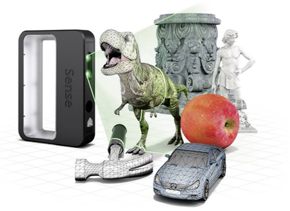
In general, however, 3D laser scanners are often the most suitable for surfaces with different optical characteristics.
Some 3D scanners are able to self-adjust the exposure in real time according to the surface to be scanned; others allow manual adjustment, which in this case must be low for light surfaces and high for dark surfaces.
If there are both light and dark surfaces in an object at the same time, automatic exposure is the best solution.
In those cases in which the 3D scanner is not equipped with adjustable optical parameters, or if even by adjusting the parameters it is not possible to acquire the surface, it will be possible to perform the 3D scan by opacification with special powders, some of which are evanescent and do not leave no trace on the surfaces. One such product is Aesub Blue spray.
2. 3D SCANNING OF OBJECTS WITH CAVITIES
In the event that the objects to be scanned have holes and cavities, it will not always be possible to 3D scan even the cavities themselves, since normally only the surfaces that the laser or structured light of the 3D scanner can reach are scannable.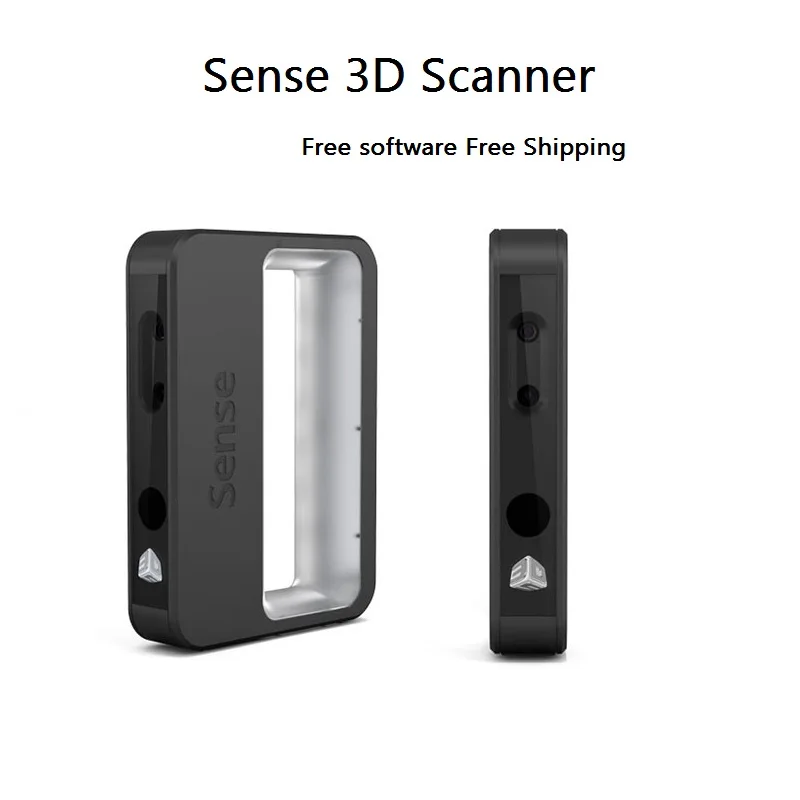
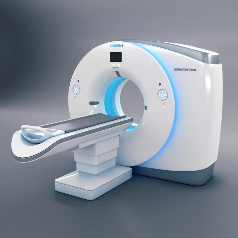
To scan cavities totally internal to objects, 3D scanning can be replaced with computed tomography (CT), if instead the cavities have an outlet on the external surface, you can try to scan them as far as the light reaches.
Some 3D laser scanners, such as Shining 3D's FreeScan X7, are equipped with a special laser blade capable of going deeper into cavities and through which it is also possible to acquire some narrow holes.
3. 3D SCANNING OF THIN OBJECTS
In the case of thin objects such as foils, the difficulty in scanning lies in the fact that around the edges of the thin wall the 3D scan can be very noisy or even the edges may not be scanned at all. This is due to the fact that light reflects unpredictably around a very thin edge, resulting in clusters, holes and errors.
In this case, the adjustment of the optical scanning parameters and the possibility of using a 3D laser scanner can overcome this drawback or at least limit it.
In general we can say that the more professional and metrological the 3D laser scanner is, the more successful the 3D scanning of thin objects can be.
However, even in the event of errors or clusters near the edges, the exact geometry of the sheet can always be reconstructed thanks to the best performing 3D modeling and mesh editing software, which can be combined with any 3D scanner.
4. WHAT TO DO IN CASE OF MISALIGNMENT DURING A 3D SCAN
If you use automatic portable or even tabletop 3D scanners, 3D scanning takes place in real time through the automatic alignment of each scan frame on the previous one, using physical markers, or using geometric or color characteristics.
In the event that real-time alignment is momentarily lost during 3D scanning, the 3D scanner will either no longer acquire 3D data, or will misalign it.
In both cases there is an effective solution to remedy the problem.
In the event of temporary loss of alignment in the presence of markers, simply reposition the 3D scanner so that it will re-acquire a certain number of previously acquired markers. In this case the alignment will be restored and the 3D scanning can continue without problems. Generally, in order not to lose alignment, it is necessary to position the markers so that there are always at least 4 markers in common between one 3D scan frame and the next.
In case of loss of alignment in the absence of markers, the 3D scanner must be repositioned on a previously acquired geometry, so that it can be recognized and the alignment restored. If this fails automatically, in some 3D scanners it is possible to select an option through which the frame from which to restart can be selected to regenerate the alignment.
Generally, in order not to lose alignment in the absence of markers, it is necessary to move the 3D scanner so that there is always a sufficient overlap area between one 3D scan frame and the next.
In any case, if misaligned or misaligned frames are recorded during the misalignment, with most 3D scanners you can select and delete them, so that the 3D scanning continues without problems.
5. 3D SCANNING EXCLUDING SOME AREAS OF THE SCENE
In case you want to exclude a part of the scene from 3D scanning, such as when you want to eliminate the table on which an object is placed, some 3D scanners and some 3D software allow you to do this automatically by defining work plans that delimit the region of space that you want to scan. These cutting planes are very useful for isolating the objects you want to view within the 3D scan.
6. THE ALIGNMENT OF DIFFERENT 3D SCANS OF THE SAME OBJECT
In some situations it may be useful to scan the same object from two different perspectives and then combine the two 3D scans to form a single 3D model. In this case the alignment can be done either by target or by geometric characteristics.
This operation requires the use of software for mesh registration and can be performed by selecting any targets in common on the two parts of the object, or parts with overlapping geometry and aligning them using best fit algorithms.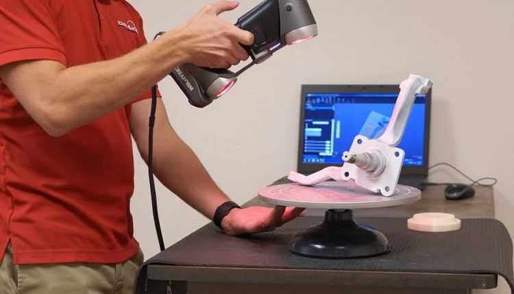
XYZ hand held 3d scanner troubleshooting - Scanning - Talk Manufacturing
Tim_Jason_Sparr
#1
so i just got my scanner a new imac and run and installed parallels and have windows 10 running smoothly on my mac … installed the intel real sense sdk as part of the xyz packaged software and i keep getting a error 5041 device not found , please try again message , i have updated the software and controlled all drive updates for the usb 3 ports , its still not working , can any one help …
1 Like
Xeno
#2
Did you assign the right USB port to Parallels ?,
when you plug in your device, Parallels should ask where you want the USB device connected to, Win or OSX.
Tim_Jason_Sparr
#3
yes i did … im just wondering if perhaps the scanner has an internal fault as the button on the scanner lights up … i shall look into trying the scanner on a up to date pc ( local pc outlet ) … if it gives the same error perhaps its a hardware problem … will let hou know … Thanks for you help …
micahwelner
#4
@Tim_Jason_Sparr did you ever figure this out! i was about to purchase the XYZ before i realized it wasn’t mac friendly. then i remember parallels which i already had a copy of. did you ever get it to work through parallels? hope so! let me know thanks happy holidays
Tim_Jason_Sparr
#5
I haven’t managed yet to run it through parallels . I went to a PC shop and they had it up and running on a new pc with the latest intel chip . I have a new iMac ( literally a month old) and the technician at the pc shop thought there may be an issue with the type of intel chipset that mac uses . its all down to the intel real sense camera that the device uses and perhaps also usb power issues . It may be a graphics card issue too . For now if you haven’t a pc I’m not sure if its going to work . Which is a shame , would be nice if xyz-printing had a wiki or its own help page on this considering the 3d printer (junior) runs ok on my iMac , suppose its about licensing with intel or microsoft or something … anyone else manage to solve this …please help out as i have a scanner doing nothing … would have been nice to get it up and running for the holidays …
pomusa
#6
I bought this item recently and it was missing the SD card. I was wondering if you still have the driver for Windows 10?
thanks
Boon
Tim_Jason_Sparr
#7
i will take a look … its now still in its box … will try to get it running this weekend
PAK5000
#8
I get the same error on a windows 10 pc. and there was no SD card in the box. and i can’t find the driver on their site. also, on the first machine i installed this on, it never prompted for a driver. the scan quality was just very low and compared to the how to videos, it took me a lot longer to get a scan. then the scan button would not enable. the button on the scanner lit up but did nothing. that was in xyz handy. i tried 3d sense. as soon as i hit the scan button the app crashed. so tech support said try another pc. xyzhandy wants a mystery driver and 3dsense does not detect a scanner. i think the scanner went bad and am working with them to get a replacement.
updating all the windows drivers, the intel realsense and graphic card drivers, did get it working for a short time on the original pc. but there was no SD card. and the apps never prompted for a driver. i think it is just a bad scanner they need to replace.
Measuring Large Metal Products: The
3D Scanner Solving Your ProblemsLincoln Electric Additive Solutions provides a full range of services for the manufacture and supply of large metal products for various industries - electric power, oil and gas, transportation, aerospace, defense, as well as heavy industries .
Lincoln Electric pioneered large-scale 3D printing of prototypes, serial parts, spare parts and tooling in steels, stainless steels, invars and nickel alloys. The additive manufacturing division of this multinational company knows first-hand how to make very large products - up to several meters in size and weighing up to several thousand kilograms.
Lincoln Electric - Leading the Way in Advanced Technology
Lincoln Electric has always prided itself on using the latest manufacturing methods to gain competitive advantage. That is why the company was one of the first to develop and implement 3D printing technologies for the rapid production of high-quality large-sized parts, many of which have complex geometries.
In the additive manufacturing of metal objects, exact dimensions play a particularly important role. Because large, complex parts are being printed, traditional quality control tools (such as coordinate measuring machines or measuring arms) do not meet Lincoln Electric's requirements for speed and measurement versatility.
With the Creaform 3D Scanner, we get our products to market faster because we control part geometry faster.
Mark Douglass, Business Development Manager
Lincoln Electric Additive Solutions
Classic systems, for example, are not suitable for measuring directly on the shop floor. “We make very heavy and large parts,” says Mark Douglass, business development manager for Lincoln Electric Additive Solutions, “and it's important to us that the part doesn't have to be moved as much as possible. We knew that CMMs and measuring arms didn't meet this criteria and started looking for other options. The solution was 3D scanning.”
3D Scanner Implementation Lincoln Electric Additive Solutions uses Creaform 3D measurement solutions to quickly and accurately control the geometry and quality of printed metal products. Designers and quality control professionals create 3D surface models of AM parts and compare them to the original CAD models.
Lincoln Electric additive manufacturing engineer Amanda Dodge notes, “The parts we make often have many unique elements, and it's important that each one is in the right place. The 3D scanner helps to capture all the complex elements we print and check if there are any errors.”
“Operators and engineers were enthusiastic about the new solution. Now we measure parts in just a few minutes,” Mark adds. “Creaform devices are portable and now we can bring them to the details, not the other way around.”
MetraSCAN 3D Complements Large Parts Additive Manufacturing
As Lincoln Electric Additive Solutions grew, so did the size of its products. The company needed to find a way to quickly and accurately measure large parts without moving them. For this purpose, the Creaform MetraSCAN 3D 3D scanner was selected, the fastest and most accurate portable 3D scanner for production environments.
“MetraSCAN 3D is a great solution because it provides non-contact measurements. Position marks are not required. We can scan products and check their geometry and quality at any stage of production - even during 3D printing, when the temperature of the parts is very high, - Brad Barnhart, an additive manufacturing engineer, shares his impressions. “3D scanning helps measure parts much faster because technicians don’t have to wait for them to cool down.”
Amanda Dodge noted that parts do not need to be cleaned prior to 3D scanning and this also saves a lot of time.
3D Scanning is a Powerful Growth Driver for Your Business
Mark Douglass believes that the use of Creaform 3D scanning systems has greatly contributed to the growth of the business. “We can quickly check the quality of all printed parts and are now absolutely confident that every piece produced meets the customer's requirements,” Mark adds. “We also get our products to market faster because we can control part geometry faster.”
According to Lincoln Electric Additive Solutions, additive manufacturing is rapidly gaining popularity and plays a significant role in the company's long-term strategy. “We continue to grow and Creaform 3D scanners will continue to be an integral part of our manufacturing process.”
Author Sergey Dumilin
Source
Tags:
Lincoln Electric Additive Solutions, large-format 3D printing of prototypes, 3D printing technologies, Creaform 3 measurements, 3D scanner in production MetraSCAN 3D, additive manufacturing, 3D scanning
What determines the accuracy of 3D scanning
Speaking about the accuracy of a 3D scanner, they usually mean the level of compliance of the obtained three-dimensional model with the real characteristics of the sample.
This parameter defines the 3D scanner error or the interval within which the comparison results can vary.
The accuracy of a 3D scanner depends not only on the hardware, that is, on the device’s own characteristics, but also on a number of other factors, in particular, accuracy is affected by:
- object size: 3d scanning of large objects is performed in parts, and stitching increases the error;
- correct choice of lenses;
- correct scanner settings;
- correct preparation of the object for scanning;
- subjective factors during scanning: surface vibrations, lighting.
The same scanner can give different accuracy values depending on the subject being scanned and the skill of the performer. That is why many scanner manufacturers avoid specifying accuracy in device specifications, replacing it with other, more objective parameters (see Table 1), such as resolution. Resolution and accuracy are different concepts, although higher resolution does increase accuracy. The manufacturer's accuracy specification usually corresponds to an ideal object under ideal scanning conditions (see Table 2).
Table 1. Characteristic features of 3D scanners
| Characteristic | Description | | The smallest distance between scanned points in mm. | Determined by the size of the scanned area, which characterizes the resolution of cameras and the principle of operation of the scanner. To improve accuracy, the resolution of the scanner should be less than 1/2 the size of the smallest part to be examined or the minimum size of the product. | |
| Detail | The size of the object in mm, the shape of which can be recognized by the scanner. Standard value for 3D scanner: 1 mm. | Scanners from different manufacturers have different detail values.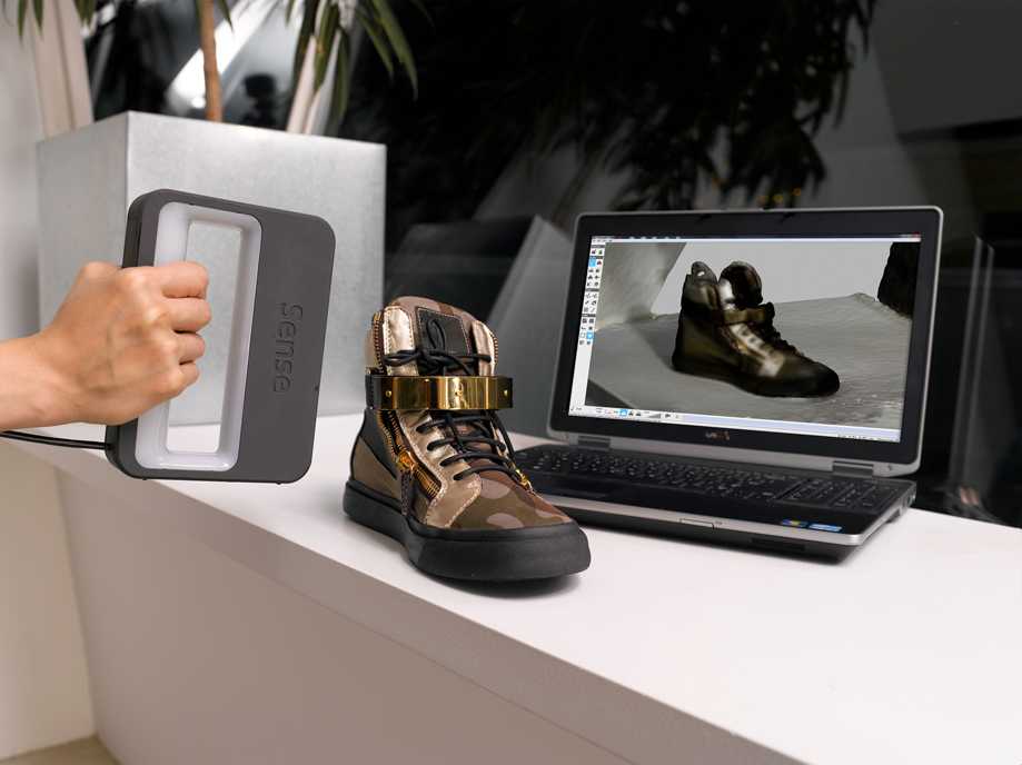 Handheld scanners tend to have finer detail values than fixed scanners. Can be set by repeated scans of the given object under exactly the same conditions by comparing with the first result. Handheld scanners tend to have finer detail values than fixed scanners. Can be set by repeated scans of the given object under exactly the same conditions by comparing with the first result. | Depends on several different factors. For example, surface quality (smoothness/roughness, unevenness and inhomogeneity of the surface) of the scanned object, scanning direction, camera positions (relative to the object and each other), object illumination, etc. | |
| measurement error. | Includes both random and systematic components. |
Accuracy tables are usually written for ideal objects under ideal conditions - a hard smooth product scanned at a constant temperature, etc. Any deviation from the reference conditions affects the resulting accuracy value. The table shows the main parameters that affect the accuracy of 3D scanning.
Table 2 Causes of Loss of Accuracy in 3D Scanning
| Ideal Conditions | Conditions, causing difficulties | The result of work in imperfect conditions |
| TIRIENT OFFICE 90 | Parts of the object scanned from different angles are distorted.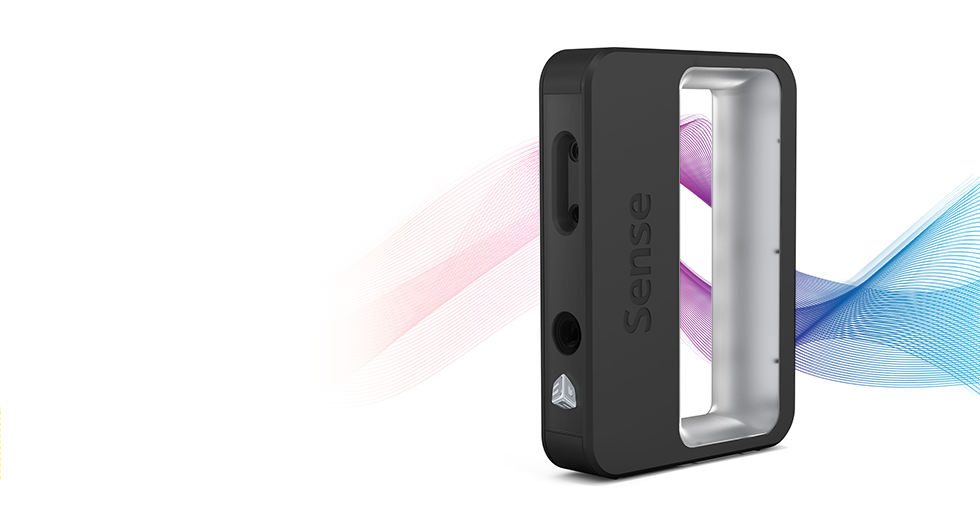 There are problems when combining parts into a single product There are problems when combining parts into a single product | |
| Statical object | Movement of the object relative to the scanner during scanning | Any movement leads to a distortion of the result and deterioration of detail |
| Light object | Dark Object | Most of the scanners not scans black objects, in the 3D model there will be holes in these places, their preliminary matting is required |
| Matte object | Brilliant or translucent object | in 3D models in these places will be holes, their preliminary matting |
| Smooth object | The presence of sharp ribs | The sharp edges are slightly softened, they are slightly softened, it is desirable to observe the rules of relative positioning of the scanner and sharp edges |
| Part without holes | Product with edges of sheet material | The edge of a thin sheet in 3D data always breaks before reaching the real boundary of the object |
| Good geometric features of the object | 9001 Separate fragments cannot be qualitatively combined, accuracy becomes uncontrollable without the use of markers | |
| 0100 | Large or long object, need to scan in fragments | Errors appear when combining fragments |
| Object is scanned perpendicular to the surface | Scanned “at an angle” | Decreased accuracy. |
| Scanner warmed up to operating temperature and then calibrated | 3D scanner not warmed up to acceptable operating temperature | Measurements knowingly contain errors |
| The calibration field was measured at the current temperature | Scanning is carried out in conditions of irregular temperature | The scale of the result will differ from the real object |
| The lighting does not interfere with the process | Bright directional ambient light | increased noise level in the data or the inability to work |
| The cells are located at the recommended distance of | Cams shifted for scanning depressions and undercurrents | In the data of |
| The temperature in the room is stable stable | Indoor temperature changes according to outside weather conditions | Change of product parameters depending on outside temperature |
Effect of temperature on accuracy
Most substances expand when heated. The effect of thermal expansion reduces the accuracy of 3D scanning. In an unprepared room, the temperature can fluctuate within 10 or more degrees. At the same time, the sizes of objects, depending on the material of their execution, will change up or down. Thus, for some objects there is no significant value of more than 0.1-0.2 mm/meter accuracy.
Accuracy when combining scans of an object
When scanning an object from different angles, it becomes difficult to process further results, since errors arise when combining different fragments. Several matching technologies are used:
1. Matching by surface geometric features. The accuracy of this technology is the highest, but only if the object has a sufficient number of characteristic features. If the entire object is placed in the scan area, the drop in accuracy during alignment is insignificant. If the geometric features are not enough (scanning large smooth objects), other alignment technologies are used.
2. Alignment by markers. Before the scanning process, the model is prepared for work - in an arbitrary chaotic manner, markers of a contrasting (in relation to the object) color are glued evenly over the surface. The scanner automatically reads the coordinates with a marker and combines the fragments.
3. Marker alignment using a photogrammetric system. For large objects, a technology is used when marker coordinates are estimated in advance using a photogrammetric system, which ensures high accuracy.
Application examples and accuracy requirements
Perfect accuracy requires expensive equipment. However, not all products require high accuracy values. Therefore, it is necessary to understand whether it is worth investing in such parameters.
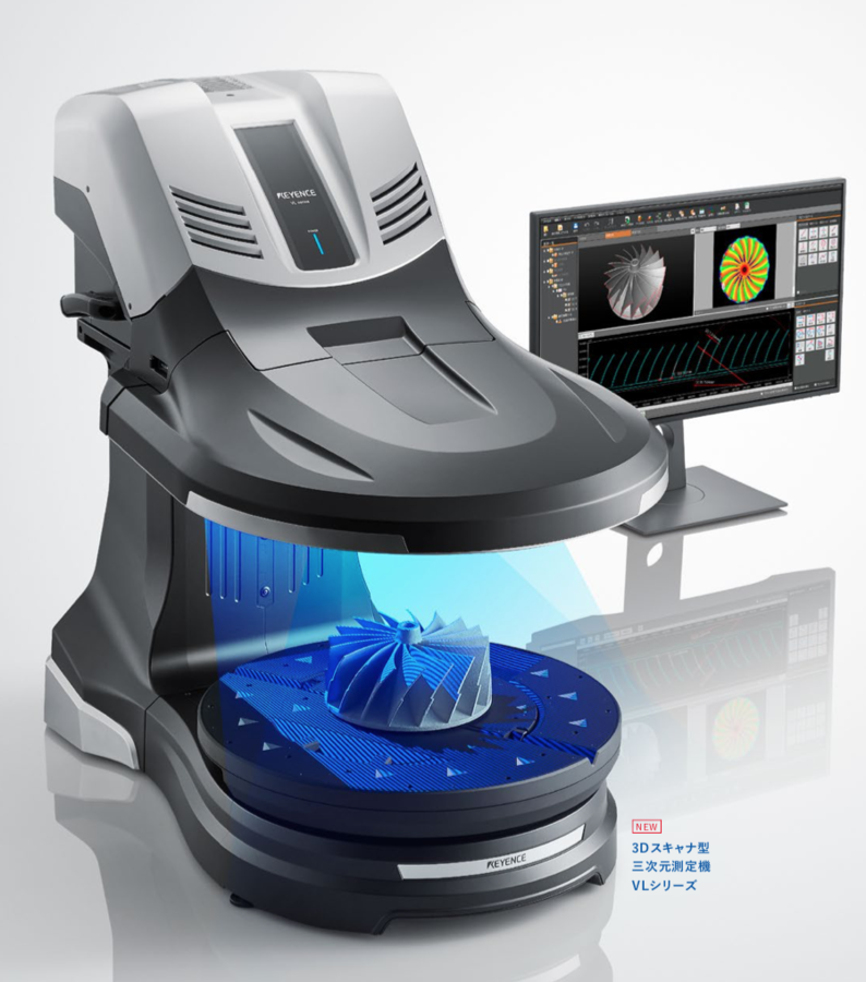
For example, the high precision requirement is used in applications such as controlling the fabrication of turbine blades or artificial heart valves.
In general, when scanning most other products, an accuracy of 0. 1% of the measured length is sufficient. When scanning a car bumper, that is, a part connected to other parts, 1 mm or less is considered the minimum sufficient accuracy. In most design and creative tasks, for example, when scanning plaster molds, sculptures and jewelry, there are elementary requirements for accuracy, first of all, it is necessary to reduce noise, improve detail, and work out the surface of the object as carefully as possible.
Table 3. Examples of tasks and requirements for accuracy
| Task | Requirements |
| BUSTIC SHIPS, EVERY OF THE PAPE , a statue. Reduced copies of the sculptures are supposed to be made using CNC machines or printed on a 3D printer. | In this case, there is no need for high precision. It is of great importance to obtain a visually identical result, i. e. high detail, minimum noise level is required. The end result is a finished STL file suitable for further work with the manufacturer. e. high detail, minimum noise level is required. The end result is a finished STL file suitable for further work with the manufacturer. |
| Scanning a bicycle fork, pedal, frame. Scan results will be the basis for modeling another fork, pedal, frame. | The surfaces of the old fork and pedal are not of interest. Attachment points, landings and connection lines are of particular importance. Accuracy of the order of 0.5 mm is required at the specified locations. |
| Scanning a glass bottle. Based on the result, a new form will be created. | Requirements for accuracy are minimal. The neck shape and thread elements are taken from the CAD model. The shape of the vessel itself will be recreated. T.K. the shape is smooth, the values of the noise level and detail are not significant. Precision values are not important. |
Accuracy in the development of a solid 3D model
From the scanner we get a raw file (point cloud or polygonal model), which we then bring to a solid 3D model in a CAD program, for example, SoliDWorks.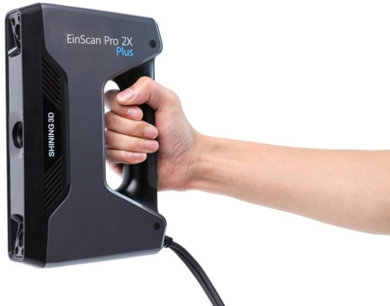
When modeling objects based on the received data, the dimensions are usually rounded to integer values. For example, when scanning, we received an aluminum case with dimensions of 327.18 x 240.05 x 194.76 mm - in this case, the designer will almost always adjust the dimensions in the work to 327.00 x 240.00 x 195.00 mm.
In addition, the shape of new CAD objects, built according to STL data from the scanner, may differ significantly from the actual surface, since the functions of mathematical approximation, smoothing and surface simplification are used when it is built using CAD packages.
P.S.
For applications where accuracy is critical, additional measuring systems are often used in addition to the scanner. It must be understood that although a 3D scanner has outstanding technical characteristics, it is still not a measuring device. In this regard, before launching a part into mass production, it is necessary to make a trial series in order to check the result in work and correct possible shortcomings.