Reuleaux triangle 3d print
▷ reuleaux triangle 3d models 【 STLFinder 】
Reuleaux triangle
grabcad
Reuleaux triangle
Reuleaux triangle
thingiverse
Just a normal Reuleaux triangle/
Reuleaux Triangle
cults3d
This is a Reuleaux triangle which can roll on its side like a circle. ...Enjoy!
Reuleaux Triangle
pinshape
Summary This is a Reuleaux triangle which can roll on its side like a circle. ...Enjoy!
Reuleaux Triangle
thingiverse
The reuleaux triangle is a shape of constant width. ...You can even roll things on top of it, or spin it around in a square frame! More about it here: https://en.wikipedia.org/wiki/Reuleaux_triangle.
Reuleaux Triangle
thingiverse
This is a Reuleaux triangle which can roll on its side like a circle. Enjoy! Please visit my Youtube Channel for more 3D Printing content! ... https://www.youtube.com/channel/UC4ewBPsaamFM9hYYorJLayA
Reuleaux Triangle
thingiverse
A Reuleaux triangle is a constant width curve based on an equilateral triangle.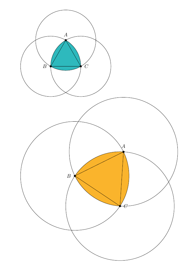 ... It can rotate within the square while maintaining contact with all four sides of the square.
Reuleaux Triangle
thingiverse
This is a reuleaux triangle, which is a shape of constant width. ... +=================================================+ Print Settings Resolution: .1 (doesn't really matter) Shell Thickness: 1.2 Fill Density: 25% (not a big deal) No Support I...
Reuleaux triangle
thingiverse
Reuleaux triangle This week Angus on Makers Muse (1) presented a really interesting shape, that roles like a sphere but was a triangle, cool eh. This really messes with convention, so much so, you really need to try it for yourself. We form the...
Reuleaux triangle
myminifactory
Reference:- MakersMuse YouTube - https://youtu.be/2eUWT9cI23o Wikipedia - https://en.wikipedia.org/wiki/Reuleaux_triangle Leonhard Euler - 1781- Paper on De curvis triangularibus. ... I used Grey PLA from https://rigid.ink but you can use any colour...
Reuleaux Triangle
thingiverse
http://en.wikipedia.org/wiki/Reuleaux_triangle More math about the Reuleaux Triangle (and the site where the cool animated gif that shows the path of the center of rotation is from):http://mathworld.wolfram.com/ReuleauxTriangle.html Instructions Cut...
Reuleaux Triangle
thingiverse
Couldn't find a decent 3D model of Reuleaux triangle (constant radius) available online, or others were modeled incorrectly. Decided to have a go myself. I believe this is a good challenge for modelers. I will use this in a 2 part silicone mold to...
Customizable Reuleaux Triangle Vase
thingiverse
This thing is a spiral reuleaux triangle vase. ...The reuleaux triangle shape does not serve any purpose other than the look. ...This thing is customizable so feel free to change the size, shape, and twist to your desires.
Reuleaux Triangle and Box
thingiverse
The reuleaux triangle is a geometric shape that has an equal diameter throughout. ...This is significant, because this trait is also shared with circles.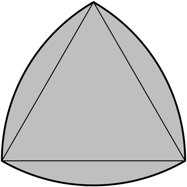 reuleaux triangle width: 40mm Box internal width: 40.05mm (for breathing room) Printing Soon!
Reuleaux Triangle Keyring
thingiverse
Customisable keyring based on a Reuleaux triangle (https://en.wikipedia.org/wiki/Reuleaux_triangle), a shape of constant diameter. Multiple sets of keys can be attached to the different holes if desired. ... I will soon be uploading a version that...
Calibration Reuleaux Triangle
thingiverse
A Reuleaux Triangle for Calibrating your Delta printer. ...Triangle sides are 60mm, circle is 40mm in diameter and height is 5mm
Reuleaux Triangle Engine
thingiverse
. .. triangle between the other two vertices. Because of this, it can be rotated inside a square.
They are named after Franz Reuleaux, a 19th-century German engineer who pioneered the study of machines for translating one type of motion into another
.. triangle between the other two vertices. Because of this, it can be rotated inside a square.
They are named after Franz Reuleaux, a 19th-century German engineer who pioneered the study of machines for translating one type of motion into another
Reuleaux triangle intermittent mechanism
grabcad
I was reading about Reuleaux triangle (constant width) and wanted to do something using this. Then I found a tiny gif (http://imgur.com/gallery/U45Op) that called my attention. The only problem was to find the correct gears, after that it worked...
Reuleaux Triangle Bearing Gears
thingiverse
Based on Reuleaux Triangle bearings and shapes of constant width.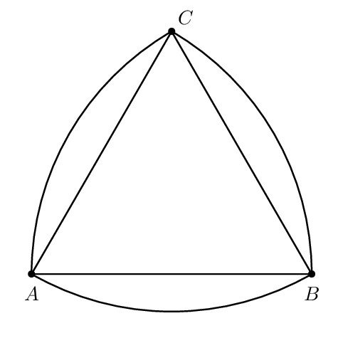 Have fun!
Note: While I have printed these files successfully on my CR-10S with minimal issues, it seems like a lot of users are having problems with clearance. In response, I...
Have fun!
Note: While I have printed these files successfully on my CR-10S with minimal issues, it seems like a lot of users are having problems with clearance. In response, I...
Screwless Lasercut Reuleaux Triangle
thingiverse
The design consists of 3 layers: I used 2mm Delrin for the middle layer (the one with the Reuleaux triangle) because it feels nicer, but acrylic would probably work too except for the small snap fitting pieces which will probably break if you cut it...
Reuleaux Triangle Scotch Yoke
thingiverse
Drew this up after seeing 507 Mechanical Movements #135 and thought it would be a great way to demonstrate what a reuleaux triangle is. You need to print 1 of everything except for the arm clamps which you need two of. This snaps/friction locks into...
Reuleaux Triangle Motion Converter
thingiverse
The thing that intrigued me about the reuleaux triangle is that when it is encased in a pair of parallel, no matter their orientation against the shape, the thing is the same width! So I saw an animation of how it can be offset on an axle and used...
Reuleaux Triangle for FDM
thingiverse
So I have added reuleaux_assy-05.stl which has tolerance=0.5 mm instead of 1mm. Printed perfectly with no cleaning necessary in my Ender 3. Instructions Due to the large square area, this part may...
Reuleaux Triangle
thingiverse
See, I have this problem with laser cut parts. I don\'t have a laser cutter. Here is a version that is printable! Instructions Print. ...Rotary Zen.
Reuleaux triangle
thingiverse
its a shape of constant diameter
Reuleaux Triangle
grabcad
A non round shape, that is constant diameter around its diameter.
Reuleaux Triangle Intermittent Pins Mechanism
grabcad
I had already made a Reuleaux mechanism long ago, Reuleaux triangle intermittent mechanism. Modeled with Solidworks 2015. Rendered with Simlab Composer 6 Mechanical Edition (SIM included). Frames edited with Virtualdub and saved as AVI/X264 and BMP....
Reciprocal Reuleaux Triangle for FDM
thingiverse
It sounded nice but the square hole broke up the symmetry of the triangle, plus it didn't exploit the reciprocal capability of a reuleaux triangle to contain a square inside a triangular hole. . .. ...
Reuleaux Triangle Gear Coupling Mechanism
grabcad
This model is the result of some experiences with Reuleaux gears. I have made a few, this was the most interesting. ...The others need some improvement, maybe in the future.The "analysis" picture shows how speed varies on each gear.Modeled with...
Reuleaux's triangle stool
thingiverse
This is a project of design stool using the famous shape of Reuleaux's triangle.
The stool is designed upside down in order to be printed easily.
IT IS A WORK IN PROGRESS ! IT IS NOT FINISHED YET ! PROCEED WITH CAUTION. (I would be glad to...
Reuleaux Gear Triangle | 3D Printing Shop
Oops...Seems your browser is blocking cookies. Please adjust your settings to accept cookies.
by Oskar van Deventer
Description
Reuleaux Gear Triangle is an "illegal" meshing of three gears in a triangle. All three Reuleaux gears turn in the same direction. The name of this contraption is after the Reuleaux triangle, is a curve of constant width, the simplest and best known such curve other than the circle itself. Each of the three gears has three Reuleaux triangles stacked onto each other. The constant-width property of the Reuleaux triangle ensures that the gears keep touching each other at all times.
Watch the YouTube video.
Read at the iMaterialise Forum.
Read more at the Non-Twisty Puzzles Forum.
Please order a 3D-printed do-it-yourself kit from iMaterialise at this page (check with Oskar about screws), or contact Oskar directly if you are interested in obtaining a fully colored, stickered and assembled sample of this gearing contraption.
Oskar van Deventer
Oskar Puzzles offers mechanical puzzles and objects that can only exist thanks to 3D printing technologies. All designed by M.Oskar van Deventer.
Visit Shop
3D Printing
- How It Works
- 3D Printing Materials
- 3D Printing Technologies
- Hire a 3D Designer
- Educational Discount
Business
- Manufacturing Partnership
- Referral Partnership
- White Label Integration
- Crowdfunding
- API
Support
- Contact Us
- Shipping Info
- Tutorials
- 3D Design Tools
Shop
- Shops
- Designers
- Open a Shop
Community
- About Us
- Blog
- Forum
Terms and Conditions Privacy Policy Cookie Statement Sitemap
© Copyright 2022 Materialise nv, all rights reserved. “i.materialise” is a registered trademark of Materialise nv.
short tips for the transition from a CAD model to a printed object / Sudo Null IT News
was withdrawn from publication due to a technical error. Please be understanding. Thank you!
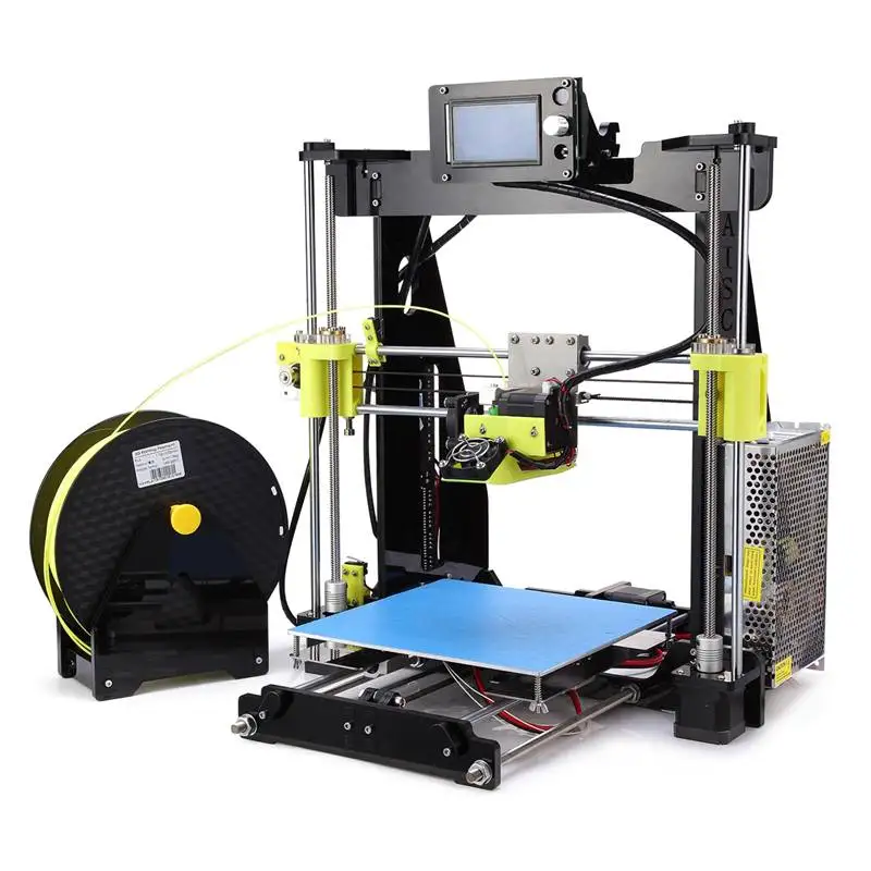
Whether it's just a hobby or a source of income, 3D printing is always based on product design. Those accustomed to traditional technologies will have to rethink the entire approach to product design and manufacture.
When the project is ready, a number of additional operations are performed: setting the orientation of the model and other parameters that ensure the proper printing process. In addition, it is necessary to take into account the fact that most 3D printers allow you to choose the degree of filling the model with cellular structures. The correct choice of this parameter provides protection of the object from deformation and destruction during the printing process, as well as significant savings in material and reduction in production time.
Finally, the last factor influencing the success or failure of the 3D printing process is the strength of the connection between the model and the table. If the workpiece is separated from the table during printing, then all the work will go down the drain.
Here, we'll walk you through the 3D printing process and give you some simple tips on how to use additive manufacturing in the design phase. In addition, we will dwell on the methods of preparing a finished project for printing, and also consider ways to securely fasten the workpiece to the table.
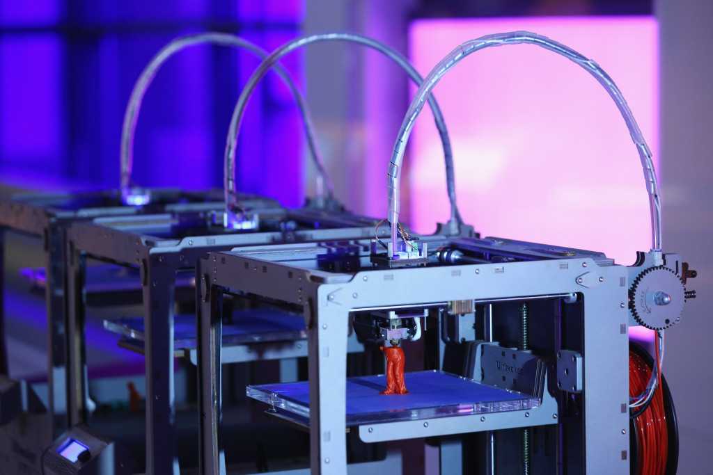
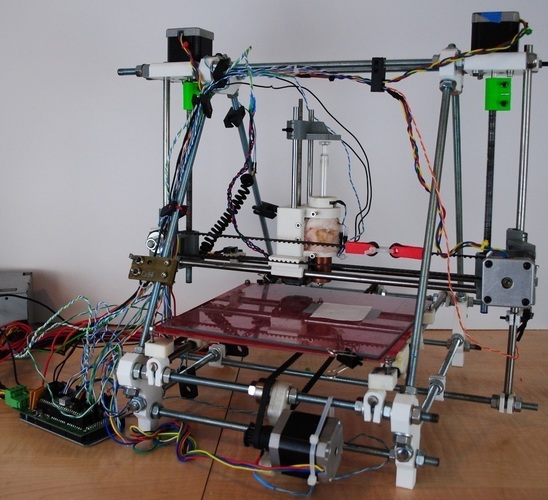
These guidelines apply primarily to Fused Deposition Printers (FDM) printers, but may apply to other types of printers as well. The process of obtaining a finished part by 3D printing is basically the same regardless of the method used.
Designing an object
Any 3D printing starts with construction. If you are developing a product yourself, then you need to build a 3D model of it in a computer-aided design (CAD) system to turn the designer's idea into reality. In this case, the object can be both very simple and very complex. However, too thin and too small models should be avoided.
3D-CAD from Siemens from this article for 49900r (90% discount), the promotion is valid until March 20, 2020. Read more>>
Saving the file in a special format for printing
To print an object, its model must be saved in a special file format - for example, STL, which has become the de facto standard in the world of 3D printing. In this format, model surfaces are represented as a grid of triangles. Simple surfaces are broken down into a small number of triangles. The more complex the surface, the more triangles you will need. Today, other formats are used in 3D printing, in particular, the 3MF format developed by Microsoft. But the most common is still STL.
CAD systems make it very easy to save the model in the desired format: just click the Save As command. To improve print quality, it is desirable to set a number of settings for saving to the STL format - for example, the tolerance during transformation and the angle of the plane. The lower the conversion factor and the better the angle, the smoother the printed part will be.
Opening the file in the slicer program
Most, if not all, 3D printers come with their own slicer software. The slicer loads the STL file created in the CAD system and cuts it into layers, and then creates a control program for the printer.
Place the model correctly in the print space
After entering the print settings, the model (or several models) needs to be placed on the printer table. You can print many objects on one table at once. At the same time, compared to printing a single object, the time slightly increases, but in general it still turns out to be less. Here are some tips for choosing the right model orientation.
Set parameters
In the slicer program, the user sets parameters such as print speed, material consumption, nozzle and desktop temperatures. Most slicers have simple settings for beginners. In this case, most often there are also advanced settings so that experienced professionals can achieve optimal results. Advanced settings include percentage infill, amount of backing material, and type of backing or raft (this is a small, thin base that keeps the printed part stable. The backing is removed when it's finished). The number of options is truly endless. Specific settings vary depending on the brand of printer. It's easy enough to set them up.
Sending the control program to the printer
After setting the print settings, the placement of future objects on the table, their orientation and quality, it's time to finally start the printer. It is enough to press the Print button and find something to do while the production is in progress. Depending on the complexity of the design, the process takes from several minutes to several hours.
Finishing
Finishing includes removing the printed part from the table, as well as removing the support material by melting, mechanical separation or dissolution (depending on the design of the printer). The part may require some light sanding or polishing, but overall a properly printed object looks good from the start. Other types of finishing are placing plastic parts in a container with acetone to smooth out surface roughness, gluing (if the dimensions of the structure exceed the dimensions of the 3D printer or individual elements of the object must have different orientations), drilling holes and painting.
3D printing process
3D printer design considerations
Eliminate sharp corners
If the direction of the surfaces changes abruptly (for example, a vertical wall intersects with a horizontal overlap), then such a model is difficult to print. The printer will build excessive inner surfaces, wasting too much material. There are two easy ways to prevent this: add chamfers to smooth out where the surfaces meet, or round the corners so the printer gradually builds a vertical surface. In addition, rounding will increase strength, since destruction most often occurs at sharp corners.
Elimination of thin walls and small geometries
Layer by layer fusing technology consists in supplying hot plastic through a nozzle with the formation of a printed object layer by layer. The thickness of the extruded plastic layer cannot be made smaller than a certain limit, depending on the diameter of the nozzle and the speed of the print head. Excessively thin-walled details are difficult to print - often the result is a chaotic weave of fibers. If the part can be printed, it is very fragile and breaks easily.
Too thick walls - also bad
On the other hand, if the walls are too thick, they become brittle and crack easily. This is especially important when printing from materials other than resins, as excess thickness during the manufacturing process leads to internal stresses in the part. Even when printing from plastics, material is wasted on walls that are too thick and time is wasted.
Removing large overhangs
3D printers allow you to create amazing shapes and surfaces, but they are not capable of printing directly in the air. If there is a void in the part with material above it, additional support material must be used. Most slicers add material automatically, but require you to specify the orientation and volume of the support structure. Printers with a single nozzle create an array of thin columns, which then have to be broken off. The result is an uneven surface. Therefore, it is recommended to avoid large overhanging elements whenever possible in order to reduce the need for support material.
If such an element is unavoidable, you can try to flip the object. Most printers are capable of printing overhanging elements with an angle of about 45 degrees. At a certain height, the edge of such an element may sag somewhat.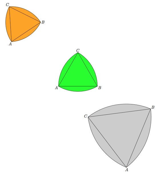 The actual capabilities of a particular printer are determined by trial and error.
Holes shrink
Remember that the part is made of heated plastic. As it cools, it inevitably shrinks. Therefore, holes and other critical structural elements have to be made larger so that after shrinkage their size is as close as possible to the required one.
However, if you need to make a tight tolerance hole, it is better to print it with a smaller diameter and then ream it with a suitable tool. This is especially true for holes whose axis is parallel to the printer table.
Increasing the footprint
If the area of contact between the object and the base is small, the part may separate from the table during printing. To prevent this from happening, wide bases are added to the model legs, which are installed on the printer table. In general, the closer to the table, the more material must be added to the support. There are other ways to securely fasten the part to the table, which we will discuss a little later.
Special moves
The right approach to design makes printing easier. In addition, there are special post-processing techniques that are important to be aware of.
Place round surfaces vertically
The model should be oriented so that the minimum amount of support material is used. Ideally, it should rest on the table with a large flat edge. In addition, circular geometry must be placed so that the circular faces are vertical. If we look at the printer table from above, we should see a round silhouette of the object. In this case, the part comes out as symmetrical as possible with the formation of a solid round structure.
Place voids and holes vertically
If there are voids in the model (for example, it is a rectangular pipe), it is desirable to place such voids vertically in order to reduce the volume of the support material. If you print the pipe in a horizontal position, you will have to provide support for the entire inside. If you put the pipe on the end, then no support is required at all.
The same is true for holes: to get a hole with a straight axis, it is best to print it vertically - in the form of a stack of rings, which avoids warping or deforming a round hole into an oval one.
Set print quality settings
Proper selection of print parameters, such as STL conversion tolerance and slicer software settings, allows parts to be produced with a surface quality that matches that of cutting. However, this entails an increase in print time. When choosing quality parameters, one should proceed from the purpose of the object: is it a finished product or a prototype? Will the part be visible or hidden?
The quality parameters also affect the shape of the holes in the part. In CAD files, holes are represented as a set of straight lines at an angle to each other. The higher the quality of the model in the saved STL file, the less the circle looks like a polygon.
Reducing the layer thickness
To obtain the best quality, especially when using layer-by-layer deposition technology, it is necessary to reduce the thickness of the layers. It does increase the print time, but the end result is worth it!
Optimizing the filling with honeycomb structures
In terms of strength, objects do not have to be solid. Similar to a honeycomb, printers can create a honeycomb infill that balances strength and saves expensive polymer material. However, if the printed part serves as a prototype for strength testing, and the serial product will be manufactured by traditional methods, and also if the part is subjected to certain types of mechanical stresses and pressures, a solid design will be preferable.
Choosing a material
The success of printing largely depends on the correct choice of material. Materials have different properties. For example, the melting point of thermoplastic polyurethane (TPU) and polylactic acid (PLA) is lower than that of acrylonitrile butadiene styrene (ABS). In addition, the material is taken into account when choosing the type of support structures. For an object made of polylactic acid, supporting elements can be made from the same polylactic acid, since it will be quite easy to separate them from the finished part. If the part is printed from ABS plastic, then the support elements must be made from a different material, and it is better not to use such elements at all in thermoplastic polyurethane parts.
Cellular filling
A solid body is not always the best choice for 3D printing. Printing solid parts has its advantages, but the internal honeycomb structure saves both expensive material and time.
Creating objects with a specified degree of filling with honeycomb structures is a unique opportunity for 3D printing.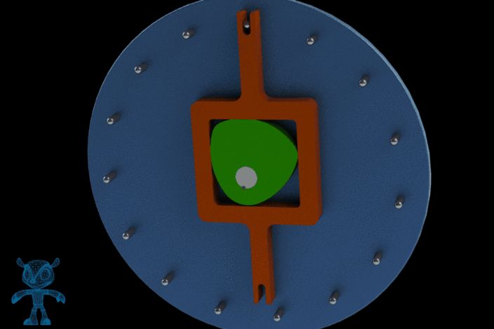 Moreover, it is not required to design such a structure: this is done by the slicer program. As a rule, it is enough to set only the percentage of filling (the closer it is to 100, the more solid the object will turn out) and select the type of cells, if the printer has such an opportunity.
In addition to saving time and material, the internal honeycomb structure has many other advantages.
Cellular filling prevents warpage
Printing large objects as a single piece introduces a danger of warpage. By reducing the infill percentage, the air during printing passes through the part, providing more uniform cooling and eliminating warpage.
Cellular filling does not lead to loss of strength
Printing cells instead of solid material does not reduce the strength of the part. In many cases, a honeycomb part is strong enough for the chosen application, but lighter and less material intensive.
The function determines the choice of cell geometry
Most slicers support a wide variety of cell geometries. The optimal option is determined by the functional purpose of the object. Standard box padding simplifies printing, while hexagonal and triangular boxes add strength. Wave fill allows the object to bend or twist.
How to choose the right filling percentage?
In general, the strength of an object increases as the percentage of infill increases. Most printers have a default infill percentage of 20, which is optimal in some cases but too high or too low in others. Consider mechanical stresses in the printed object and increase the percentage of infill in areas where greater strength is required. If high strength is not required, choose the lowest possible filling. This saves material and speeds up printing. Most often, the selection of the optimal percentage of filling is done by trial and error.
Ways of fastening the workpiece to the table
“Rafts”, “brims”, “skirts” – these terms sound funny, but they just refer to the three main ways of attaching a 3D printed part to a printer table. Let's take a look at each of these methods and their areas of application.
Skirt
The skirt involves creating a few rings around the object at the beginning of the print to make sure the plastic is extruded normally. The skirt is not in contact with the object at all. It surrounds the printable area and helps start the fusing process. When creating a skirt, a large volume of hot thermoplastic polymer passes through the nozzle. This prepares the printer for printing the part itself. This guarantees good adhesion to the table and obtaining smooth surfaces of the object.
Brim
The brim is a wide, flat area connected to the main object as a support base (think of a brim of a hat).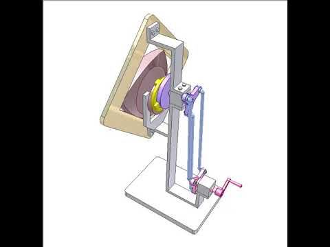 It is very similar to a skirt, but connected to the model. In addition to all the advantages of a skirt, the brim keeps the edges of the object being made on the table.
When printing, the outside of an object often cools faster than the middle, causing the edges to curl. Brim prevents this phenomenon by holding the edges.
Raft
A raft is a detachable base, made in the form of a thin mesh platform, located under the entire object (which lies on the raft). To create a raft, the printer first prints a flat plate in two or three layers, and then begins to manufacture the object.
The rafts provide excellent adhesion to the table surface and also provide a strong print base. This is especially useful when making small and oddly shaped parts that do not fit well on the table, as well as thin-walled objects.
After printing is completed, in most cases the raft will separate easily from the part.
If the printer does not have a heated desktop function
Rafts are used if the printer does not have desktop heating. In this case, excessive adhesion becomes a problem.
An alternative method is to apply adhesive paper tape to the printer bed, with the edges down if possible (this also protects the bed). You can also use packing tape, but it is usually more expensive.
If buckling does occur or the object separates from the table, apply a dissolvable glue stick to the adhesive tape. This will enhance adhesion.
Find out the features of a specific 3D printer and take them into account when preparing a model
3D printing is not only a science, but also an art. Effective design for subsequent 3D printing requires an understanding of the technological process, taking into account its features and the purpose of the future object. This will greatly improve print performance.
Using Solid Edge in 3D printing
Not all CAD systems are suitable for 3D printing
The capabilities of the applied system should not limit the designers. Our Solid Edge system is designed with the latest 3D printing technologies in mind. Various 3D printers and 3D printing services are supported.
Take it to the next level with specific techniques for designing 3D printed parts
Generative modeling in Solid Edge opens up new possibilities: the designer selects a specific material, sets the design space, allowable loads, restrictions and target mass of the part, and the system automatically calculates the desired geometry. As a result, 3D printing methods can produce the most complex shapes.
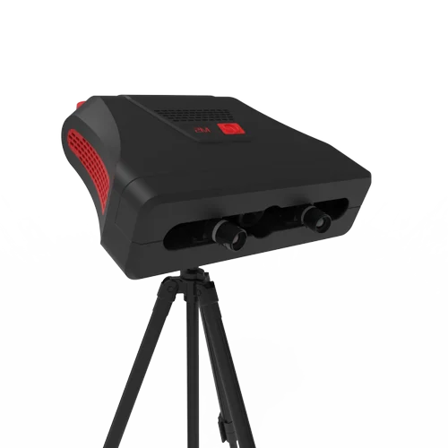
In addition, when building models, the use of the results of three-dimensional scanning is provided. Solid Edge successfully combines the traditional boundary representation of solid models (B-Rep) and the representation of surfaces in the form of a grid of triangles, which avoids time-consuming transformations that are fraught with errors.
If you've already downloaded an STL file for printing, our unique synchronous technology makes it quick and easy to edit your imported models in Solid Edge in preparation for the process.
Printing with your own printer or submitting an order to a 3D printing service provider
Printing in Solid Edge on a local 3D printer is done using the 3D print command. Models can be saved in STL and 3MF formats, or sent directly to Microsoft 3D Builder. If you don't have your own 3D printer or need to try out different materials and surface finishes, Solid Edge allows you to directly submit your models to cloud-based 3D printing services (such as 3YOURMIND). You immediately receive quotes for the production of parts from various materials with its subsequent delivery directly to your door.
3D-CAD from Siemens from this article for 49900r (90% discount), the promotion is valid until March 20, 2020. More>>
Round Reuleaux Triangle / Etudes // Mathematical Etudes
Round Reuleaux Triangle / Etudes // Mathematical EtudesMathematical Etudes
Back to List
Luch-2 8mm film projector. It was he who was in every house where they themselves filmed and watched film sketches.
This cartoon tells how a geometric concept, often studied in math circles, finds application in our daily life.
Wheel… Circumference. One of the properties of a circle is its constant width. Draw two parallel tangents and fix the distance between them. Let's start spinning. The curve (in our case, the circle) constantly touches both lines. This is the definition of a closed curve having a constant width.
Are there curves other than circles that have a constant width?
RELO Franz 1829-1905
Reuleaux Franz is a German scientist. For the first time (1875) he clearly formulated and outlined the main issues of the structure and kinematics of mechanisms; developed the problem of aesthetics of technical objects.
Consider a regular triangle (with equal sides). On each side we construct an arc of a circle, with a radius equal to the length of the side. This curve is called the Reuleaux triangle. It turns out that it is also a curve of constant width.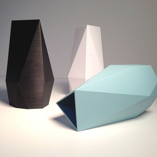 As in the case of a circle, we draw two tangents, fix the distance between them and start rotating them. The Reuleaux triangle constantly touches both lines. Indeed, one point of contact is always located in one of the "corners" of the Reuleaux triangle, and the other - on the opposite arc of the circle. So the width is always equal to the radius of the circles, i.e., the length of the side of the original regular triangle.
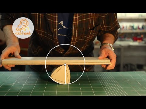
In everyday terms, the constant width of the curve means that if you make rollers with such a profile, then the book will roll along them without moving.
However, a wheel with such a profile cannot be made, since its center describes a complex line when the figure rolls in a straight line.
Are there any other constant width curves? It turns out there are an infinite number of them.
On any regular n-gon with an odd number of vertices, it is possible to construct a curve of constant width in the same way as the Reuleaux triangle was constructed. From each vertex, as from the center, we draw an arc of a circle on the opposite side of the vertex. In England, the 20 pence coin is shaped like a curve of constant width built on a heptagon.
The considered curves do not exhaust the entire class of curves of constant width. It turns out that among them there are asymmetric curves. Consider an arbitrary set of intersecting lines. Let's consider one of the sectors. Let's draw an arc of a circle of arbitrary radius with the center at the point of intersection of the lines, defining this sector. Let's take a neighboring sector, and with the center at the point of intersection of the lines that define it, draw a circle. Radius is selected such that the already drawn piece of the curve continues continuously. We will continue to do so. It turns out that with such a construction, the curve closes and will have a constant width. Prove it!
All curves of a given constant width have the same perimeter. The circle and the Reuleaux triangle are distinguished from the entire set of curves of a given width by their extreme properties. The circle limits the maximum area, and the Reuleaux triangle - the minimum in the class of curves of a given width.
The Reuleaux triangle is often studied in math circles. It turns out that this geometric figure has interesting applications in mechanics.
Look, this is a Mazda RX-7. Unlike most production cars, it (as well as the RX-8 model) has a Wankel rotary engine. How is it arranged inside? It is the Reuleaux triangle that is used as the rotor! Three chambers are formed between it and the walls, each of which in turn is the combustion chamber. Here, a blue gasoline mixture was splashed, then, due to the movement of the rotor, it is compressed, ignited and turns the rotor. A rotary engine is devoid of some of the disadvantages of a piston analogue - here the rotation is transferred directly to the axis and there is no need to use a crankshaft.
And this is the clamshell mechanism. It was used in movie projectors. The motors give uniform rotation of the axis, and in order to have a clear image on the screen, the film must be pulled past the lens for one frame, let it stand, then sharply pulled again, and so on 18 times per second. It is this problem that is solved grab mechanism. It is based on a Reuleaux triangle inscribed in a square and a double parallelogram that keeps the square from tilting to the sides. Indeed, since the lengths of the opposite sides are equal, the middle link remains parallel to the base during all movements, and the side of the square is always parallel to the middle link. The closer the attachment axis is to the top of the Reuleaux triangle, the closer to the square, the figure is described by the tooth of the clamshell.
These are interesting applications of a seemingly purely mathematical problem that people use.
Literature
Boltyansky V. G., Yaglom I. M. Convex figures. - M.-L.: GTTI, 1951.
G. Rademacher, O. Teplitz. Numbers and Figures: Experiments of Mathematical Thinking. - M.: ONTI, 1936. - (Library of the Mathematical Circle; Issue 10). — [Reprints: 1938, 1962, 1966, 2020].
See also
Figures of constant width // Mathematical component / Ed.