Rectilinear 3d printing
Infill patterns | Prusa Knowledge Base
Relevant for
:
MINIMINI+MK2.5MK2.5SMK2SMK3MK3SMK3S+MMU1MMU2SPlus 1.75 mm
Last updated
3 months ago
This article is also available in following languages:
PrusaSlicer offers many infill patterns to choose from. When choosing an infill pattern, these are the main things to consider:
- Print speed
- Density per material used (better support for top layers with less material)
- Visuals
- Support for top layers
- Flexibility (for TPU/TPE prints)
Different infill patterns are used for some, but usually not all applications:
- low-density filling of the inside of a model
- filling the top layers
- filling the bottom layers
- generating support material
Infill types and their properties
Gyroid infill
The Gyroid is our favorite and one of the best infills. It’s one of the few 3D structures that provide great support in every direction. Plus it’s printed relatively fast, saves material, doesn’t cross itself at one layer and looks great. The special shape of this infill allows filling it with resin or another liquid.
- It's 3 dimensional - giving it equal strength in all directions
- It can be printed fairly quickly
- It doesn't cross itself in the same layer
- It has a good strength/weight ratio
- It allows filling it with resin or another liquid.
- (We think) it looks really neat
Cubic
This is an infill with paths that cross each other within one layer. It creates cubes oriented with one corner facing down. This way it makes numerous air pockets that might serve as heat insulation, or cause the object to float on water (with waterproof filaments such as PETG). Print time and filament consumption does not differ from the previous infills.
Adaptive cubic infill
The Adaptive cubic infill works on the same principle as cubic. It consists of cubes oriented corner-down where lines cross themselves in one layer. Unlike simple cubic infill, this infill gets automatically more or lense dense, depending on the distance to the nearest wall, leaving large cavities in the middle. This is especially useful for large prints with a big internal volume. The print will have denser infill at the top, bottom and around all sides, but it will have lower density near the center of the volume. The result is shorter print time and lower filament consumption while maintaining great support for top layers and similar mechanical properties. Material consumption is approx. 1/4 less than the rectilinear infill.
The Adaptive Cubic infill works by refining those cells of an octree, that contain any object triangle. Anchors are added to each infill line. This makes the infill sturdier and it stabilizes the extrusion flow at the start of an infill line.
Support cubic infill
This infill gets automatically denser depending on the distance to the nearest top layer (the infill density increases only in the Z-axis). ts primary function is to support top layers by saving as much material as possible, it doesn’t improve any mechanical qualities of the model. Material consumption and print time of this infill are by far the lowest of all the supported infills.
Rectilinear
Rectilinear is one of the basic infill patterns. It creates a rectilinear grid by printing one layer in one direction, the next layer rotated by 90°, etc. This way, it saves filament and doesn’t accumulate material at crossings (unlike grid). It’s one of the fastest printed infills.
Compared to the Grid pattern, Rectilinear has double the support for top layers using the same amount of material.
This type of infill is the only one recommended for 100% infill printing. If you have another type of infill set in your profile and change the infill percentage to 100% density, PrusaSlicer will automatically change the infill type to rectilinear.
Aligned rectilinear
This infill is formed by parallel lines drawn inside the model, which resemble the outside support structures. Similar to the previous type, this infill saves time, has average material consumption, plus it doesn’t accumulate material at crossings. However, using this infill might cause some trouble when the direction of the lines in the infill is the same as in the infill of the first top solid layer – if they are perfectly parallel, the top layers might have issues with bridging.
Grid
This is one of the simplest and fastest variants of infill. Unlike rectilinear, it’s printed in both directions (rotated by 90°) in each layer. This way, material accumulates in spots where the paths cross. The grid infill is more solid (and has better layer adhesion) than the rectilinear infill, however, it sometimes can cause annoying noise or even a print failure due to the nozzle going over the crossings where material accumulates.
Due to the way this infill is printed, the paths cross and cause the material to accumulate in these spots. You may hear a specific noise as the nozzle hits these parts. This may even lead to a failed print.
Triangles
This infill works similarly to the grid infill – the paths cross in one layer, however, this time they are printed in three directions and form a triangle structure. Material and time consumption is almost identical to the grid.
Stars
The Stars infill is based on triangles but paths are shifted to make six-pointed stars. Again, this infill is created by lines that cross each other within a single layer. Material and time consumption is similar to the previous infill.
Line
The Line is one of the infills that don’t feature any crossing paths in one layer. Its paths are similar to the rectilinear infill but they are not parallel to each other. Instead, they are printed at an acute angle. Unsurprisingly, this infill is similar to rectilinear when it comes to printing time and material consumption.
Concentric
The concentric infill traces the model perimeter lines and makes them smaller towards the center. In other words: if you print a cylinder, the concentric infill will create concentric circles inside that cylinder. This can be useful with transparent parts or flexible models (RC tires for example). The main disadvantage is the time spent printing. Material consumption is not higher than previous types of infill patterns.
Honeycomb
This infill prints a grid made of hexagons. Its main advantage is mechanical resistance and optimal paths without crossings. The main disadvantages are higher material consumption (approx. 25% more) compared to other infills, and print time that can take up to twice the time of previously described options.
3D honeycomb
3D honeycomb prints bigger and smaller squares and octagons to create columns of periodically increasing and decreasing thickness. Again, this infill doesn’t have crossing lines in one layer, however, due to the way it lays down the paths, it creates small gaps between layers. Material consumption and print time are slightly worse compared to the regular honeycomb pattern.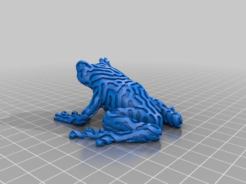
Hilbert curve
The Hilbert curve creates a rectangular labyrinth inside the model. The main advantage of this infill is its non-traditional look, plus it can be pretty easily filled with epoxy resin or another liquid – the model is split into several large cavities, instead of a number of small “bubbles”. The main disadvantage of this infill is increased print time, which sits somewhere between honeycomb and rectilinear infills. The material consumption of the Hilbert curve is similar to the rectilinear.
Archimedean chords
Again, this spiral-twisted infill allows easier filling with liquid. This simple shape saves material and time (compared to the rectilinear infill). Similar to the concentric infill, the Archimedean chords help with model flexibility if you print it with flexible filament.
Octagram spiral
Octagram spiral allows filling the object with liquid easily due to larger compartments made with this type of infill. An Octagram spiral might also help with flexibility for certain models.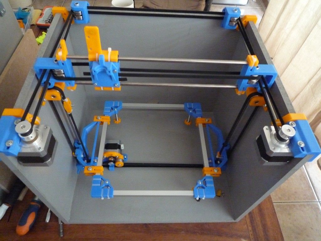 But mostly it’s for aesthetic purposes and top layer support. Material consumption is similar to Archimedean chords but print time is slightly longer.
Lightning
The lighting infill generates a branching structure that gets progressively denser towards the top surfaces to support them reliably. It saves even more material compared to the Support cubic infill. The lighting infill is based on paper and ported from Cura, our thanks go to the Cura team for keeping it open-source.
Types of top (bottom) layer infill
Editing infill doesn’t end with choosing an infill type for the internal parts of the object. You can also change top and bottom layer infill types to get some interesting results. These can be adjusted in the Print settings - Infill -Top (Bottom) fill pattern tab.
All seven types of top (bottom) infills printed with 80% flow to highlight the patterns.
Rectilinear
Again, this is one of the most common (and basic) types of top infill.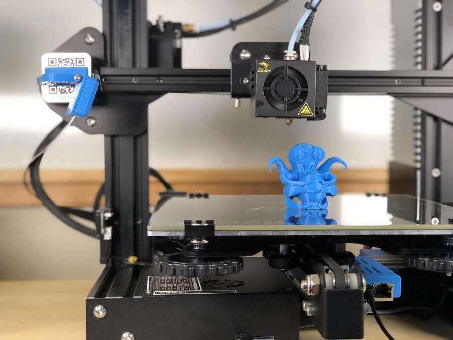 The print paths are oriented zig-zag for the whole layer. However, this is the simplest type of infill that doesn’t provide any advantage whatsoever (see Monotonic infill).
Monotonic infill
The "monotonic" infill is essentially a rectilinear infill with modified path planning. The infill lines are extruded left to right monotonically, a line is never extruded to the left of an already extruded infill line. This strikingly simple strategy leads to a homogenous texture without ugly ridges. Ridges are often created when the left-to-right extrusions meet with right-to-left extrusions in the center of an infill area, while printing left to right only leads to a homogenous shine.
The seemingly simple left-to-right strategy is surprisingly difficult to implement optimally. We have implemented a variant of the Ant Colony System as described by Raad Salman.
Aligned rectilinear
This infill pattern works similarly to the rectilinear infill but the last layers on all top surfaces are aligned in the same direction.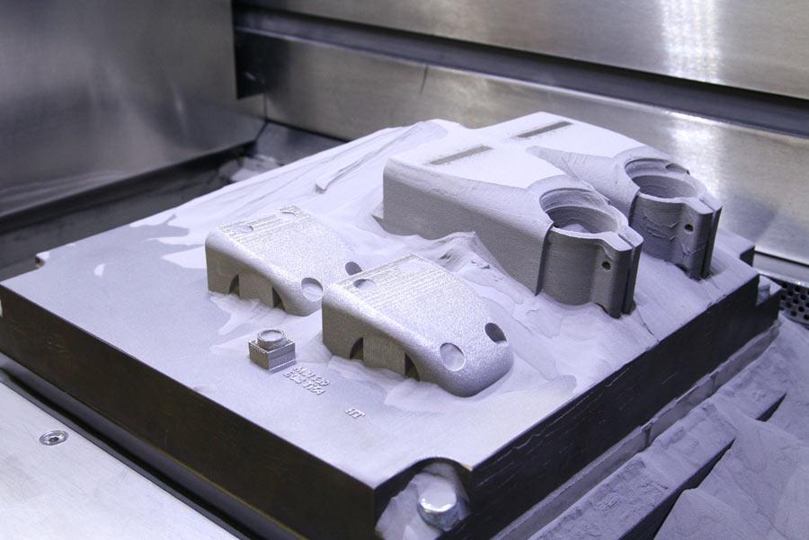 This can help for creating a homogenous top layer pattern for models that have top layers in different heights (imagine a staircase model).
Concentric
The concentric infill pattern copies perimeter shapes. If you print a cylinder, it will create concentric circles on top of the model.
Hilbert curve
This is mostly an aesthetic infill. If it’s printed inside, Hilbert Curve creates rectangular shapes, while the topmost layer looks more like a wicker basket. Some people say that it looks “wormy”. This infill significantly increases the print time due to the complex shape.
Archimedean chords
The topmost layer of archimedean chords is printed in a spiral. This infill can save time when printing certain models.
Octagram spiral
Again, this infill is described above. It’s good mainly for aesthetic purposes but due to the complex shape, it prolongs the print time.
Everything you need to know about infills
You may have noticed that there are new infill patterns in our new version of PrusaSlicer (2.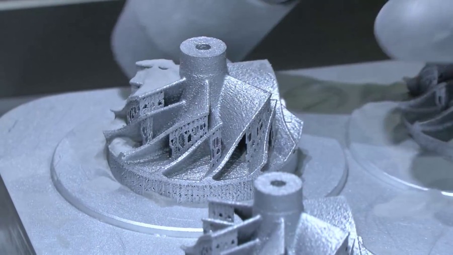 3). Now, with the sheer amount of options, you might even feel overwhelmed with all the possibilities. Which infill should you choose? Is there a single universal pattern that works for every model? Or should you pick depending on a specific case? Let’s take a look at what can be accomplished by using the right kind of infill and adjusting its parameters.
Infill: inner structure of your 3D prints
First, let’s do a quick recap of what an infill is and why it is important. If you are a 3D-printing pro, you may want to skip this chapter, but it never hurts to brush up on the basics, right?
3D printed models are rarely printed solid (100% infill) or completely hollow. Instead, we use a method that fills the inside of an object with a sparse supporting structure. Infill provides internal support for top layers, which would otherwise have to bridge over empty space. This helps keep the model solid and prevents gaps and holes from appearing on the object’s top surfaces.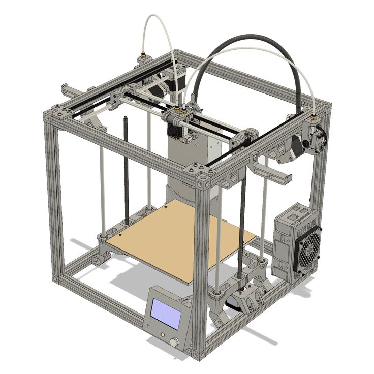 Solid models (100% infill) consume large amounts of filament and time. Also, in most cases, solid models won’t provide better mechanical properties compared to models with a sparser infill. If you decide to print a model without an infill, you’re risking that the surface of angled walls and top layers will be compromised – there might be small gaps or even large holes. It’s pretty much obvious that the best solution lies somewhere in between. With proper infill settings, you can save a lot of material and time but also create some interesting patterns on the surface.
Most of the time, it makes very little sense to set the infill density higher than 40 %. Our testing revealed that the best density setting is 10-20%, and we implemented this value in our PrusaSlicer profiles. 10-20% is the ideal balance between strength, print reliability, print time, and material consumption. Of course, for some objects, a 5% (or lower) infill might be enough, especially large simple parts printed with PLA.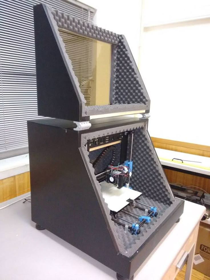 With density higher than 20% comes higher tenacity. However, the same effect can be achieved by adding more perimeters as well (Print settings/Layers and perimeters). With different print settings, you can change not only the internal structure and mechanical properties but also print speed, material consumption and the object’s surface.
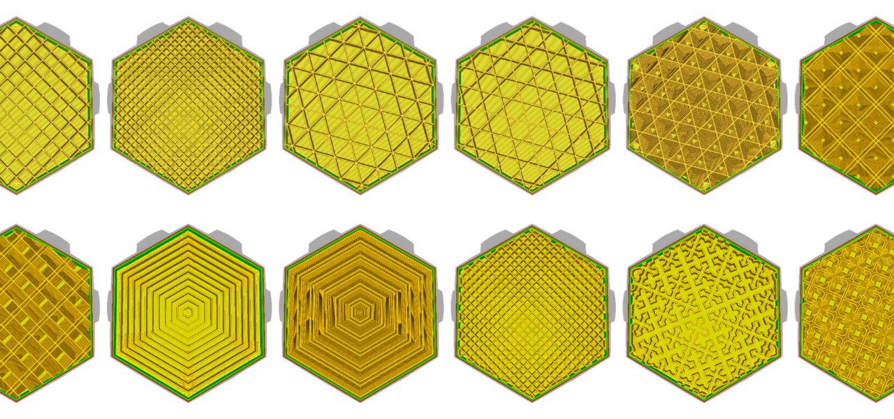
Before we start with advanced settings, let’s take a quick look at all available types of infills and their properties one by one.
Infill types and their properties
The list of infills has grown a lot and it might be difficult to choose the right type. Although you may feel they differ mostly in appearance, the opposite is true. For example, some infills may save us a lot of material and time, some can be filled with liquid, etc.
Rectilinear
Rectilinear is one of the basic infill patterns. It creates a rectilinear grid by printing one layer in one direction, the next layer rotated by 90°, etc.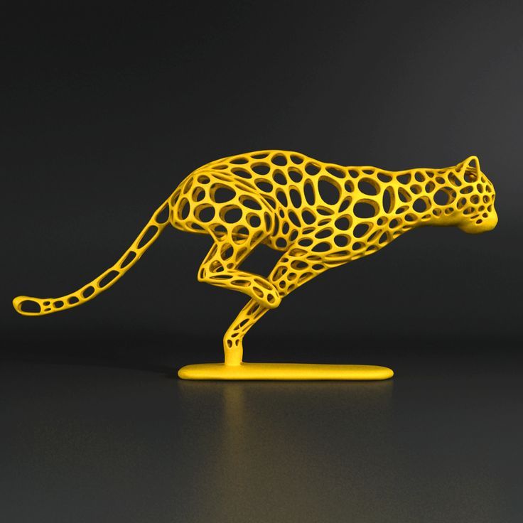 This way, it saves filament and doesn’t accumulate material at crossings (unlike grid). It’s one of the fastest printed infills.
This type of infill is the only one recommended for 100% infill printing. If you have another type of infill set in your profile and change the infill percentage to 100% density, PrusaSlicer will automatically change the infill type to rectilinear.
Aligned rectilinear
This infill is formed by parallel lines drawn inside the model, which resemble the outside support structures. Similar to the previous type, this infill saves time, has average material consumption, plus it doesn’t accumulate material at crossings. However, using this infill might cause some trouble when the direction of the lines in the infill is the same as in the infill of the first top solid layer – if they are perfectly parallel, the top layers might have issues with bridging.
Grid
This is one of the simplest and fastest variants of infill. Unlike rectilinear, it’s printed in both directions (rotated by 90°) in each layer. This way, material accumulates in spots where the paths cross. The grid infill is more solid (and has better layer adhesion) than the rectilinear infill, however, it sometimes can cause annoying noise or even a print failure due to the nozzle going over the crossings where material accumulates.
Due to the way this infill is printed, the paths cross and cause the material to accumulate in these spots. You may hear a specific noise as the nozzle hits these parts. This may even lead to a failed print.
Triangles
This infill works similarly to the grid infill – the paths cross in one layer, however, this time they are printed in three directions and form a triangle structure. Material and time consumption is almost identical to the grid.
Stars
The Stars infill is based on triangles but paths are shifted to make six-pointed stars. Again, this infill is created by lines that cross each other within a single layer. Material and time consumption is similar to the previous infill.
Cubic
Again, this is an infill with paths that cross each other within one layer. However, unlike previously described infills, it creates cubes oriented with one corner facing down. This way it makes numerous air pockets that might serve as heat insulation, or cause the object to float on water (with waterproof filaments such as PETG). Print time and filament consumption does not differ from the previous infills.
Line
The Line is one of the infills that don’t feature any crossing paths in one layer. Its paths are similar to the rectilinear infill but they are not parallel to each other. Instead, they are printed at an acute angle. Unsurprisingly, this infill is similar to rectilinear when it comes to printing time and material consumption.
Concentric
The concentric infill traces the model perimeter lines and makes them smaller towards the center. In other words: if you print a cylinder, the concentric infill will create concentric circles inside that cylinder. This can be useful with transparent parts or flexible models (RC tires for example). The main disadvantage is the time spent printing. Material consumption is not higher than previous types of infill patterns.
Honeycomb
This infill prints a grid made of hexagons. Its main advantage is mechanical resistance and optimal paths without crossings. The main disadvantages are higher material consumption (approx. 25% more) compared to other infills, and print time that can take up to twice the time of previously described options.
3D honeycomb
3D honeycomb prints bigger and smaller squares and octagons to create columns of periodically increasing and decreasing thickness. Again, this infill doesn’t have crossing lines in one layer, however, due to the way it lays down the paths, it creates small gaps between layers. Material consumption and print time are slightly worse compared to the regular honeycomb pattern.
Gyroid
The Gyroid is our favorite and one of the best infills. It’s one of the few 3D structures that provide great support in every direction. Plus it’s printed relatively fast, saves material, doesn’t have crossing lines in one layer and looks great. The special shape of this infill allows filling it with epoxy resin or another liquid.
Hilbert curve
The Hilbert curve creates a rectangular labyrinth inside the model. The main advantage of this infill is its non-traditional look, plus it can be pretty easily filled with epoxy resin or another liquid – the model is split into several large cavities, instead of a number of small “bubbles”. The main disadvantage of this infill is increased print time, which sits somewhere between honeycomb and rectilinear infills. The material consumption of the Hilbert curve is similar to the rectilinear.
Archimedean chords
Again, this spiral-twisted infill allows easier filling with liquid. This simple shape saves material and time (compared to the rectilinear infill). Similar to the concentric infill, the Archimedean chords help with model flexibility if you print it with flexible filament.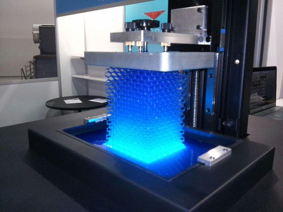
Octagram spiral
Octagram spiral allows filling the object with liquid easily due to larger compartments made with this type of infill. An Octagram spiral might also help with flexibility for certain models. But mostly it’s for aesthetic purposes and top layer support. Material consumption is similar to Archimedean chords but print time is slightly longer.
Adaptive cubic
The adaptive cubic infill works on the same principle as cubic: It consists of cubes oriented corner-down where lines cross themselves in one layer. But there’s one great advantage: Unlike a simple cubic infill, this pattern makes the infill denser towards the model edges, leaving large cavities in the middle. Material consumption is approx. ¼ less than the rectilinear infill.
The Adaptive Cubic infill works by refining those cells of an octree, that contain any object triangle. Anchors are added to each infill line. This makes the infill sturdier and it stabilizes the extrusion flow at the start of an infill line. Basically, This infill gets automatically more or less dense, depending on the distance to the nearest wall. This is especially useful for large prints with a big internal volume. The result is shorter print time and lower filament consumption while maintaining great support for top layers and similar mechanical properties.
Support cubic
The support cubic infill works similarly to the previous type but with one difference: the infill density increases only in the Z-axis. Its primary function is to support top layers by saving as much material as possible, it doesn’t improve any mechanical qualities of the model. Material consumption and print time of this infill are by far the lowest of all the supported infills.
Types of top (bottom) layer infill
Editing infill doesn’t end with choosing an infill type for the internal parts of the object.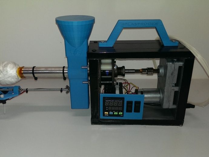 You can also change top and bottom layer infill types to get some interesting results. These can be adjusted in the Print settings/Infill/Top (Bottom) fill pattern tab. However, changing the top or bottom infill mostly affects the aesthetic changes and does not improve the mechanical properties of the model.
All seven types of the top (bottom) infills printed with 80% flow to highlight the patterns.
Rectilinear
Again, this is one of the most common (and basic) types of top infill. The print paths are oriented zig-zag for the whole layer. However, this is the simplest type of infill that doesn’t provide any advantage whatsoever (see Monotonic infill).
Monotonic
The monotonic infill pattern fills the top (bottom) layer with parallel lines, similar to the rectilinear infill type. However, this infill works with advanced path planning. Unlike rectilinear, this infill is always printed left to right and never in the opposite direction.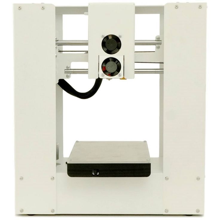 This simple system leads to achieving a homogenous infill without ugly ridges. These usually appear with other infills when left to right paths meet the right to left ones. This seemingly simple method is surprisingly hard to implement. We used the Ant Colony System variant described by Raad Salman.
Aligned rectilinear
This infill pattern works similarly to the rectilinear infill but the last layers on all top surfaces are aligned in the same direction. This can help for creating a homogenous top layer pattern for models that have top layers in different heights (imagine a staircase model).
Concentric
The concentric infill pattern copies perimeter shapes. If you print a cylinder, it will create concentric circles on top of the model.
Hilbert curve
This is mostly an aesthetic infill. If it’s printed inside, Hilbert Curve creates rectangular shapes, while the topmost layer looks more like a wicker basket.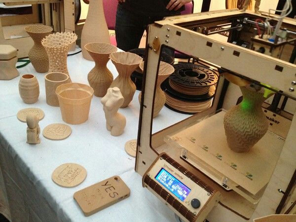 Some people say that it looks “wormy”. This infill significantly increases the print time due to the complex shape.
Archimedean chords
The topmost layer of archimedean chords is printed in a spiral. This infill can save time when printing certain models.
Octagram spiral
Again, this infill is described above. It’s good mainly for aesthetic purposes but due to the complex shape, it prolongs the print time.
Advanced settings
PrusaSlicer lets you adjust infill patterns even more! If you switch to the Advanced or Expert mode, you’ll find a lot more settings in the Infill tab. Let’s take a look at all the settings related to infills, regardless of whether it’s in Advanced or Expert mode:
Length of the infill anchor
The infill is usually connected to the perimeters with a so-called anchor, which is a short line of another (inner) perimeter that turns into an infill line. The length of the infill anchor value sets how many millimeters of this anchor will connect the infill and the perimeters. If you set this value to 0, the infill will be printed independently on the perimeters. Set a higher value to print the anchor that will continue as the infill itself. The infill anchor helps to increase model integrity and toughness.
The maximum length of the infill anchor
This value sets the maximum length of the infill anchor connecting the infill with perimeters.
Ironing
Ironing creates a smooth top surface on horizontal planes – filament paths are almost invisible. How is this achieved? The hot nozzle goes over the surface one more time but with low filament flow. Turning the ironing on or off, and/or choosing the ironing type (all top surfaces, topmost surface only, all solid surfaces) should be enough for most 3D printer users. However, some may want to tweak the flow rate or spacing between ironing passes. The flow rate is set as a percentage linked to the normal layer height, the spacing between ironing passes tells how far the parallel nozzle tracks should be from each other. These parameter values are set to optimal values, but you can experiment with them as you wish if you are not happy with the results.
If you increase flow, you risk that material leftovers will remain on the surface. Also, the nozzle tracks may remain visible. Lower flow, on the other hand, will leave the last layer paths visible due to a lack of material filling the gaps.
Spacing between ironing passes has a great influence on the top layer visibility too. To make it a bit easier to imagine, we’ll compare it to a snowplow. Let’s say you use only a part of the plow blade to clean off the snow – it will remove some amount of snow and clean the plowed part of the road, too. However, if you dig the entire plow blade into the snow and move forward, you’ll create a path, but there will be excess snow left behind.
To find out more about ironing, read our older article.
Reducing printing time
PrusaSlicer offers two variants of saving time and material. The first option is combining infill every X layers. The default value is set to 1, where every perimeter layer is printed with one infill layer (1 = ratio of 1 infill layer per 1 perimeter layer). Increasing the value to 2 (2:1 ratio) will print one layer of infill (of according layer height) for every two perimeter layers. But keep in mind that this value cannot be increased infinitely. PrusaSlicer will let you set it very high but the only maximal physically possible value will be written into G-code. To be specific: If you use a 0.4mm nozzle and 0.15mm layer height, the slicer won’t let you print one infill layer less often than every two perimeter layers. Otherwise, the infill would be printed to empty space. But if you print with 0.05mm layer height (0.4mm nozzle), you can combine infill every 6 layers (maximum layer height is 0. 3mm).
3mm).
The second variant of saving time (and material) is printing infill only where needed. For example, if you print a sphere, this function will make only an infill column in the center to support possible overhangs. The main disadvantage of this function is low denting resistance due to the lack of infill in some model parts.
Advanced
These infill settings are truly advanced stuff and most 3D printer users won’t even come close to ever needing them. However, there might be some special cases when you’ll need to adjust them, so let’s take a look at what they do:
Printing solid infill every X layers can come in handy when you want to increase the model’s toughness (increasing the number of perimeters works better, though) or dividing it into multiple cavities that might be useful if you want the object to float on water. This function simply causes a solid infill to be printed at regular intervals.
Fill angle rotates its pattern by chosen angle.
Solid infill threshold area is useful mostly for tiny and complex parts. With this setting, you can adjust how large or small cavities of the model should be filled with a 100% infill. This can help to make thin parts stronger.
A bridging angle is calculated by PrusaSlicer automatically. If you leave it at 0°, PrusaSlicer will choose the best value. However, you can change it manually if you wish. Printing with a bridging angle equal to 0° can be achieved by setting it to 180°.
Only retracting when crossing perimeters can reduce printing time a little and increase infill integrity. Turning retractions off will increase filament dripping that won’t be visible (hidden inside model). Retractions will remain turned on for perimeters.
Printing Infill before perimeters might sometimes help with printing overhangs where perimeters have nothing to attach to. However, infill might negatively impact the quality of the external surface. The second usage of this method is for MMU2s where wiping colors gets better results – the color is cleaned to infill and the perimeter is printed with clean color.
And this concludes our deep dive into the world of infill patterns. We offer our own in-house tested PrusaSlicer profiles with tweaked values, which should work for a vast majority of users. However, if you feel like your prints are not 100% up to par, or you would like to experiment a little bit, don’t be afraid to adjust the values. A good way to compare your results is to print a set of sample models and inspect how the adjusted values affect the result. If you want to step up your 3D printing game, experimenting with infills is a recommended option – your models may become nicer, more durable, or you can even discover brand new uses for them because some of the infills e.g. improve the floating capabilities of printed models. So go ahead, have fun, and as always: Happy printing!
short tips for the transition from a CAD model to a printed object / Sudo Null IT News
was withdrawn from publication due to a technical error.Please be understanding. Thank you!
Whether it's just a hobby or a source of income, 3D printing is always based on product design. Those accustomed to traditional technologies will have to rethink the entire approach to product design and manufacture.
When the project is ready, a number of additional operations are performed: setting the orientation of the model and other parameters that ensure the proper printing process. In addition, it is necessary to take into account the fact that most 3D printers allow you to choose the degree of filling the model with cellular structures. The correct choice of this parameter provides protection of the object from deformation and destruction during the printing process, as well as significant savings in material and reduction in production time.
Finally, the last factor influencing the success or failure of the 3D printing process is the strength of the connection between the model and the table. If the workpiece is separated from the table during printing, then all the work will go down the drain.
Here, we'll walk you through the 3D printing process and give you some simple tips on how to use additive manufacturing in the design phase. In addition, we will dwell on the methods of preparing a finished project for printing, and also consider ways to securely fasten the workpiece to the table.
These guidelines apply primarily to Fused Deposition Printers (FDM) printers, but may apply to other types of printers as well. The process of obtaining a finished part by 3D printing is basically the same regardless of the method used.
Designing an object
Any 3D printing starts with construction. If you are developing a product yourself, then you need to build a 3D model of it in a computer-aided design (CAD) system to turn the designer's idea into reality. In this case, the object can be both very simple and very complex. However, too thin and too small models should be avoided.
3D-CAD from Siemens from this article for 49900r (90% discount), the promotion is valid until March 20, 2020. Read more>>
Saving the file in a special format for printing
To print an object, its model must be saved in a special file format - for example, STL, which has become the de facto standard in the world of 3D printing. In this format, model surfaces are represented as a grid of triangles. Simple surfaces are broken down into a small number of triangles. The more complex the surface, the more triangles you will need. Today, other formats are used in 3D printing, in particular, the 3MF format developed by Microsoft. But the most common is still STL.
CAD systems make it very easy to save the model in the desired format: just click the Save As command. To improve print quality, it is desirable to set a number of settings for saving to the STL format - for example, the tolerance during transformation and the angle of the plane. The lower the conversion factor and the better the angle, the smoother the printed part will be.
Opening the file in the slicer program
Most, if not all, 3D printers come with their own slicer software. The slicer loads the STL file created in the CAD system and cuts it into layers, and then creates a control program for the printer.
Place the model correctly in the print space
After entering the print settings, the model (or several models) needs to be placed on the printer table. You can print many objects on one table at once. At the same time, compared to printing a single object, the time slightly increases, but in general it still turns out to be less. Here are some tips for choosing the right model orientation.
Set parameters
In the slicer program, the user sets parameters such as print speed, material consumption, nozzle and desktop temperatures.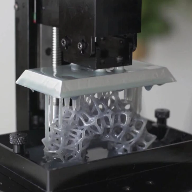 Most slicers have simple settings for beginners. In this case, most often there are also advanced settings so that experienced professionals can achieve optimal results. Advanced settings include percentage infill, amount of backing material, and type of backing or raft (this is a small, thin base that keeps the printed part stable. The backing is removed when it's finished). The number of options is truly endless. Specific settings vary depending on the brand of printer. It's easy enough to set them up.
Sending the control program to the printer
After setting the print settings, the placement of future objects on the table, their orientation and quality, it's time to finally start the printer. It is enough to press the Print button and find something to do while the production is in progress. Depending on the complexity of the design, the process takes from several minutes to several hours.
Finishing
Finishing includes removing the printed part from the table, as well as removing the support material by melting, mechanical separation or dissolution (depending on the design of the printer). The part may require some light sanding or polishing, but overall a properly printed object looks good from the start. Other types of finishing are placing plastic parts in a container with acetone to smooth out surface roughness, gluing (if the dimensions of the structure exceed the dimensions of the 3D printer or individual elements of the object must have different orientations), drilling holes and painting.
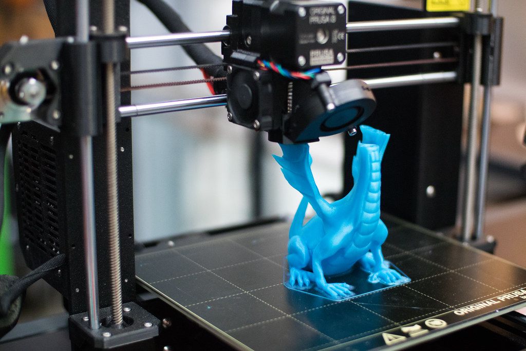
3D printing process
3D printer design considerations
Eliminate sharp corners
If the direction of the surfaces changes abruptly (for example, a vertical wall intersects with a horizontal overlap), then such a model is difficult to print. The printer will build excessive inner surfaces, wasting too much material. There are two easy ways to prevent this: add chamfers to smooth out where the surfaces meet, or round the corners so the printer gradually builds a vertical surface.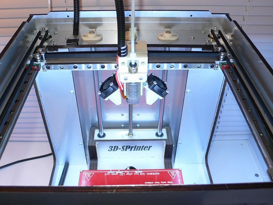 In addition, rounding will increase strength, since destruction most often occurs at sharp corners.
Elimination of thin walls and small geometries
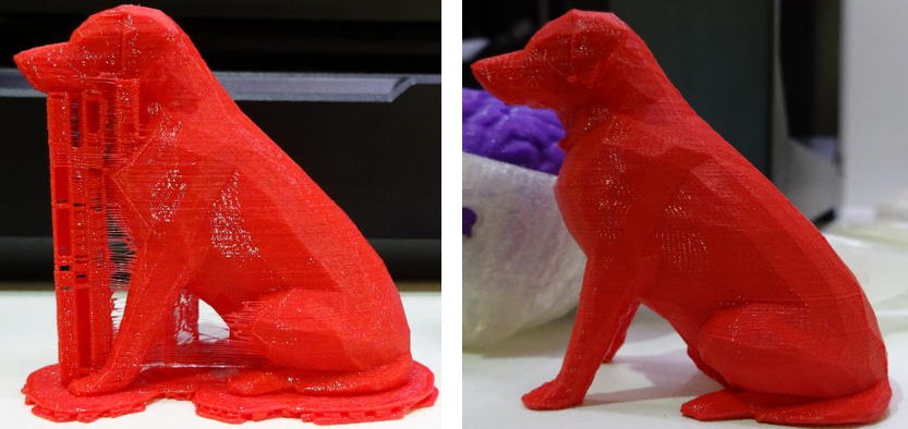
Layer by layer fusing technology consists in supplying hot plastic through a nozzle with the formation of a printed object layer by layer. The thickness of the extruded plastic layer cannot be made smaller than a certain limit, depending on the diameter of the nozzle and the speed of the print head. Excessively thin-walled details are difficult to print - often the result is a chaotic weave of fibers. If the part can be printed, it is very fragile and breaks easily.
Too thick walls - also bad
On the other hand, if the walls are too thick, they become brittle and crack easily. This is especially important when printing from materials other than resins, as excess thickness during the manufacturing process leads to internal stresses in the part.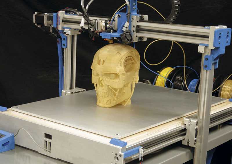 Even when printing from plastics, material is wasted on walls that are too thick and time is wasted.
Removing large overhangs
3D printers allow you to create amazing shapes and surfaces, but they are not capable of printing directly in the air. If there is a void in the part with material above it, additional support material must be used. Most slicers add material automatically, but require you to specify the orientation and volume of the support structure. Printers with a single nozzle create an array of thin columns, which then have to be broken off. The result is an uneven surface. Therefore, it is recommended to avoid large overhanging elements whenever possible in order to reduce the need for support material.
If such an element is unavoidable, you can try to flip the object. Most printers are capable of printing overhanging elements with an angle of about 45 degrees. At a certain height, the edge of such an element may sag somewhat.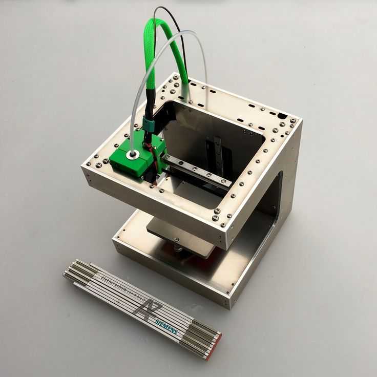 The actual capabilities of a particular printer are determined by trial and error.
Holes shrink
Remember that the part is made of heated plastic. As it cools, it inevitably shrinks. Therefore, holes and other critical structural elements have to be made larger so that after shrinkage their size is as close as possible to the required one.
However, if you need to make a tight tolerance hole, it is better to print it with a smaller diameter and then ream it with a suitable tool. This is especially true for holes whose axis is parallel to the printer table.
Increasing the footprint
If the area of contact between the object and the base is small, the part may separate from the table during printing. To prevent this from happening, wide bases are added to the model legs, which are installed on the printer table. In general, the closer to the table, the more material must be added to the support.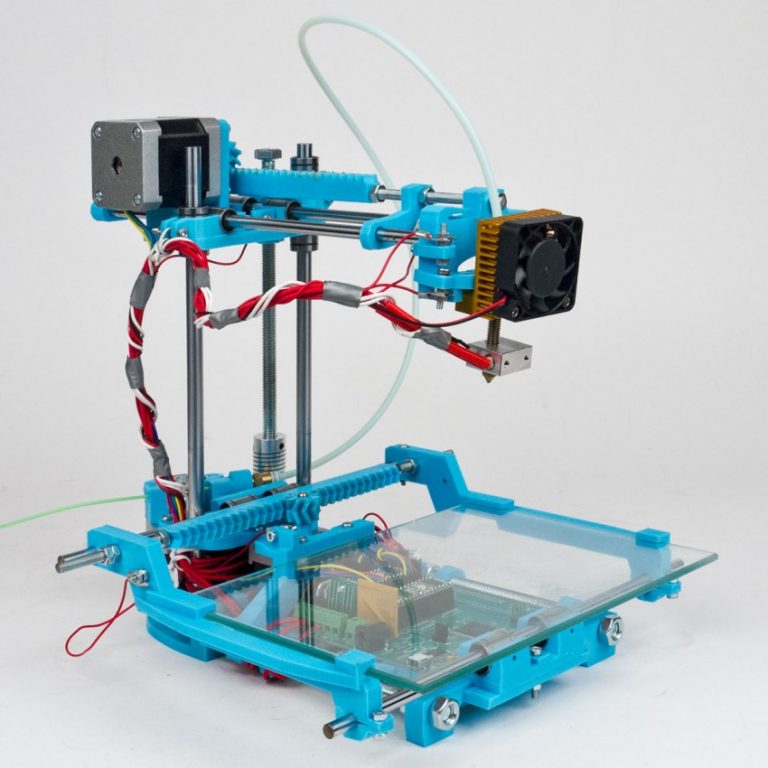 There are other ways to securely fasten the part to the table, which we will discuss a little later.
Special moves
The right approach to design makes printing easier. In addition, there are special post-processing techniques that are important to be aware of.
Place round surfaces vertically
The model should be oriented so that the minimum amount of support material is used. Ideally, it should rest on the table with a large flat edge. In addition, circular geometry must be placed so that the circular faces are vertical. If we look at the printer table from above, we should see a round silhouette of the object. In this case, the part comes out as symmetrical as possible with the formation of a solid round structure.
Place voids and holes vertically
If there are voids in the model (for example, it is a rectangular pipe), it is desirable to place such voids vertically in order to reduce the volume of the support material.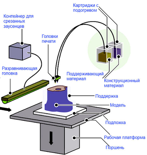 If you print the pipe in a horizontal position, you will have to provide support for the entire interior. If you put the pipe on the end, then no support is required at all.
The same is true for holes: to get a hole with a straight axis, it is best to print it vertically - in the form of a stack of rings, which avoids warping or deforming a round hole into an oval one.
Set print quality settings
Proper selection of print parameters, such as STL conversion tolerance and slicer software settings, allows parts to be produced with a surface quality that matches that of cutting. However, this entails an increase in print time. When choosing quality parameters, one should proceed from the purpose of the object: is it a finished product or a prototype? Will the part be visible or hidden?
The quality parameters also affect the shape of the holes in the part. In CAD files, holes are represented as a set of straight lines at an angle to each other. The higher the quality of the model in the saved STL file, the less the circle looks like a polygon.
Reducing the layer thickness
To obtain the best quality, especially when using layer-by-layer deposition technology, it is necessary to reduce the thickness of the layers. It does increase the print time, but the end result is worth it!
Optimizing the filling with honeycomb structures
In terms of strength, objects do not have to be solid. Similar to a honeycomb, printers can create a honeycomb infill that balances strength and saves expensive polymer material. However, if the printed part serves as a prototype for strength testing, and the serial product will be manufactured by traditional methods, and also if the part is subjected to certain types of mechanical stresses and pressures, a solid design will be preferable.
Choosing a material
The success of printing largely depends on the correct choice of material. Materials have different properties. For example, the melting point of thermoplastic polyurethane (TPU) and polylactic acid (PLA) is lower than that of acrylonitrile butadiene styrene (ABS). In addition, the material is taken into account when choosing the type of support structures. For an object made of polylactic acid, supporting elements can be made from the same polylactic acid, since it will be quite easy to separate them from the finished part. If the part is printed from ABS plastic, then the support elements must be made from a different material, and it is better not to use such elements at all in thermoplastic polyurethane parts.
Cellular filling
A solid body is not always the best choice for 3D printing. Printing solid parts has its advantages, but the internal honeycomb structure saves both expensive material and time.
Creating objects with a specified degree of filling with honeycomb structures is a unique opportunity for 3D printing. Moreover, it is not required to design such a structure: this is done by the slicer program. As a rule, it is enough to set only the percentage of filling (the closer it is to 100, the more solid the object will turn out) and select the type of cells, if the printer has such an opportunity.
In addition to saving time and material, the internal honeycomb structure has many other advantages.
Cellular filling prevents warpage
Printing large objects as a single piece introduces a danger of warpage. By reducing the infill percentage, the air during printing passes through the part, providing more uniform cooling and eliminating warpage.
Cellular filling does not lead to loss of strength
Printing cells instead of solid material does not reduce the strength of the part. In many cases, a honeycomb part is strong enough for the chosen application, but lighter and less material intensive.
The function determines the choice of cell geometry
Most slicers support a wide variety of cell geometries. The optimal option is determined by the functional purpose of the object. Standard box padding simplifies printing, while hexagonal and triangular boxes add strength. Wave fill allows the object to bend or twist.
How to choose the right filling percentage?
In general, the strength of an object increases as the percentage of infill increases. Most printers have a default infill percentage of 20, which is optimal in some cases but too high or too low in others. Consider mechanical stresses in the printed object and increase the percentage of infill in areas where greater strength is required. If high strength is not required, choose the lowest possible filling. This saves material and speeds up printing. Most often, the selection of the optimal percentage of filling is done by trial and error.
Ways of fastening the workpiece to the table
“Rafts”, “brims”, “skirts” – these terms sound funny, but they just refer to the three main ways of attaching a 3D printed part to a printer table. Let's take a look at each of these methods and their areas of application.
Skirt
The skirt involves creating a few rings around the object at the beginning of the print to make sure the plastic is extruded normally. The skirt is not in contact with the object at all. It surrounds the printable area and helps start the fusing process. When creating a skirt, a large volume of hot thermoplastic polymer passes through the nozzle. This prepares the printer for printing the part itself. This guarantees good adhesion to the table and obtaining smooth surfaces of the object.
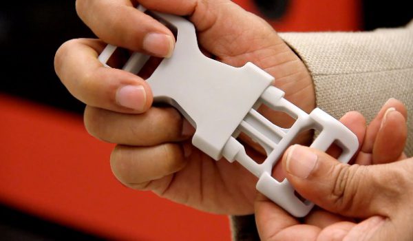
Brim
The brim is a wide, flat area connected to the main object as a support base (think of a brim of a hat). It is very similar to a skirt, but connected to the model. In addition to all the advantages of a skirt, the brim keeps the edges of the object being made on the table.
When printing, the outside of an object often cools faster than the middle, causing the edges to curl. Brim prevents this phenomenon by holding the edges.
Raft
A raft is a detachable base, made in the form of a thin mesh platform, located under the entire object (which lies on the raft). To create a raft, the printer first prints a flat plate in two or three layers, and then begins to manufacture the object.
The rafts provide excellent adhesion to the table surface and also provide a strong print base. This is especially useful when making small and oddly shaped parts that do not fit well on the table, as well as thin-walled objects.
After printing is completed, in most cases the raft will separate easily from the part.
If the printer does not have a heated desktop function
Rafts are used if the printer does not have desktop heating. In this case, excessive adhesion becomes a problem.
An alternative method is to apply adhesive paper tape to the printer bed, with the edges down if possible (this also protects the bed). You can also use packing tape, but it is usually more expensive.
If buckling does occur or the object separates from the table, apply a dissolvable glue stick to the adhesive tape. This will enhance adhesion.
Find out the features of a specific 3D printer and take them into account when preparing a model
3D printing is not only a science, but also an art. Effective design for subsequent 3D printing requires an understanding of the technological process, taking into account its features and the purpose of the future object. This will greatly improve print performance.
Using Solid Edge in 3D printing
Not all CAD systems are suitable for 3D printing
The capabilities of the applied system should not limit the designers. Our Solid Edge system is designed with the latest 3D printing technologies in mind. Various 3D printers and 3D printing services are supported.
Take it to the next level with specific techniques for designing 3D printed parts
Generative modeling in Solid Edge opens up new possibilities: the designer selects a specific material, sets the design space, allowable loads, restrictions and target mass of the part, and the system automatically calculates the desired geometry. As a result, 3D printing methods can produce the most complex shapes.
In addition, when building models, the use of the results of three-dimensional scanning is provided. Solid Edge successfully combines the traditional boundary representation of solid models (B-Rep) and the representation of surfaces in the form of a grid of triangles, which avoids time-consuming transformations that are fraught with errors.
If you've already downloaded an STL file for printing, our unique synchronous technology makes it quick and easy to edit your imported models in Solid Edge in preparation for the process.
Printing with your own printer or submitting an order to a 3D printing service provider
Printing in Solid Edge on a local 3D printer is done using the 3D print command. Models can be saved in STL and 3MF formats, or sent directly to Microsoft 3D Builder. If you don't have your own 3D printer or need to try out different materials and surface finishes, Solid Edge allows you to directly submit your models to cloud-based 3D printing services (such as 3YOURMIND). You immediately receive quotes for the production of parts from various materials with its subsequent delivery directly to your door.
3D-CAD from Siemens from this article for 49900r (90% discount), the promotion is valid until March 20, 2020. Read more>>
What do the specifications of a 3D printer mean? » Profitable 3D printing studio
As I wrote the other day, I am currently writing a book on choosing a 3D printer. The working title is “How to choose a 3D printer” In it, I will tell you what to pay attention to first of all for a beginner.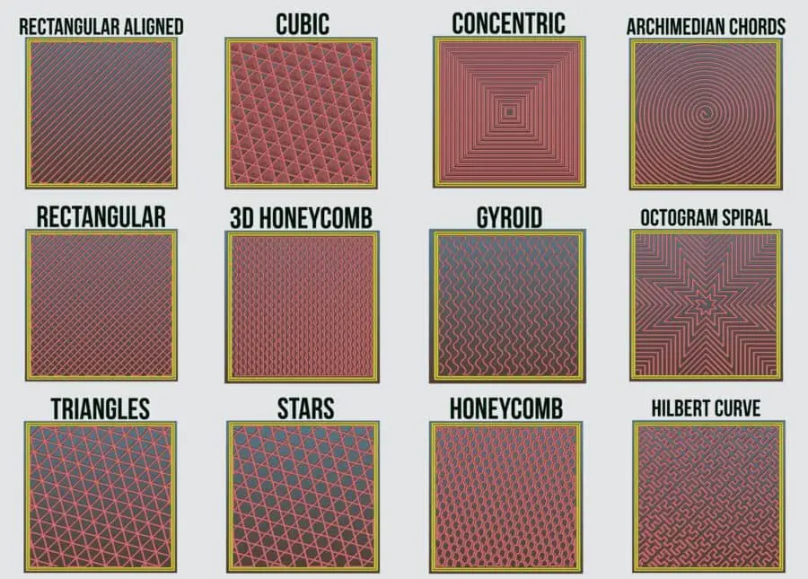 And what does this or that parameter mean. What are the schemes of 3D printers. And a lot of what is scattered over various discussions. Here the information will be compiled in one place. The book will be FREE, with free distribution.
Below is a draft of one chapter, in which I will look at what the individual characteristics of 3D printers, which are published by equipment manufacturers and sellers, mean.
Using the Zenit 3D printer as an example, let's take a look at the specs and I'll explain what they mean.
· Printable area: 240 x 215 x 230 mm
One of the main parameters. Tells us what is the maximum size we can print a part. In fact, the printable area is usually slightly smaller. And in reality, details of this size are not printed. Typically, a part can be larger than one of the sizes. But here we must understand that we can place the part diagonally on the desktop. Therefore, the maximum length of a part is usually limited by the length of the table diagonal.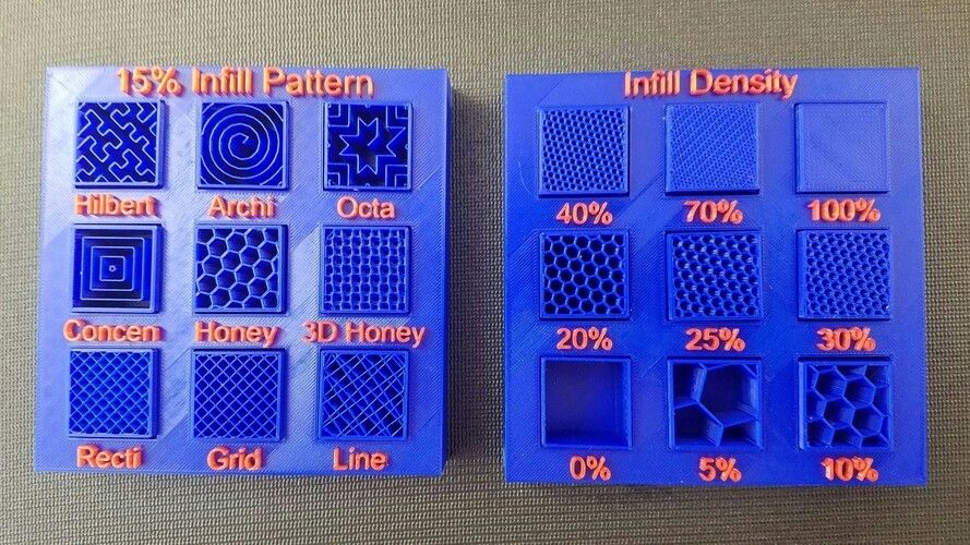 Although in some cases it is possible to connect a third dimension. But here we must already take into account the direction of the layers.
· X, Y axis positioning accuracy: 0.04mm
An important parameter that affects print quality. This is how accurately the printer can position the extruder over the printable area. Achieved with good mechanics. Tensioned belts. And greased guides.
· Z-axis positioning accuracy: 0.01mm
Also an important parameter that affects the quality. It depends entirely on the implementation of movement along the Z axis. There are different implementation options. We will consider them later.
Filament diameter: 1.75 mm
Parameter that tells us about the consumables used by the 3D printer. Now, in fact, there are two sizes of filament: 1.75 mm and 2.85 (3.00) mm.
1.75mm is now the most common. Such plastic is used by most 3D printers. All new materials first appear in this diameter.
2. 85mm or 3.00mm older size. It is now used in 3D printers, Ultimaker clones and various homemade products. The original Ultimaker uses a diameter of 2.85mm. 3.00mm plastic is usually produced by "non-mainstream" manufacturers. And it is used in clones and DIYs.
There is no significant difference in usage between these standards. The only thing is that for 1.75mm there are more types of media offered for printing. Basic ABS, PLA plastics for both standard sizes are in stock.
There are also technical differences in the extruder scheme used. The so-called Bowden extruder is more adapted to the "thick" plastic 2.85 (3.00) mm. This is one of the reasons why 2.5mm filament is used in Ultimaker 3D printers equipped with similar extruders.
Nozzle diameter, mm: 0.3
Everything is simple here. The thinner the nozzle, the more accurately we can print the part. In theory. In fact, a thinner nozzle is prone to clogging. And starting with a diameter of 0.2 mm, this can be a serious problem.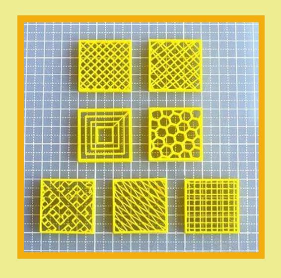
The second reason is that as the nozzle diameter decreases, the print time increases. Here the dependence is linear - the smaller the diameter of the nozzle - it is necessary to go through more layers and passages in order for the walls to have sufficient strength.
As a result, the most common nozzles are 0.3-0.4 mm in diameter. They achieve decent accuracy. And the print time is quite adequate.
Larger diameter nozzles 0.5-1.0mm are commonly used in printers with a large printable area. With them, a speed is achieved that is more important when printing large parts than the quality of printing small parts of a model.
In most printers, the nozzles can be changed and the correct diameter can be used for your job. But in fact, by setting 0.3-0.4mm you will close 95% of all possible tasks.
· Layer height : 50 to 150 microns
Many manufacturers declare layer heights as low as 50 microns. This is 0.05mm. For most, the lower limit is 50-100 microns. Here you need to understand - the thinner the layer, the more the printing time increases. That is, a part with a layer of 0.05 mm will be printed at least twice as long as a part with a layer of 0.1 mm.
Therefore, for most applications, a lower limit of 0.1 mm or 100 microns is more than sufficient.
As for the upper limit of the thickness, there is also a dependence here. For high-quality printing, it is necessary that the layer thickness be no more than 0.5-0.6 of the nozzle diameter. That is, for a nozzle diameter of 0.3 mm, the optimal upper limit of the thickness, as indicated here, is 150 microns or 0.15 mm.
· Print speed: 40-150 mm/s
Print speed is a relative term and is usually achieved on large straight parts. The print speed is uneven and depends on many parameters. And the more complex the model, the slower the print speed. The average speed of most printers lies in the region of 50-100mm/sec. If a printer can't print simple parts well at 50mm/sec with standard PLA or ABS, there's something wrong with it.
As I said, super quality is usually achieved at 30-40mm/sec. This speed is selected either manually in the settings or the slicer itself (print preparation program) itself reduces the speed to adequate values.
· Maximum print head speed: 300mm/s
Parameter that affects print speed. It is indirectly related to the overall print speed.
Demonstrates the maximum speed at which the extruder can move "idle". In theory.
· Heated table: Yes
Another important option that caused a lot of copies to be broken. The presence of a heated table allows you to use almost all available materials for printing. First of all, with a large shrinkage. For example, one of the two most common materials is ABS. But here is a nuance ... Now there are quite a lot of materials that replace ABS in many tasks. If you do not plan to use such plastic, then you can get by with a table without heating. Conclusion - a table with heating is certainly better than without heating. But if you do not plan to use ABS in your tasks, then you can safely do without it.
· Number of printheads: 1
Most 3D printers have one extruder and this is also usually sufficient for the vast majority of applications. The second extruder makes it possible to use the dissolved material to create supports. For example, HIPS or PVA.
You can also print in two colors. But it almost didn't work out. And apart from demonstrating the possibilities, it is usually not seriously used.
In general, two-material printing received its development momentum after the appearance on the market of the PRO250 printer from PICASO. It uses an extruder with JetSwitch rotary nozzles. It allows you to achieve high-quality printing with two materials. And most importantly, he dramatically reduced the printing time with two materials. The fact is that when printing with two materials, when the extruders are located next to each other, you have to build an additional technological “tower” next to the part. This leads to a significant increase in print time. Switching between extruders can take several minutes.
Therefore, if you do not need to print complex models, then most likely you will not need a second extruder.
· Software : RepetierHost, Slic3r, Cura
With the exception of some 3D printers with their own software, most can work with universal programs. Both paid and free. These are Cura, RepetierHost, Slic3r, Simplify3D and many others.
· Computer connection: USB
Most 3D printers connect to a computer via USB. Although more and more new models are appearing that also support connecting to the network using WiFi or Ethenet.
· SD card printing: Yes
This is the more important setting. Almost all printers have it. But there are still printers that cannot print from Flash or SD cards.
Why is this necessary? If possible, start printing using such memory cards. Printing via USB can lead to marriage.