Next 3d scanner
NextEngine 3D Laser Scanner
Hardware
Software
Accessories
Service
3D Scanner Ultra HD
Learn More
To capture all the stuff you work with, you want 3D input at your fingertips. NextEngine's exclusive Multi-Laser Technology delivers superior precision and fidelity. Find out what has made NextEngine's Desktop 3D Scanner the World's best-seller. New Ultra HD sensors deliver stunning resolution.
$2,995
Buy Now
30-Day Money-Back Guarantee
MultiDrive
Learn More
Fully automate alignment of multiple scans with tilt/rotary object positioning. Define multiple scan families and with one click execute creation of your 3D mesh model. Just trim unwanted overlapping scan
data, fuse, and polish. A new level of simplicity for NextEngine 3D
Scanner users.
$995
Buy Now
30-Day Money-Back Guarantee
ScanStudio
Learn More
Every NextEngine 3D Scanner comes equipped with high performance Scanning and Modeling Software at no extra charge. ScanStudio manages your scanner hardware, refines your data, and assembles it into a fully healed precise mesh model.
STANDARD
ScanStudio ProScan
Learn More
Increase your scanner performance with the ScanStudio ProScan upgrade. Double scan speed for faster cycle times and capture more surface area with Large Format mode.>
$995
Buy Now
30-Day Money-Back Guarantee
CAD TOOLS
Learn More
Want to convert your mesh model into a CAD model? Need spline outputs or NURBS surfaces? Want to quickly determine volume or surface area? ScanStudio CAD TOOLS gets the job done in one integrated and quick to learn package.
$995
Buy Now
30-Day Money-Back Guarantee
RapidWorks 4.0
Learn More
Are you a Solid Modeling CAD expert? If you need industrial-strength tools to convert Scans to CAD parts, RapidWorks is the World's state-of-the-art in Engineering Software for 3D scan data.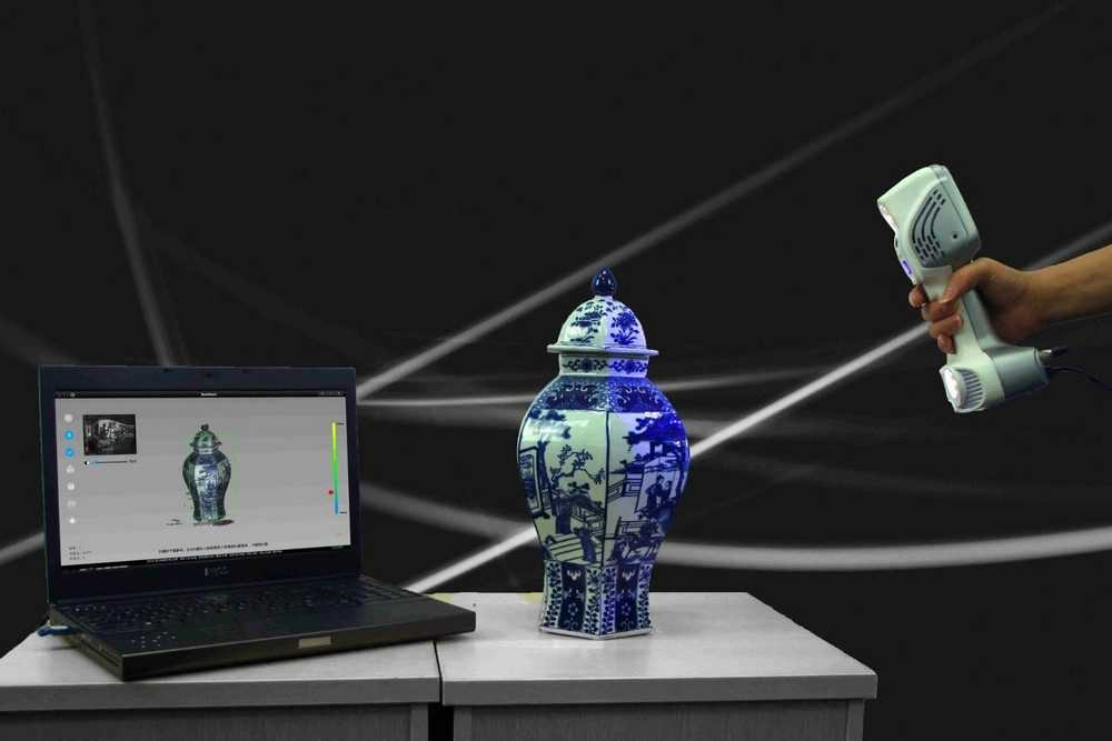 Get robust full feature set design tools for under 3K!
$2,995
Buy Now
30-Day Money-Back Guarantee
QA-Scan 4.0
Learn More
Need fast verification that a physical sample meets design requirements?
QA-Scan provides easy-to-use tools for precisely comparing 3D scans with CAD models. Made for high volume applications, QA-Scan automatically aligns your data, checks tolerances, and produces detailed GD&T reports.
$1,995
Buy Now
3D Curriculum
Learn More
Ten simple lesson plans help students become proficient with the NextEngine 3D Scanner and RapidWorks reverse engineering software. Capture the imagination of your students as they explore the future of 3D design.
$995
Buy Now
Black Bases
Reduce trimming time, replace white platforms on your AutoDrive or MultiDrive positioner with black platforms nearly invisible to the scanner.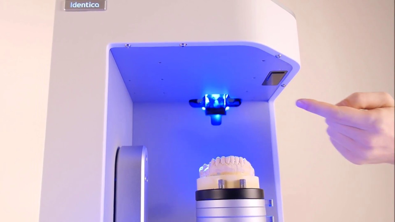
$10
Buy Now
AutoDrive Extension
24 inch extension between Scanner and AutoDrive increases flexibility to orientate large objects.
$10
Buy Now
PaintPens
Learn More
Scan your transparent or mirror-finish objects with these convenient valve-action paint pens. Coat parts with water-based white tempra paint for excellent scanability. Wipes off with a damp sponge. Use at your desk and store in a drawer. One set of PaintPens is included with your scanner.
$15
Buy Now
Extra PowderPen
Learn More
Scan shiny objects with handy pushbutton powder brush pen. Coat parts with microfine talc granules suspended with a trace of lanolin for mild clinging to surfaces. Wipes off easily with a tissue. One PowderPen is included with your scanner.
$10
Buy Now
Extra PartGripper
Learn More
Adjustable stainless steel part-holding fixture has soft silicone pads to protect and grip your part.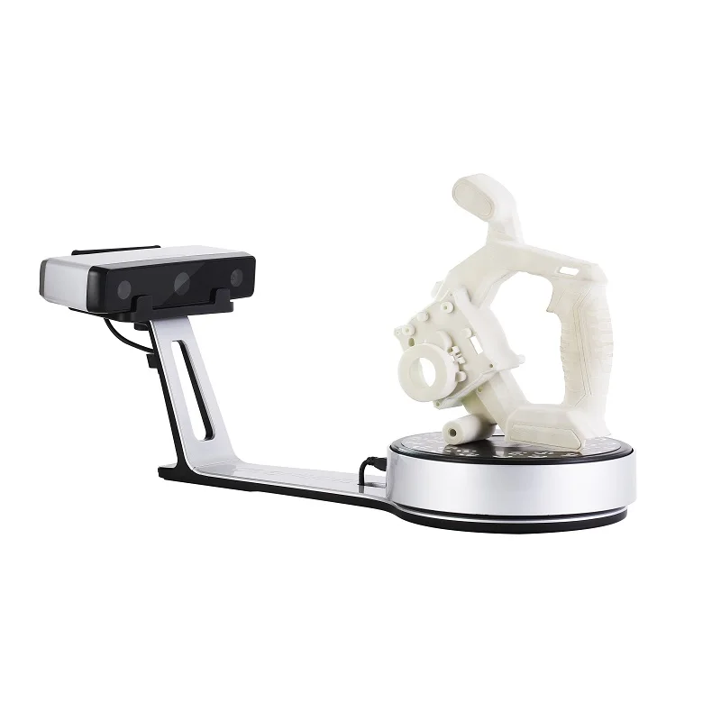 Use additional Grippers for difficult objects, or to modify for special purpose jigs. One PartGripper is included with your scanner.
$55
Buy Now
3 Year Extended Warranty
Total warranty coverage for your 3D scanner for repair/replacement of any defect for 3 full years. No charge for any parts, labor, or services.
$295
Buy Now
RapidWorks ProCare
Learn More
Talk with our engineers via phone or real-time NextWiki chat, and get one-on-one assistance from reverse engineering experts. 3 Years of Software upgrades for RapidWorks, plus phone support, priority real-time chat, priority e-mail support, and project-specific assistance.
$995
Buy Now
QA-Scan ProCare
Talk with our engineers via phone or real-time NextWiki chat, and get one-on-one assistance from experts. 3 Years of Software upgrades for QA-Scan, plus phone support, priority real-time chat, priority e-mail support, and project-specific assistance.
$795
Buy Now
ScanStudio ProCare
Learn More
Extends support for your Scanner and ScanStudio software for 3 full years. Includes unlimited support and all major software upgrades.
$295
Buy Now
Next Engine - Creating at Cline Library
Next Engine
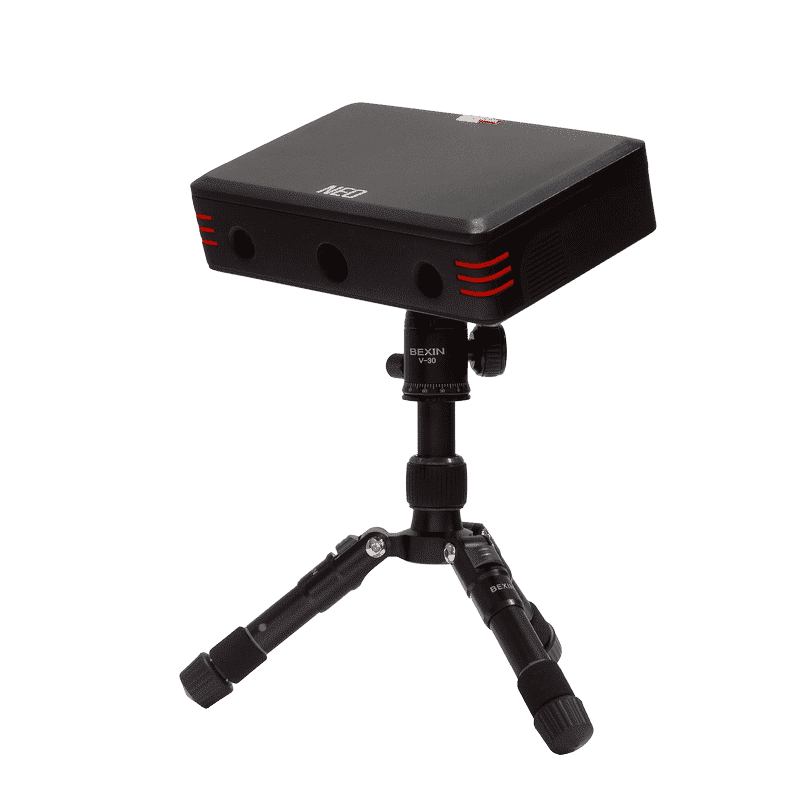
The NextEngine 3D Scanner is a professional desktop scanner with rotating stand that is ideal for scanning smaller detailed items like models, antiques, or artifacts. This scanner uses the ScanStudio software to capture the color and texture of an object up to 0.012 mm resolution. The NextEngine 3D scanner is available for in-library use on a first-come, first-served basis.
- NAU/CCC Affiliates and Public
- In-Library Use Only
- Number available: 1
How To Guide
This How to Guide will show you how to:
- Prepare your Object
- Prepare the Scanner
- Run a Single Scan
- Run a 360° Scan
- Run a Bracket Scan
- Process your Scan Family
- Align your Scan Family
- Trim Unwanted Geometry
- Fill Holes in the Geometry
- Fuse your Scans
- Export your Scan
Or you can download the complete NextEngine User Guides at the bottom of this box.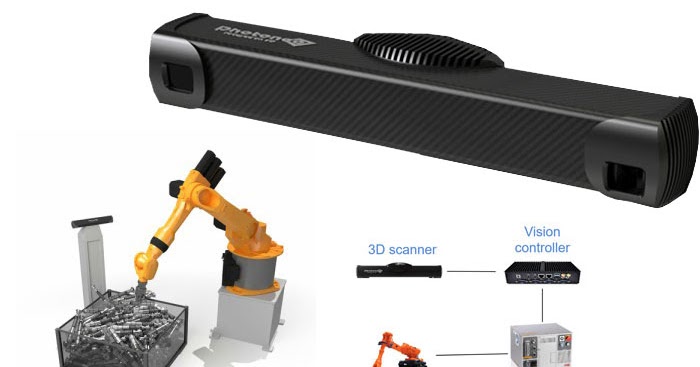
Preparing your Object
- If your object is transparent, reflective, or very dark, you may need to use talc or opaque hairspary to increase scanner accuracy.
- Make sure that any movable parts on your object are made immobile, or their positions marked so they can be returned to their proper location.
- You may also wish to make alignment marks using the alignment pen. These marks will make it easier to place pins and identify locations on the object.
- Place your object in the center of the scanner turntable (AutoDrive). There are various attachments for mounting more delicate objects onto the turntable (PartGripper).
- Use a ruler ensure that the center of the turntable is 17" from the front of the scanner for a normal scan, or 11" for a closeup scan.
- You can also setup the black poster board provided to act as a black background behind your object.
Preparing the Scanner
- Log-in to the MakerLab scanning computer and open the ScanStudio software.
- The blue gear icon at the top of the scanner should light up. If it does not, check the scanner's connections.
- Ensure that the scanner power and USB cables are plugged in at the back of the scanner, and the turntable is connected at the front of the scanner.
- ScanStudio should report that “Your Scanner is Ready,” and the scan button at the top left should be green.
- To use the software environment:
- 3D geometry is shown in the main window.
- A variety of scanning tools are accessed using the top toolbar, which also shows the status of the program.
- The bottom pane is a library of scans in the current file.
- Click the triangular "Scan" button in the main toolbar to enter the scan window. The scanner will brightly illuminate the object for setting up.
- On screen you will see a live video image from the camera in the scanner. Watch this and manually adjust the position of the scanner so that the object is in the center of the on screen preview.
- Do not worry if your object does not fit in the preview at the appropriate distance - you can scan different parts of the object and align them together later.
Running a Single Scan
In most situations you won't be able to capture an entire object with just one scan. Instead, you can scan the object multiple times in different axes. Sometimes this process will be automatic, and sometimes you’ll have to reposition the object and then scan it again. The NextEngine supports three kinds of scanning: 360 scans, bracket scans, and single scans. A single scan is a single pass of the laser over the object. A 360° scan will automatically scan the object through all 360° of travel of the turntable's drive. To perform a single scan:
- Click the green "Scan" icon in the ScanStudio main toolbar.
- A new scan panel will be loaded. Set your scan name in the yellow "Model" field.
- At the top of the scan panel, select "Single Scan.
 "
" - Choose a "Points/in" to set the scan resolution:
- Quick scans are low resolution and may be very crude.
- SD and HD scans are recommended for most objects.
- At the bottom of the page you will see the estimated time that the scan will take.
- Set the target for neutral, dark, or light objects.
- Set the range for your object, either macro for small objects or wide for larger objects.
- Be sure than the object is contained and centered within the scan preview window.
- Click the green "Start" arrow in the top toolbar to begin your scan.
- The scanner will illuminate the object, taking a photo first, then scan a laser array over the object.
- Once the scan is finished, a thumbnail of the scanned surface should appear at the bottom left of the screen. This is what is called a scan 'family'. A full view may also appear in the main window. If not, click on the thumbnail to view the scan.
- To manipulate the completed scan:
- Left click and drag to rotate the scan.
- Right click and drag up and down to zoom in and out.
- Click both left and right buttons and drag to pan.
Running a 360° or Bracket Scan
A 360° scan will automatically scan the object through all 360° of travel of the turntable's drive. To perform a 360 scan:
- Click the green "Scan" icon in the ScanStudio main toolbar.
- A new scan panel will be loaded. Set your scan name in the yellow "Model" field.
- At the top of the scan panel, select "360° Scan" or "Bracket Scan."
- Set the number of divisions for your scan:
- We recommend 12 divisions, which translate to 30 degrees between each scan (360/12=30).
- Choose a "Points/in" to set the scan resolution:
- Quick scans are low resolution and may be very crude.
- SD and HD scans are recommended for most objects.

- At the bottom of the page you will see the estimated time that the scan will take.
- Set the target for neutral, dark, or light objects.
- Set the range for your object, either macro for small objects or wide for larger objects.
- Be sure than the object is contained and centered within the scan preview window.
- You should also ensure that the object is viewable from all angles using the rotation arrows in the toolbar.
- If necessary, select a zoom area. Do so by using your mouse draw a box around the area of interest in the preview window.
- Add markers on your object if necessary:
- If you are planning on making multiple scans, such as to piece together an object too large to fit in one scan, you will need to add some markers to aid in reconstruction.
- Three markers are required for every section to be matched up.
- Attach the markers to your object and ensure they will always be visible to the scanner as the object rotates.
- Click the green "Start" arrow in the top toolbar to begin your scan.
- A full 360 or bracket scan will likely take 30-60 minutes to complete.
- Once the scan is finished, a thumbnail of the scanned surface should appear at the bottom left of the screen. This is what is called a scan 'family'. A full view may also appear in the main window. If not, click on the thumbnail to view the scan.
- Repeat as necessary for large or complex objects. Your aim should be to have all parts of the object represented between all your scan families. Remember that you will need markers to align these scans later.
- To manipulate the completed scan:
- Left click and drag to rotate the scan.
- Right click and drag up and down to zoom in and out.
- Click both left and right buttons and drag to pan.
Processing your Scan Family
In the ScanStudio software, a "scan family" is the name given to the results of a scan operation and are listed in the library at the bottom of the screen. "Attaching" indicates to the software the scan families that you would like to use in building the final mesh of your scanned object.
- Scan families that are already attached are given green background in the scan library at the bottom of the screen. The software automatically attached the first scan family you made. You can detach this scan family by right clicking its thumbnail in the scan library and choosing "Detach" from the context menu.
- Right click the thumbnail of your recent scan family in the scan library and choose "Attach" from the context menu. Scans are labelled alphabetically, so your most recent scan family will always be the one with latest letter alphabetically.
- Bracket or 360 scans are made up of a series of single scans. You can view these individual scans by double clicking the scan family in the library. The library then shows the individual scans.
- You can view each in detail in the main window by selecting individual scans in the library.
- You can also attach and detach individual scans in the same way that you did with scan families.
- Click the return arrow in the scan library to go back to the top level.
Aligning your Scan Family
If you have made multiple scan families, such as when scanning a large object in sections, you will need to align these scan families.
- Select the scan family to align (bottom bar) and click "Align" in the main toolbar.
- Two geometry view windows are now visible. The left side shows you the collection of scans/families that are already aligned. The right side shows you the next scan that you are aligning to that collection.
- If you have not already done so, attach one of your scan families. The software will help you align an unattached scan family with the attached ones.
- Select the scan to align from the right geometry window (blue).
- Use the yellow, red, and blue dots from the top right to mark corresponding spots on each scan.
- As you drop a dot the view will zoom in. You can then move it again for finer placement.
- When all dots are in corresponding places, click "Align" in the main toolbar.
- When the alignment is complete, click "Back" in the main toolbar.
Trimming Unwanted Geometry
The NextEngine scanner will likely pick up some unwanted geometry, such as the hardware restraining your object. You trim this geometry:
- Click "Trim" in the main toolbar.
- Select the areas of mesh you wish to trim. You can do this using the tools in the main toolbar:
- Square/circle brush - use these to draw over the geometry to be trimmed.
- Draw rectangle - use this to draw a rectangle over the areas to be trimmed.
- Draw polygon - use this to draw a polygon over the areas to be trimmed.
- All - select all geometry in the scan.
- +/- - add to or subtract from the selection.
- Continue selecting until all unwanted areas are highlighted.
- Click "Trim" in the main toolbar to delete the selected geometry.
- Repeat this process as necessary until all unwanted areas are removed.
- Click "Back" when you are finished trimming.
Filling Holes in the Geometry
- Select "Polish" from the main toolbar, then click 'Fill."
- The software scans the mesh looking for holes, and highlights them.
- You can then select which ones you would like to fill by using the brush tools (as for trimming).
- Once you have selected the holes you wish to fill, select "Fill."
- The software will attempt fill in the mesh at the holes, with varying success.
- When complete, click "Back" in the main toolbar.
Fusing your Scans
- Click "Fuse" in the main toolbar of ScanStudio.
- Click "Settings" to manage the fuse:
- Be sure to select "Create water-tight model."
- Set resolution to 0.
 9 all other default settings are fine.
- Click "Fuse."
Exporting your Scan
The NextEngine ScanStudio software can export 3D geometry files for 3D printing or editing using CAD programs. To export your scan:
- Click "Output" in the main toolbar of ScanStudio.
- Select "STL" or "OBJ" to save to those filetypes. STL is the more common, however OBJ is often more detailed.
- A save dialog box will open where you can choose a name and location for the exported file. Be sure to check the box to export only your green attached mesh, otherwise Scan Studio will export all meshes superimposed on top of each other.
- Save your NextEngine scan file (.scn) before closing, in case you need to come back to it.
Tutorial Videos
The following tutorial videos will show you how to:
- Scan a simple model (1)
- Select scan settings (1)
- Trim your scans (2)
- Align your scans (2)
- Fuse your scans (2)
- Export your scan (2)
Click on any of the video icons below to begin the selected tutorial.
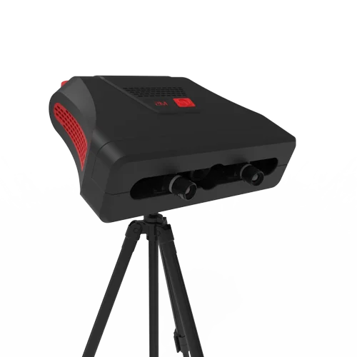
review of the peel 2 CAD-S handheld 3D scanner / Sudo Null IT News Compared to its predecessor, the peel 2, the device boasts higher detail when scanning small objects.
Peel 3d is a trademark of Ametek/Creaform. All of the parent company's knowledge and know-how in 3D scanning and reverse engineering has been invested in making peel 3d products more accessible to reach a different target audience.
The peer 2 scanner proved to be very functional and useful in many applications, but it lacked the ability to capture the finer details of objects. Consider the new peel 2 CAD-S model to evaluate the changes that have taken place.
peel 2 CAD-S uses the same structured white backlight technology as the previous model, but with higher resolution and therefore better suited for working with smaller elements.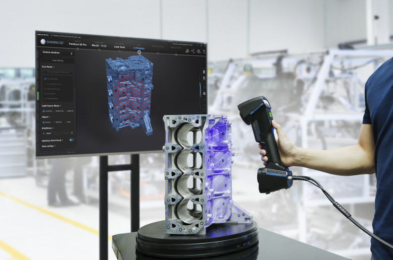 The recommended part size is less than 0.5 m (for comparison, for peel 2 - from 0.3 to 3 m).
In practice, this means that when using the same sensors and cameras, the scan area is reduced from 380 x 380 mm to 142 x 108 mm. Essentially, you get the same number of pixels in a much smaller space, so peel 2 CAD-S can capture 3D shapes at 0.1mm grid resolution – in other words, five times more accurate than peel 2.
Setup and first use 3D Scanner
The setup process is almost the same as for all other 3D scanners. The whole set comes in a regular case with a foam insert: a scanning device, software and a license key on a USB stick, as well as a switch. The cables are designed for power (from a standard power supply) and data transfer (via Hi-Speed USB 2.0). The installation process is simple: insert the flash drive into your computer, run the installation and follow the suggested steps.
For hardware requirements, you'll need a modern workstation or laptop with an Nvidia GPU and at least 2 GB of VRAM. Processor - the faster the better, but because the system is geared towards small parts, the chances of overloading a modern processor are minimal.
Calibration must be performed after installation. Calibration of this type of device is not difficult, and the general recommendation is that it should be done fairly regularly, especially as the conditions in which the scanner is used change. This may be due to light (for example, moving to another office, to another area of \u200b\u200bthe shop or workshop) or temperature. After the calibration is completed, the device is ready for use.
When the peel 3d software is launched for the first time, the user is presented with two main options. You can follow the help guide that will guide you through the entire 3D scanning process, determining how to capture the object, what resolution and positioning methods to use (geometry, texture, or position labels), and help you with your work. Another option is to do the setup yourself.
First you need to define the scan resolution. The default is 1.0 mm, but values from 0.1 mm to 2.0 mm are possible. The lower the value and the sharper the resolution, the better the scan and the larger the dataset. Given that peel 2 CAD-S is designed for small objects with fine detail, a good GPU can easily handle even 0.1mm resolution.
The next step is to set how the system will track the movement of the 3D scanner around the object. As with other similar devices, there are three options: texture, geometry, and labels. Structured light scanners equipped with texture capture can use the surface texture to track the movement of the scanner/object. peel 2 CAD-S can also use object geometry. Both of these methods work well for organic shapes and textured objects.
Regularly shaped products with uniform surfaces (most often mechanical parts) may require the use of position marks.
These are small, custom-sized reflective markers that can be stuck on or around an object. They are used to determine the position of the scanner in relation to the object using triangulation methods. As long as there are three marks in the field of view of the 3D scanner at the same time, this method usually gives a good result and ensures correct tracking of the scanner.
The peel 2 CAD-S kit includes a set of small plastic jigs with three marks that can be placed around the object for quick adjustment. These devices are very useful considering that the device is focused on digitizing small details with high detail, and sticking several 4mm marks on them is not a very practical solution. The
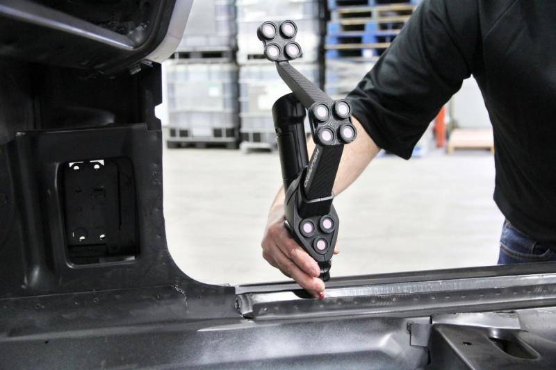
peel 2 CAD-S is designed for high-resolution scanning of physical objects, and many of its features are based on proven Creaform 9 designs.0014 Scanning process 3D scanning typically involves collecting as much data as possible in one position. The device is quite light and well balanced, which many competitors' products cannot boast of. The function of determining the distance to the object (ideally 300 mm) with color indication on the screen and on the device itself allows you to scan very quickly.
It is worth noting that the peel 3d software provides a very rough preview. Since the scanner usually collects a huge amount of data, it makes sense to gradually filter it out as you work.
As you get used to the operation of the device and get used to quickly moving the scanner around an object (or quickly rotating a part on a turntable), you will understand how to maintain continuous tracking. At any time, you can take your finger off the shutter, pause the scan and review the data, and then return to digitizing the missing areas.
There are two paths after the initial scan. If there is enough data, then you can start the cleaning process and remove excess data. There are a number of tools available for this and the procedure is quite simple - this is one area where all the investment in Creaform know-how is worth it. Then the meshing and further cleaning is performed.
Otherwise, especially for complex parts, a more thorough rescan may be required. This repeats the same process, resulting in two or more data sets that need to be matched. Once again, Creaform's knowledge and technology comes into play, allowing you to use common dots (you must select three common dots between two or more images) to combine multiple scans.
After the scan (or set of scans) is ready, the next step is to prepare for data post-processing. You may just need to create a mesh, fill holes, and export the data to OBJ or STL format. In this case, the available tools will help smooth surfaces, remove noise and fill in all holes to ensure reliable export.
You may also need to build analytical surfaces from the point/mesh data, either to get a point of reference to reuse the mesh in CAD (surfaces allow you to align and reassemble the model) or to create reference geometry to build a more complete model.
The peel 3d software is not really designed to build a fully sealed solid model. Its purpose is to help build a set of reference surfaces that are consistent with point and grid data. This view of the scanned data can be imported into a full-featured 3D design system and the 3D model can be completed.
Although it may seem a little complicated, in fact, in most cases, other surfaces (such as cylinders, spheres, planes) can be added to the prismatic model almost instantly etc.).
These surfaces and points can then be loaded into CAD. This usually requires two exports: first a mesh data file in STL or OBJ format, then a surface data file in STEP or IGES format (for example). The result should be a set of two types of geometry that can be used to build the required model.
Conclusions
At first glance, the peel 2 3D scanner makes a strong impression. Relatively low price, excellent build quality and, last but not least, reliable and simple software. The main problem was that it is not suitable for those who require higher resolution scans. The
peel 2 CAD-S takes the same approach as its predecessor but focuses (both literally and figuratively) on smaller objects and capturing finer details while maintaining the same ease of use when combined with software by Creform.
The resulting scans are of excellent detail, and by mastering the art of multiple scans, stitching and alignment, as well as the practicalities of working with reflective surfaces, you can achieve impressive results.
peel 2 CAD-S and peel 2 complement each other perfectly, and it makes sense to have both scanners at the workplace. In practice, this option is very common. If you are interested in 3D scanning solutions, the peel 3d line deserves a deeper look.
Source: Develop3d.com
Select 3D scanner: Types, advantages, Tasks for
3D scanners
Fundamentals 3D
Reverse Engineering
Geometry Control
The best according to
Automation Automation Automation quality control
Author: Semyon Popadyuk
Author: Semyon Popadyuk
Benefits of 3D Scanners | What tasks does 3D scanning solve | Criteria for choosing a 3D scanner | Professional 3D scanning for fast and efficient production solutions
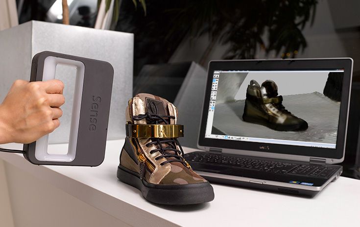
Modern 3D scanners have a wide range of features and a variety of functionality. They are used everywhere - in manufacturing, construction, education, entertainment and are used even in everyday life. In order to choose a scanner that meets your needs, there are a number of aspects to consider, which we will discuss in this article.
Order a free test 3D-scan using the equipment of the world's leading manufacturers:
Leave a request
Benefits of 3D Scanners
What is a 3D scanner? This is a device designed to quickly analyze a physical object and create its accurate 3D computer model. The principle of its operation is based on calculating the distance to the object using two cameras. In addition to the cameras, a backlight is used - LED or laser.
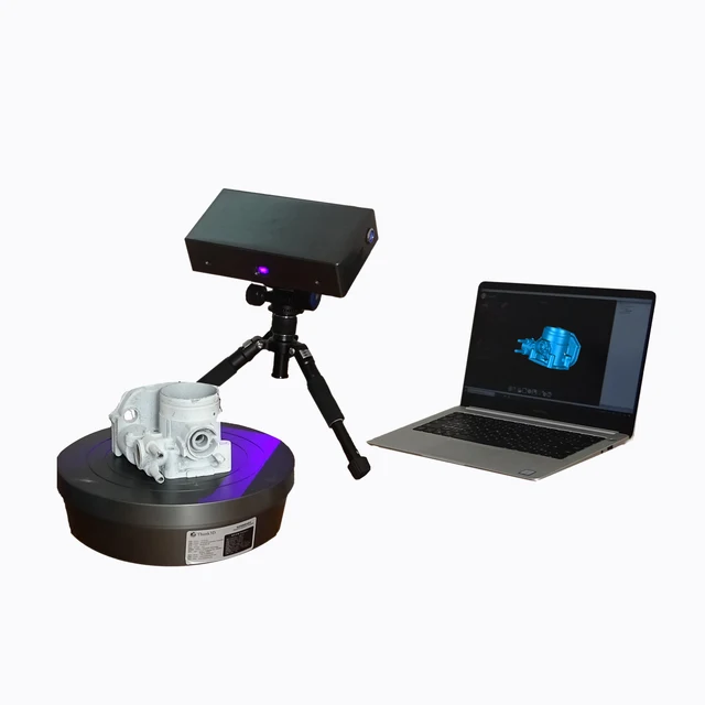
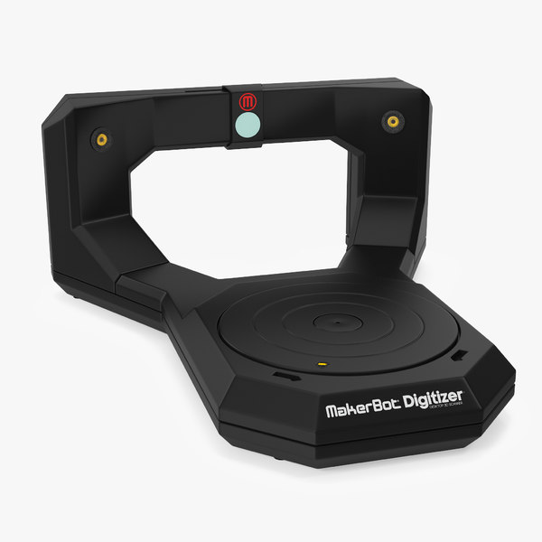
3D scanners are classified both according to their form of execution (stationary and portable) and according to the areas of use, mainly divided into professional and household.
3D scanners make it possible to significantly reduce the time and costs at the development stage, improve the quality of products and, ultimately, speed up the release of the product to the market. They can be used at any stage of product lifecycle management and will help to optimize the production process of enterprises in various industries, including:
- automotive,
- mechanical engineering,
- aerospace industry,
- oil and gas industry,
- shipbuilding,
- building and architecture,
- arts and culture,
- medicine,
- jewelry,
- science and education.
3D scanning devices remove many of the limitations of traditional measuring equipment. Such tools familiar to the metrologist as templates, micrometers, calipers are inexpensive, but they are characterized by subjective readings and are not suitable for complex measurements. Coordinate measuring machines are more accurate than 3D scanners, but they are more expensive, larger, and require specialized operator training.
Optical inspection systems, which include 3D scanners, are the best solution in terms of price and quality, as they provide:
- measurement speed,
- high accuracy of digitizing objects of complex geometry,
- can work autonomously,
- are easy to operate.
Thanks to a 3D scanner, the work of a designer, technologist, and constructor is greatly facilitated: the performance of time-consuming complex measurements and the creation of a design from scratch are a thing of the past.
What tasks does 3D scanning solve
- Quality control: the ability to check any geometric parameters, including input and output control, metrological control of parts and production equipment.

- Reverse engineering of products for prompt receipt of project documentation and product upgrades.
- Design and simulation for the purpose of prototyping and evaluation of the appearance of products, modernization of production facilities and equipment.
- Digital archiving of any required assortment (eg discontinued parts). Models stored in digital libraries are available remotely from anywhere in the world.
3D scanner selection criteria
The main criterion is scanning accuracy . High-precision devices (10-30 microns) will help to get a phenomenal result: they are able to transfer the most complex surface geometry into 3D with minimal errors. Such 3D scanners are used in reverse engineering, quality control, medicine, and are used to digitize molds, device parts, etc. 3D scanners with an accuracy of 30–100 engineering.
ZG AtlaScan is the world's first 3D scanner with hole capture
When choosing a 3D scanner, you should also consider resolution (detail) , i. e. the degree of discreteness that is available when digitizing an object. The highest level of detail allows you to display the smallest elements in the 3D model.
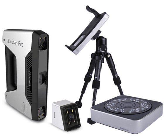
Р the size of the scanned objects and, accordingly, the mobility of the 3D scanner are directly dependent on the type of device you select. When digitizing details and objects of small and medium parameters, hand-held scanners are usually used. Stationary scanners are suitable for capturing complex small and medium-sized products with fine details. Scanning of large objects (buildings, structures, communications) is performed using ground-based laser devices (rangefinders).
When studying the functionality of 3D scanners, pay attention to such points as the conditions of use, scanning speed, the surface of the scanned object, and color.
Please note that the next step after scanning is to obtain and further work with the CAD model, and for this you will need specialized software.
Processing 3D Scan Data for Reverse Engineering in Geomagic Design X Software
Professional 3D scanning for fast and efficient production solutions
iQB offers cutting-edge solutions that successfully operate in leading enterprises around the world:
- Portable devices for metrological 3D measurements from ZG Technology (China). The line includes a wide range of instruments, from an affordable handheld 3D scanner to a powerful optical tracking measurement system, as well as photogrammetry and portable CMM. ZG's unique strengths include the world's first handheld MarvelScan solution with three cameras for markless laser scanning and tracker, and proprietary instant hole capture technology. ZG Technology 3D scanners provide measurement speed up to 1 million 350 thousand points per second and accuracy up to 0.01 mm.
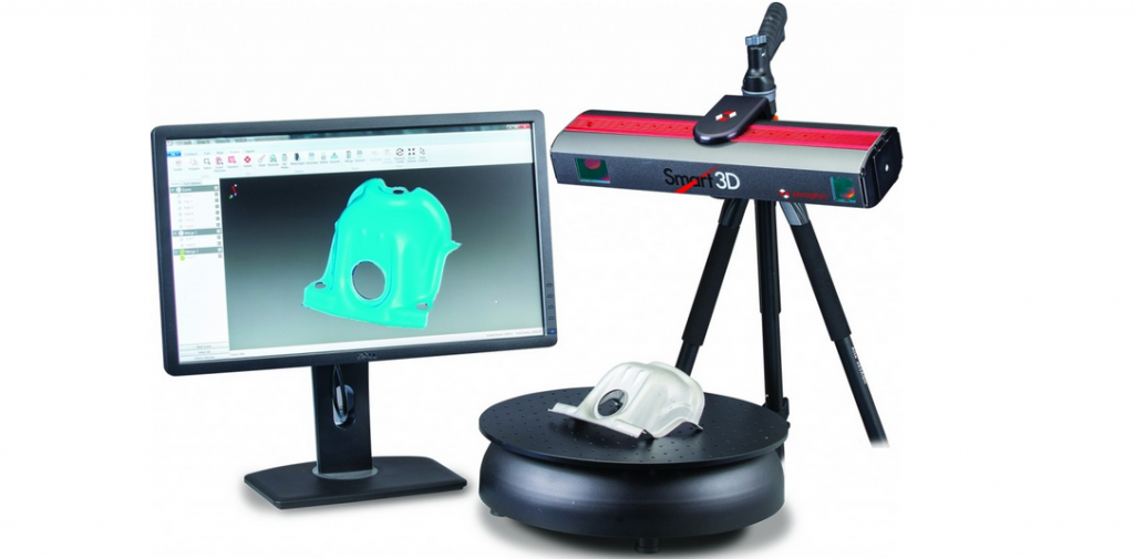
- Stationary Russian-made RangeVision PRO 3D optical scanner is an industrial solution for metrology, available to companies of any level.
 The device is designed to digitize objects from 1 mm to 5 m and offers the highest level of accuracy (up to 0.018 mm) and 3D resolution (up to 0.04 mm). This is the first domestic 3D scanner approved by the Federal Agency for Technical Regulation and Metrology as a type of measuring instrument.
 - Creaform handheld 3D scanners for digitizing products ranging in size from a few centimeters to 6 meters. The Go!SCAN series devices (including the latest Go!SCAN SPARK) are based on structured illumination technology; HandySCAN 3D and MetraSCAN 3D are laser devices that are certified industrial grade metrology tools. The new generation MetraSCAN BLACK|Elite model is the fastest handheld 3D laser scanner on the market (1.8 million measurements per second). The volumetric accuracy that Creaform technology can provide is up to 80 microns per 16 cc.
 m.
m. - Creaform also produces 3D scanners and software under the peel 3d brand, combining affordability, ease of use and high quality. The line is designed to solve the problems of reverse engineering and digitalization of objects in such areas as art, preservation of cultural values, consumer goods, science and education, human body scanning. Peel 3d devices are capable of measuring objects from 0.3 to 3 m with an accuracy of 0.1 mm.
RangeVision PRO Fixed Scanner Creates Yamaha R3 Sport Fairings with Improved Aerodynamics, High Strength and Lighter Weight
- Solutionix fixed optical 3D scanners for small objects (10-500mm) with many small parts. Allow to receive an error less than 8 microns.
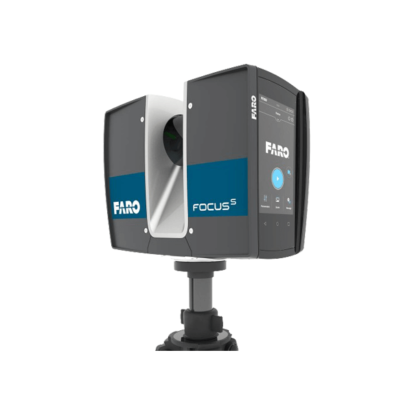
- FARO Focus 3D geodetic laser scanners perform fast and accurate scanning of large objects, complex structures, premises and landscapes. They operate in the range from 0.6 to 350 m, they are distinguished by increased accuracy, ease of operation and the ability to operate in the most difficult environmental conditions.
- EPiC budget 3D terrestrial laser scanners are based on the principles of simplicity, convenience and affordability.
 Their main advantages are super light weight, high shooting speed (from 30 to 90 seconds), 360-degree panoramic camera and the ability to control from a mobile device.
Many of the above scanners are included in the register of measuring instruments of the Russian Federation and have the appropriate certificates.
Robotic 3D scanning systems, such as Creaform MetraSCAN 3D-R, allow you to increase the speed and efficiency of quality control directly on the conveyor
A variety of 3D scanning devices on the market will allow you to choose exactly the model that is needed for solving specific problems. The price range is also wide: from simple devices costing up to $500 to high-precision professional 3D scanners costing tens and even hundreds of thousands of dollars.
Contact iQB Technologies experts! We will select the optimal solution that will optimize product development and production in your enterprise, design office or research center.