3D printed anemometer
HowTo: Anemosens - Build a 3D printed wind sensor / anemometer - Nerdiy.de
To be honest, the idea of a 3D printable wind sensor (in technical jargon “anemometer”) has been floating around in my head for a long time.
Initially I could have used it as a wind sensor for one of my weather stations. At that time I had an FDM 3D printer available and also a few first ideas for a printable design.
I then printed out the design shown on the left and tested it.
Unfortunately, this design never made it past the prototype phase. The limitations of the FDM printing process were somewhat problematic here. Especially when printing overhanging structures, the tolerances were often so bad that the parts didn’t fit together properly.
So I put the project on hold again. But when I started developing the second version of a 3D printable wind turbine, the topic of an anemometer came back to my desk. This time I wanted to build a wind turbine with electronic wind tracking. That means WinDIY_2 (that’s the name of the wind turbine) should not get a wind vane, which automatically aligns the nacelle to the wind. Instead, the nacelle should be turned into the wind via a servomotor. In order for this to work, the electronics must of course know the current wind direction. Of course, this only works if the electronics are able to measure the current wind direction. You probably already know where this is going: This is how the idea was born (again) to design a 3D printable anemometer.
At this time my “machine park” had already grown a bit. In addition to my FDM printer, I could now also use an SLA printer. The practical thing about this is that with SLA printers you can also print overhanging structures very well and generally in a much higher resolution than with FDM printers. From the production side, almost all concerns were resolved. 🙂
So the anemometer had to be as compact as possible, because unnecessary weight should be avoided at this point (and because it just looks cooler.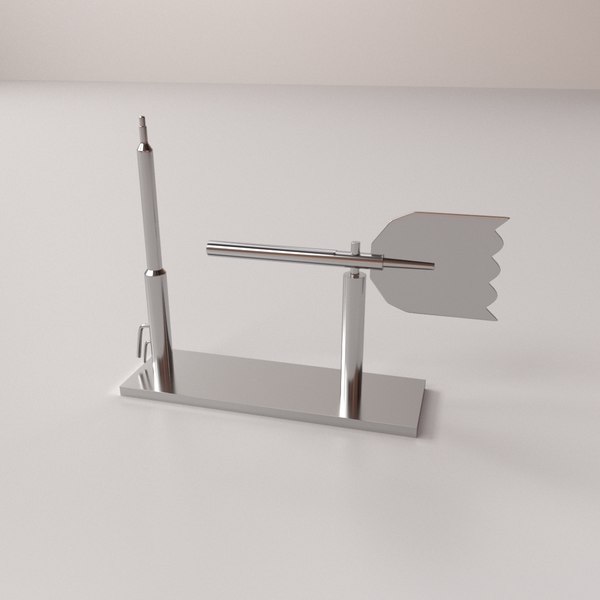 🙂 )
🙂 )
For integration into WinDIY_2, the anemometer should be mounted on a small boom on the nacelle of the wind turbine.
The first draft still looked like shown in the photo. A bit “plump” and still with a detachable tip.
All in all unfortunately still a bit too big for the design of WinDIY_2. So I went back to the desk.
After a few more drafts, the design shown on the left eventually came out.
A very compact anemometer with the following data:
- Base diameter: 27mm
- Rotor diameter: 150mm
- Height (incl. base): ~160mm
This design consists of a few parts which can be printed out on a standard SLA printer.
Cross-sectional view of anemosens.In order to be able to evaluate the measured values for wind speed and wind direction, I created a small sensor board, which can be integrated into the base in such a way that the sensors are positioned in exactly the right places. The sensor board can then be connected to an ESP32 via an optional additional board (the Anemosens_MCU PCB). The data can then be further processed or stored in various ways.
Various interfaces and an SD card slot are available on the Anemosens_MCU circuit board. Further information about this board can also be found under the following link.
- PCB – Build Anemosens_MCU PCB
The general structure of Anemosens is described in the following article.
The following gallery also contains a few pictures of the circuit boards used and the general structure.
You can see more information in the following video.
This video also shows the structure of the anemosens sensor PCB.Inhalte
- 1 Safety instructions
- 2 Affiliate links / advertising links
- 3 Requirements
- 4 Build the sensor board
- 4.
 1 The wind direction sensor
 - 4.2 The wind speed sensor
- 4.3 PCB manufacturing
- 4.
- 5 Gather the required materials
- 6 Prepare magnet holder
- 7 Insert ball bearings into the components
- 8 Assemble the prepared parts
- 9 Insert the sensor board into the socket
- 10 Assemble the case with the base
- 11 Optional: Build the Anemosens_MCU board
- 12 The Anemosens_MCU firmware
- 13 Have fun with the project
- 13.1 Share this:
- 13.2 Like this:
Safety instructions
I know the following hints are always a bit annoying and seem unnecessary. But unfortunately, many people who knew it "better" from carelessness lost their eyes, fingers or other things or hurt themselves. In comparison, a loss of data is almost not worth mentioning, but even these can be really annoying. Therefore, please take five minutes to read the safety instructions. Even the coolest project is worth no injury or other annoyance. https://www.nerdiy.de/en/sicherheitshinweise/
Affiliate links / advertising links
The links to online shops listed here are so-called affiliate links. If you click on such an affiliate link and shop via this link, Nerdiy.de receives a commission from the online shop or provider concerned. The price doesn't change for you. If you do your purchases via these links, you will support Nerdiy.de in being able to offer further useful projects in the future. 🙂
Requirements
For the construction you have to master soldering tasks. The following articles provide tips on how to do this.
- Electronics – My friend the soldering iron
- Electronics – Solder THT components by hand
- Electronics – Solder SMD components by hand
Required tools:
| Quantity | Item | Link |
|---|---|---|
| 1x | soldering iron | Bei Amazon kaufen |
| 1x | USB soldering iron | Bei Amazon kaufen |
| 1x | third-hand | Bei Amazon kaufen |
| 1x | soldering tip cleaner | Bei Amazon kaufen |
| 1x | hot glue gun | Bei Amazon kaufen |
| 1x | SLA 3D printer | Bei Amazon kaufen |
| 1x | M2 internal tap | Bei Amazon kaufen |
| 1x | M3 internal tap | Bei Amazon kaufen |
| 1x | M8 internal tap | Bei Amazon kaufen |
| 1x | M8 external tap | Bei Amazon kaufen |
| 1x | Torx screwdriver | Bei Amazon kaufen |
Required material:
| Quantity | Item | Link |
|---|---|---|
| 1x | M2x6 grub screw | Bei Amazon kaufen |
| 6x | M2x6 countersunk screw | Bei Amazon kaufen |
| 3x | M3x6 grub screw | Bei Amazon kaufen |
| 1x | M3x50 countersunk screw | Bei Amazon kaufen |
| 6x | M2 threaded insert | Bei Amazon kaufen |
| 3x | M3 thread insert | Bei Amazon kaufen |
| 3x | Cylinder magnet 5x2mm | Bei Amazon kaufen |
| 1x | Cylinder magnet 10x5mm | https://www. supermagnete.de/scheibenmagnete-neodym/scheibenmagnet-10mm-5mm_S-10-05-DN supermagnete.de/scheibenmagnete-neodym/scheibenmagnet-10mm-5mm_S-10-05-DN |
| 1x | 623 ball bearings | Bei Amazon kaufen |
| 2x | 608 ball bearings | Bei Amazon kaufen |
| 1x | JST SH connection cable | Bei Amazon kaufen |
| 1x | 3D printer resin | Bei Amazon kaufen |
| 1x | Glue | Bei Amazon kaufen |
| 1x | 10x2mm aluminum tube | Bei Amazon kaufen |
| 1x | solder | Bei Amazon kaufen |
| 1x | USB power supply | Bei Amazon kaufen |
| 1x | USB-C cable | Bei Amazon kaufen |
Build the sensor board
An important component for recording the wind data is the Anemosens sensor board. A Hall sensor and an AS5048B (a “magnetic rotary encoder”) are installed on it. The wind speed is measured with the Hall sensor. The wind direction is measured with the AS5048B.
You can find more information about the sensor board in the following article.
- PCB – Build the Anemosens sensor PCB
The structure of the circuit board can be seen very well in the following video from the 50th second.
Wiring of the anemoses sensor PCBThe wind direction sensor
The AS5048B sensor can be read via the I2C bus. A number of degrees from 0-360° is output. The resolution of the AS5048B is 14 bits which corresponds to 0. 0219°. In order to assign the number of degrees to a compass point, the sensor must of course be aligned or calibrated appropriately.
More info on the AS5048B is available here: https://ams.com/en/as0548b
The wind speed sensor
The wind speed is evaluated using an Ah59E Linear Hall Effect Sensor. This detects the passing of the three magnets built into the rotor. Every time one of the magnets passes the sensor, this can be measured as a change in the analog output voltage of the sensor. For reasons of symmetry, three magnets are installed in the rotor. This means that the number of pulses detected must be divided again by three in order to be able to determine the time for one revolution. This number of revolutions can in turn be used to determine the wind speed. For exact readings, you should calibrate the measured value with a real wind speed.
PCB manufacturing
You can find all the information you need to manufacture the PCBs here:
- https://www.
pcbway.com/project/shareproject/Anemosens_sensor_PCB.html
You can see a good overview of which components belong where on the PCB in the following paragraph. Thanks to the work of the Open Scope Project, you can generate very helpful HTML files in which you can see directly which components have to be installed where on the PCB.
You can see the overview for the Anemosens sensor PCB here: Anemosens Sensor-PCB
You can also find the current file in the GIT repository under the following link:
- https://github.com/Nerdiyde/Anemosens/blob/main/PCB/anemosens_sensor_pcb_v1.1_bom.html
(Please note that you have to download the HTML file to view it. This is not possible directly from the GIT repository.)
Gather the required materials
Before you can start you should of course collect all the required individual parts.
The STL files for 3D printing the required parts can be found in the Anemosens Git Repository at:
- https://github.
com/Nerdiyde/Anemosens/tree/main/STLs
You will need the following parts for assembly:
- 1x M2x6 grub screw
- 6x M2x6 countersunk screw
- 3x M3x6 grub screw
- 1x M3x50 countersunk screw
- 6x M2 thread insert
- 3x M3 thread insert
- 3x cylinder magnet 5x2mm (diameter: 5mm, height: 2mm)
- 1x cylinder magnet 10x5mm (diameter: 10mm, height: 5mm) diametrically magnetized!
- 1x 623 ball bearing
- 2x 608 ball bearings
- JST SR connection cable
- The 3D printed parts
In the following, the required individual parts are shown again in the gallery view.
In this example, the 2x5mm magnets are already installed in the designated pockets in the rotor.
Simply place the magnets in the pockets and close the openings with some glue.
Prepare magnet holder
The magnet holder holds the 10x5mm cylinder magnet just above the AS5048B sensor. It is rotatably connected to the wind vane via the M3x50mm screw. In this step you should prepare the magnet holder.
You will need the parts shown on the left.
First place the M3x50 screw as shown and screw it into the bracket as far as it will go.
If the screw is difficult to screw in, you should cut the hole clean again with an M3 tap.
Then screw in the M3x50 screw as far as it will go.
Another view of the screwed-in M3x50 screw.
Now you can glue the 10×50 cylinder magnet into the holder.
To do this, put a small drop of glue in the holder and then press the magnet into the holder.
Caution: Note that this magnet must be a diametrically magnetized magnet. Otherwise the AS5048B cannot detect the rotation.
The cylinder magnet should then sit flush in the bracket.
Insert ball bearings into the components
Before you can continue assembling the rest of the components, you should first prepare them. In this step, the ball bearings are inserted into the 3D printed parts.
Before you do that, however, you should first free all ball bearings from their bearing grease and replace them with smooth-running machine oil. Manufacturers often supply ball bearings coated with bearing grease. This is actually useful to protect the bearing parts from corrosion and to keep them running smoothly. Unfortunately, this also increases the initial torque and resistance to rotation.
In order to keep this as low as possible, you have to remove the sluggish bearing grease. So that the bearing is still protected against corrosion afterwards, you should then conserve the bearing with machine oil (as is known from sewing machines, for example).
You can then use the bearings prepared in this way to assemble the bearing.
To do this, insert the first of the 608 ball bearings into the rotor.
The bearing should then …
… sit flush. You don’t have to fasten it any further at this point.
You can then insert the other 608 ball bearing into the holder in the wind vane.
This is just a test to see if everything fits properly. You then have to remove the bearing from the holder in the wind vane again.
So put the bearing straight on the bracket…
… and push it in until it…
… sits flush in the bracket.
At this point you can already fix the bearing with the M2x6 grub screw.
If necessary, you should first recut the thread with an M2 tap.
Another view.
You can then simply attach the remaining 623 ball bearing to the M3x50 countersunk screw of the magnet holder.
Another view.
Assemble the prepared parts
You can then assemble the parts prepared in the previous step.
You will need the parts shown for this.
First place the rotor with the ball bearing on the axis of the base…
…until the rotor sits on the axle as shown.
Then put the spacer ring shown on the axle.
At this point at the latest you have to remove the 608 bearing from the holder in the wind vane.
Then place this bearing on the axis of the base as shown.
And then bolt the bearings with the lock nut shown.
Important: Do not work here with too much force / torque! If necessary (definitely recommended depending on the print quality) you should re-cut the M8 external and internal thread with a tap!
Then unscrew the lock nut until the ball bearings are securely seated on the main axle.
Now you can put the wind vane back on the previously attached 608 ball bearing…
… and and fix it …
… with the M2x6 grub screw.
In the last step, the magnet holder is connected to the wind vane.
To do this, you should (only) wet the tip of the M3x50 countersunk screw with some screw locking varnish.
Here it is important that some screw locking varnish arrives in the thread in the wind vane. If necessary, you can also remove the wind vane again and drip the locking paint directly into the threaded hole. In any case, make sure that no locking paint gets into the ball bearings.
View of the opening into which the magnet holder must be inserted.
Then place the magnet holder in such a way that the attached 623 ball bearing slides into the pocket provided. Then hold the magnet holder and turn the wind vane at the same time until the M3x50 screw grabs the thread in the wind vane and is screwed in all the way.
You can also see the entire process in this video from second 95 onwards.
Completely screwed, the fully assembled magnet holder should sit in the base as shown.
Insert the sensor board into the socket
Now that you’ve built most of the sensor housing, you can start building the base.
You will need the items shown on the left for this.
The M2 and M3 thread inserts are already inserted in the socket.
To do this, the M2 were melted into the holder from above and in the upper row from the outside.
The M3 thread inserts are melted into the bottom row of the externally accessible holes.
Another view of the melted-in thread inserts.
In the top row, the M2 inserts are inserted.
In the bottom row the M3 inserts.
Now you can plug the JST SH connection cable into the socket on the sensor housing.
Then push the cable of the prepared sensor board through the hole in the base…
… and screw the circuit board to the base with the M2x6 countersunk screws as shown.
Assemble the case with the base
In the last step you only have to connect the socket to the rest of the housing.
To do this, slide the socket into the base of the sensor as shown.
Then line up the holes in the base with the holes/threaded inserts in the base…
…and screw the base to the base using the three M2x6 countersunk screws.
If desired, you can also insert a 10mm (outer diameter) tube into the base at this point…
…and fix it with…
… the M3x6 grub screws.
Completeöy assembled your anemosens should now look like this. 🙂
What is still missing is the connection to a suitable MCU, which then has to evaluate and process the sensor signals.
Optional: Build the Anemosens_MCU board
The Anemosens MCU circuit board is not absolutely necessary for the operation of Anemosens. You can also evaluate the sensors on the sensor board with your own hardware.
With the help of the Anemosens MCU circuit board, you have the option of reading out the sensor data and sending it via the USB-C connection, Modbus, Wifi or Bluetooth for further evaulation. Optionally, the data can also be stored on a µSD card inserted in the µSD card slot. The data can then be logged with a time stamp via the integrated and battery-buffered real-time clock. The board can also be equipped with a BME280 for further monitoring of the environmental data. Temperature, humidity and air pressure can also be logged.
You can find more information about the Anemosens_MCU board in the article
- PCB – Build Anemosens_MCU PCB
PCB manufacturing: You can find all the information you need to manufacture the PCBs here:
- https://www.pcbway.com/project/shareproject/Anemosens_MCU.html
A simple way to get a good overview of which components are placed where on the PCB is shown in the following paragraph. Thanks to the work of the Open Scope Project, you can generate very helpful HTML files in which you can see directly which components have to be installed where on the PCB.
You can see the sens sensor PCB here: Anemosens_MCU PCB
You can also find the current file in the GIT repository under the following link:
- https://github.com/Nerdiyde/Anemosens/blob/main/PCB/anemosens_mcu_v1.
3_bom.html
(Please note that you have to download the HTML file to view it. This is not possible directly from the GIT repository.)
The Anemosens_MCU firmware
A first version (Work in progress) of an Arduino-compatible software for evaluating the sensor data can be found under the following link.
- https://github.com/Nerdiyde/Anemosens/tree/main/software/anemosens_mcu
This software is tailored for use with the Anemosens_MCU hardware. In this way, the data can be measured, processed and stored. They are also made available (if desired) via the serial interface (via USB), via the Modbus interface, via WiFi or via Bluetooth.
The firmware is compatible with the Arduino IDE and can be transferred to the used microcontroller.
You can find tips on how to program a microcontroller with the Arduino IDE in the article
- ArduinoIDE – Tips and Tricks
Have fun with the project
I hope everything worked as described. If not or you have any other questions or suggestions, please let me know in the comments. Also, ideas for new projects are always welcome. 🙂
P.S. Many of these projects - especially the hardware projects - cost a lot of time and money. Of course I do this because I enjoy it, but if you appreciate it that I share these information with you, I would be happy about a small donation to the coffee box. 🙂
Like this:
Like Loading...
Oklahoma scientists use 3D printing to make low-cost weather station
0Shares
A team of students and researchers from the University of Oklahoma and Argonne National Laboratory have used 3D printing to produce a low-cost weather station.
The design was based on open-source plans developed by the University Corporation for Atmospheric Research as part of the 3D-Printed Automatic Weather Station (3D-PAWS) Initiative and features over 100 additively manufactured components. Putting the weather station to the test in Oklahoma, the scientists compared its efficacy and durability to that of a commercial-grade station over the course of eight months, with promising results.
Adam Theisen, Atmospheric and Earth Scientist at Argonne and lead author of the study, states: “I didn’t expect that this station would perform nearly as well as it did. Even though components started to degrade, the results show that these kinds of weather stations could be viable for shorter campaigns.”
The 3D printed weather station. Photo via Argonne National Lab.What are weather stations used for?
Weather stations comprise various instruments and sensors designed to monitor the factors that influence weather forecasts, including temperature, humidity, wind speed, and solar radiation. As well as being a great tool for news channels, weather stations also facilitate research in fields such as agriculture and renewable energy utilization.
Unfortunately, commercial devices can cost several thousand dollars to produce, limiting their accessibility when funding is at a premium. This is where 3D printing comes in, potentially enabling organizations to cut costs down to the sub-$1000 range, all while bringing manufacturing capabilities to remote locations where spare part sourcing may prove difficult.
The 3D printed weather station
Seeing as the device would be subjected to the harsh environmental conditions of the outside world, the team opted for ASA as the 3D printing material to complement the station’s low-cost sensors. Impressively, the weather station functioned for a full five months before the humidity sensor corroded, and some of the 3D printed parts showed signs of degradation. As a whole, however, the 3D printed frame did hold its own, despite facing rain, snow, and temperatures in the range of -10°C to 40°C.
When it came to performance, the station’s measurements were reportedly comparable to those of a commercial-grade device in the Oklahoma Mesonet, which is a network of environmental monitoring stations. The device’s sensors were perfectly capable of measuring temperatures, precipitation, UV exposure, and humidity accurately. The only instrument that delivered lackluster results was the 3D printed anemometer, which is used to measure wind speeds, as it suffered from low printing quality.
The project ultimately proved that a 3D printed weather station can indeed provide a cost-effective alternative, both in terms of initial start up costs and maintenance costs, to other well-established weather monitoring devices. Theisen concludes: “If you’re talking about replacing two or three of these inexpensive sensors versus maintaining and calibrating a $1,000 sensor every year, it’s a strong cost-benefit to consider.”
This 3D printed UV index sensor used a plastic covering made from a freezer meal tray. The glue had yellowed by the end of the experiment. Photo via Argonne National Lab.Further details of the study can be found in the paper titled ‘More science with less: evaluation of a 3D-printed weather station’. It is co-authored by Adam Theisen et al.
This certainly isn’t the first instance of 3D printing being employed in the development of eco-monitoring devices. Earlier this year, the French National Research Institute for Development developed a water pollution sensor for the wild using Formlabs’ SLA 3D printing technology. The primary objective of this project was to produce a ‘low-cost’ device for environmental monitoring purposes. The team had decided on 3D printing as they wanted to manufacture a user-friendly prototype of the sensor with commercially available tools.
Elsewhere, researchers from the Oak Ridge National Laboratory recently 3D printed a first-of-its-kind smart wall called ‘EMPOWER’, which features weather monitoring capabilities. Built to highlight 3D printing and designed for indoor use, EMPOWER combines concrete additive manufacturing and integrated electronics to serve as a room’s cooling system.
Subscribe to the 3D Printing Industry newsletter for the latest news in additive manufacturing. You can also stay connected by following us on Twitter and liking us on Facebook.
Looking for a career in additive manufacturing? Visit 3D Printing Jobs for a selection of roles in the industry.
Featured image shows the 3D printed weather station. Photo via Argonne National Lab.
Tags Adam Theisen Argonne National Laboratory Oklahoma Mesonet University Corporation for Atmospheric Research University of Oklahoma
Kubi Sertoglu
Kubi Sertoglu holds a degree in Mechanical Engineering, combining an affinity for writing with a technical background to deliver the latest news and reviews in additive manufacturing.
3D printed devices communicate without batteries | Computer world
The energy of the coil spring drives the gear system, and the width and shape of the teeth determines how long the backscatter switch will contact the antenna, generating echoes that can be decoded
Source: Mark Stone/University of Washington
The plastic plug-in devices developed by American researchers use backscattering technologies.
Researchers at the University of Washington have developed a 3D-printed series of plastic plug-in devices that communicate with Wi-Fi receivers without electronic hardware.
The devices use backscattering technologies - when transmitting zeros and ones, external Wi-Fi signals are either absorbed or reflected.
Thereafter, the information contained in the reflected patterns can be decoded by the Wi-Fi receivers.
“Our goal was to create some devices that can be printed on a home 3D printer, with the help of which it would be possible to transfer useful information to other devices,” said Vikram Ayer, a representative of the research team, from the Department of Electrical Engineering at the University of Washington. - The main question was how to organize a wireless Wi-Fi connection exclusively with the help of plastic? Nobody has done this before."
| A receiver built into a detergent bottle can keep track of how much detergent has been used, and when it drops below a certain threshold, it will automatically instruct the application to order a new dose. Source: Mark Stone/University of Washington |
At the heart of every device—the CAD model that is becoming public—is a switch connected to a spring. A plastic gear is pressed against a spring to make contact with an antenna made from a conductive filament.
Any physical movement—pressing a button, moving a fluid stream, turning a knob—causes a gear with a spring attached to it to rotate, causing the antenna to turn on and off, changing its reflective state.
The energy of the coil spring drives the gear system, and the width and shape of the teeth determines how long the backscatter switch will contact the antenna, generating decodeable echoes.
“This capability simplifies connectivity by allowing designers to download and use our compute modules without the specialized engineering knowledge required to integrate radios and other electronic components into physical fixtures,” explained Ayer.
The researchers, partly funded by Google, have developed a range of widgets based on the device, including an anemometer, a flow sensor, a button, a rotary dial and a slider.
Use cases include a battery-free slider that controls music volume, a button that automatically orders additional corn flakes from Amazon, and a water sensor that sends an alarm to the user's phone when a leak is detected.
“When you pour detergent out of a bottle, the speed and duration of rotation of the gear allows you to determine its consumption,” explained Professor Shyam Gollakota. – And the interaction of the 3D printed switch and the antenna initiates the wireless transmission of the corresponding data. The receiver can keep track of how much detergent has been used up, and when it drops below a certain threshold, it will automatically instruct the Amazon app to place an order for a new batch.”
The system operation process was described in more detail in the article “3D Printing Wireless Connected Objects”.
How Relativity Space 3D Prints Rockets
Relativity Space Co-Founder, CEO Tim Ellis / Relativity Space / AFP
Relativity Space is printing a metal space rocket on a 3D printer it invented specifically for this purpose. Almost all: 95% is printed, and the remaining 5% falls on electronics, seals and some other elements. 3D printing has many advantages. She's cheaper. She's faster. It is made on the spot, no need to wait until the parts are brought from another factory. It is stronger: fewer places for fastening parts. “The Shuttle had 2.5 million parts,” says Relativity Space co-founder Tim Ellis. “According to our estimates, SpaceX and Blue Origin have reduced this number to 100,000 per rocket. We have a thousand - less than in your car.
Many space companies use 3D printing, but only for individual components. Skeptics insist that no one knows how the printed rocket will behave during takeoff and in space. So far, the startup's first rocket, Terran 1, has successfully passed all ground tests. The first copy for a real flight is collected slowly and carefully checked. Now it is ready for 85%. A test flight is scheduled for the end of this year. But investors believe in the idea. Last November, Relativity Space completed a series funding round and raised $500 million. After that, according to research company Pitchbook, with a business valuation of $2.3 billion, Relativity Space became the second most valuable venture capital-funded space company in the world. In 1st place, of course, SpaceX (however, Pitchbook does not include Blue Origin in the rating, which is fully funded by Jeff Bezos).
Relativity Space has since raised another round, raising $650 million, based on a company-wide valuation of $4.2 billion. reusable. After all, competitors do not sleep. Relativity Space is just one of more than a dozen rocket companies created in the last 10 years.
Launch from Mojave
Ellis was born in 1990 in Texas. He is the eldest of three children of an architect father and a dentist mother. As a child, Ellis was fond of Lego and persuaded his parents to buy about 200 sets. He immediately threw away the instructions from them and collected the spaceships he invented himself. Until now, the thumb of his right hand, when at rest, arched back more than his left - Ellis assured the Los Angeles Times that this was the result of long hours when he assembled and disassembled the parts of the designer.
As Ellis got older, he began making amateur films with his friends, mostly action movies, where the characters were often confronted by zombies. He entered the University of Southern California to become a screenwriter. But already in his first year, he became interested in the profession of an aerospace engineer and joined the Rocket Propulsion Lab at the university, which was engaged in the development of rockets.
The University of Southern California is known for its space program. Its alumni include Apollo 11 commander Neil Armstrong, astronaut and former head of NASA Charles Bolden, and Dana Rohrabaker, chairman of the House Space and Aeronautics Subcommittee. There are several laboratories where students create real rockets and satellites. “I was amazed,” Ellis recalled in an interview with the university website about the first time he went to test the rocket engine he designed and built with his comrades in the Mojave Desert. – I always advise students: take part in practical classes. So you will understand why you need to study this or that differential equation, scheme or line of code.
They wanted to be the first student group to launch a rocket into space. But, having carried out dozens of successful launches, they did not even achieve a suborbital flight - this was done by their successors in 2019, having developed more powerful engines.
Why leave Bezos and Musk
At Rocket Propulsion Lab, Ellis met and became friends with classmate Jordan Noone. Then their paths diverged for a while. Noon went to SpaceX, where he worked, among other things, on the Dragon 2 spacecraft. His emergency rescue system uses a 3D printed SuperDraco engine.
Ellis interned for three summers at Bezos' Blue Origin, and after graduation he was accepted full-time. He convinced Bezos to create a metal 3D printing division (by then many competitors, including Boeing, were doing it). He also created it from scratch. The traditional way of producing parts is turning on a lathe, stamping or casting with a mold. In 3D printing, robotic arms deposit layer upon layer of molten metal. A printed rocket has fewer parts, and therefore, places to connect them using welding, rivets, etc., and therefore fewer vulnerabilities. Skeptics object that if defects are found, the entire part has to be discarded and its manufacture must be started anew. But Ellis says that Relativity Space has developed a way to restart the printing process from the right place. “3D printed rockets are the future of rocketry and space exploration,” he told Inc. magazine.
Ellis and Noon often called each other and talked about rockets, although they worked for different space companies. They put together a rough cost structure to understand why rockets are so expensive. “80 to 90% goes to wages,” Noon told Bloomberg. 3D printing can dramatically reduce these costs.
Ellis once mentioned that he was going to start a startup to 3D print entire rockets. He later admitted to Inc. that he tried to get Bezos to print more parts for the rocket, but his suggestions were never fully implemented. Then he decided to take up rocket science himself. Noon liked the idea. Both left in December 2015 to create startup Relativity Space.
“I never saw him give up, give up, or fail to solve a problem, even a really difficult one,” Ellis told the Los Angeles Times of Noon. “I knew our startup was going to have a lot of problems, and he was the right person to make it all work.” And Noon noted: “I am strong in technical and practical aspects, and Ellis is strong in creative thinking and non-standard solutions.”
For 1 kg of satellite
Relativity Space received its first money from venture investor Mark Cuban. Ellis and Noon made about 20 attempts to guess Cuban's email address, as Cuban preferred texting to other forms of communication. Some of the letters were returned with a note that such an address does not exist, some got to other people. But one of the addresses turned out to be correct, and Cuban read the letter with the headline "Space Is Sexy: 3D Printing of an Entire Rocket. " Ellis and Noon asked for $100,000. Cuban, after five minutes of texting them, agreed to invest $500,000 (although they had to wait two months to check if they were fraudsters). “They are smart, resourceful, driven and always learning,” Cuban wrote in an email to The Times. “These are exactly the traits I look for in innovators.”
First, the startup needed to create a huge 3D printer - there were no models on the market suitable for their purposes. A lot of effort was put into this. But now the latest generation printer is able to print a part up to 32 feet (almost 10 m) high, while the height of the Terran 1 rocket is 115 feet (35 m). Ellis and Noon say that even if the rocket venture fails, they can always cash in on the sale of industrial 3D printers.
Terran 1 /Relativity Space
Created with Cuban's money, the first printer could print parts half the size of the last generation. But the working rocket engine printed on it made an impression on investors. First, they invested almost $10 million in the startup, then another $35 million, and in October 2019d. - another $ 140 million. Ellis and Noon planned to stop there. They did not want to dilute their share, and the funds raised should have been enough for the time before the first commercial launch, if they worked without haste. But in November 2020, another $500 million round of funding was raised. As Ellis explained to CNBC, “it needs to accelerate development and scaling of the project.” That summer, the startup moved to a new 11,000-square-meter headquarters in Long Beach, California. m, where there will be a site for the production of rockets (the most important thing is that their new printer climbed there in height). Over the past year and a half, the company has more than doubled the number of employees. She now has 400+ people and plans to hire 200 more this year.
Ellis told Inc. that they already have $1 billion in launch contracts from government and commercial entities. Terran 1 can carry up to 1250 kg of payload. This is smaller than SpaceX's Falcon 9, but larger than Rocket Lab's Electron. Relativity Space is targeting a mid-sized satellite niche, much like a car, Ellis said. Its competitors are the Russian Soyuz-2-1V and the European Vega. Or the same Electron, if Terran 1 displays several small satellites at once.
The launch cost of Terran 1 is $12 million, i.e. slightly less than $10,000 per 1 kg. Last year, Roscosmos CEO Dmitry Rogozin announced a more than 30% reduction in the price of launch services for a number of satellites to the level of SpaceX: to $15,000-17,000 per 1 kg instead of $20,000-30,000.
Target - Mars
The competitive advantage of Relativity Space is not only in cost, but also in the fact that it can print a rocket to customer requirements, changing both the diameter of the rocket and the shape of the fairing for the satellite - of course, within the limits allowed by aerodynamics, Forbes explained. And she can do it quickly. Once the technology has been proven in practice, Relativity Space is going to print the rocket in 30 days and take another 30 days for pre-launch tests, Ellis told Scientific American. According to him, even SpaceX takes 12 to 18 months to build a conventional rocket. But Musk claims that his reusable rocket is ready for a new flight 51 days after the previous launch.
So in June, Relativity Space raised another $650 million from investors to accelerate the development of its own reusable Terran R rocket (of course, also almost completely printed on a printer). Its first launch is scheduled for 2024. It will be larger than the first one - 216 feet (66 m) high and designed for 20 tons of payload.
For Ellis and Noon, the main thing is that this project is another step towards interplanetary flights. Musk is looking for a way to get colonists to Mars, and Ellis and Noon are hoping to help them settle on the Red Planet. "If you believe - and I believe - that Elon [Musk] and NASA will send people to Mars, then <...> they will need a whole bunch of things," Ellis told CNBC. “Our printers are reducing the amount of infrastructure that would need to be transported from Earth to Mars in order to establish a colony there,” explained Noon Inc.