3D printer offset
What it is and how to adjust it
Adjustment of the 3D printer’s Z offset is a way to achieve successful prints in a variety of situations, such as when using filament with poor adhesion or when using a thick build surface.
This article goes over the basics of Z offset, discussing the meaning of the term, the reasons why users might need to incorporate a Z offset, and looking at how to adjust this key parameter in three different ways: using G-code, slicing software, and a 3D printer’s physical LCD display.
A Z offset is a user-defined print setting that allows the printhead to be positioned above or below the default Z home position (true zero point).
A standard Cartesian-style FDM 3D printer has a printhead that moves along three axes. Movement along the X and Y axes allows the printhead to “draw” each 2D layer, while movement along the Z axis allows the printhead to move upwards to the next layer.
Because a 3D printer has a fixed build volume, there are limits to how far the printhead can move along any of these three axes. And to prevent the printer from trying to exceed these limits, hardware manufacturers install small sensors called limit switches (or endstops) which detect when a moving part has reached its limit and cannot move any further.
The limit switch on the Z axis is important because it effectively prevents the printhead from burrowing into the build surface, which could potentially cause damage to the print bed and the hotend. The limit switch recognizes when the printhead is at its lowest possible point, and prevents it from descending further. The Z probe on a printer with automatic bed leveling performs the same function.
The “home position” of the printhead more-or-less corresponds to the position where these limit switches kick in. So when a printer is “homed,” the printhead sits in a corner of the print bed, just fractionally above the surface. But sometimes a user might want the printhead’s default starting position to be slightly higher or lower on the Z axis. This can be achieved by introducing a Z offset, and there are several reasons why a user might do this.
It is important to understand that adjustment of the Z offset is not an essential form of calibration like bed leveling. Bed leveling, which should be performed when a 3D printer is set up or when a new component has been installed, ensures the nozzle is the correct distance from the print bed at every point across the build surface. It is a necessary procedure for preventing print failure.
By contrast, adjusting the Z offset is a secondary step that users may wish to perform in order to accommodate changes to material type or build surface, or simply to achieve a better first layer. Reasons for adjusting the Z offset include:
First layer: Setting a Z offset can help achieve a good first layer that is neither too far from the build plate (which can lead to adhesion issues[1]) nor too close (which can lead to extrusion issues).

Compensating for change in build surface: If changes are made to the build surface — adding a PEI sheet on top of the bed, for example — then the printhead may need to be repositioned so it does not sit too close to the new surface.
Catering to a different material: Some filaments (PLA, for instance) work best when slightly squashed down onto the build surface in order to improve adhesion; others (like PETG) respond better when deposited from a greater height.
Printing onto a substrate: It is possible to print directly onto another object rather than onto the print bed. An easy way to do this is to adjust the Z offset to compensate for the thickness of the substrate.
Printing onto a thick glass build surface may require a positive Z offset
Before making adjustments, users should level their print bed, either using their printer’s auto bed leveling function or by manual adjustment of bed leveling knobs.
Auto bed leveling (ABL), a feature that is becoming more common on FDM printers, involves the use of a component called a Z probe. This probe measures the gap between the print bed at nozzle tip at different points on the bed. If the distance is equal at all points, the bed is level; if the gaps differ between points, it is not. Confusingly, ABL doesn’t actually involve a physical leveling of the bed. Rather, it instructs the printhead to compensate for any unevenness by adjusting its height at different points.
Manual bed leveling, on the other hand, does involve physically leveling (or tramming) the bed. The most common method is to use a piece of paper sandwiched between the nozzle and the build surface; when pulled, the paper should offer slight resistance. If there is no friction, the nozzle is too far from the bed, but if the paper offers too much resistance or gets stuck, it is too close. This exercise should be repeated at different points across the bed, with the bed leveling knobs used to make incremental adjustments.
One way to adjust Z offset when 3D printing is to use G-code. However, beginners may prefer to use the more intuitive Z offset settings in their slicer or on their printer’s LCD display.
The relevant G-code commands for adjusting Z offset are G0 (move) and G92 (set position). To add a 0.1 mm Z offset (i.e. to increase the space between bed and nozzle tip by 0.1 mm), input the following commands:
G0 Z0 (This instructs the printhead to move to the zero point on the Z axis.)
G92 Z-0.1 (This instructs the printer to interpret its current position as though it is 0.1 mm lower. So, logically, the next time G0 Z0 is input, the printhead will position itself 0.1 mm higher than it did the first time.)
An alternative way of achieving the same effect would be to input the following commands:
G0 Z0.1 (This instructs the printhead to move 0.
 1 mm above the zero point.)
G92 Z0 (This instructs the printer to treat its current position — 0.1 mm higher than the original zero point — as the new zero point.)
Note that to add a negative offset — i.e. to decrease the space between nozzle and bed — then any positive values in the above examples should become negative ones, and any negative values should become positive ones. For example, inputting the commands G0 Z0 and G92 Z0.1 will position the nozzle tip 0.1 mm closer to the bed.[2]
A slightly easier way to adjust the Z offset is to change the settings in your slicing software. The outcome is the same, as the slicer is effectively just changing the G-code, but the interface of the slicer may be more user-friendly, especially for beginners.
Setting a negative value will position the printhead closer to the build surface than true zero, while setting a positive value will move it further away from the build surface.
Simplify3D
To adjust Z offset in Simplify3D, find the “G-Code” tab under “Edit Process Settings.” The “Z-Axis Offset” setting can be found in the “Global G-Code Offsets” section, along with offsets for the other two axes. The Z offset is defined in millimeters.
Cura
To adjust Z offset in Ultimaker Cura, a Z offset plugin like this one is required. Once the plugin is installed, search “Z Offset” in the settings search bar (under the “Profile” drop-down box) to bring up the parameters. The Z offset value is defined in millimeters.
Slic3r
To adjust Z offset in Slic3r, navigate to “Printer Settings” (not “Print Settings”). Z offset, defined in millimeters, can be found in the “Size and coordinates” section at the top of the page.
All 3D printers running Marlin firmware (including the Creality Ender 3) allow for adjustment of Z offset using the printer’s LCD display.
On the display, navigate to the “Control” section. Within that section, find the “Motion” settings. Z Offset is the first parameter in this group of settings.
Finding the ideal Z height for a print can take time, but adjusting Z offset is a relatively simple procedure that users should exploit in order to accommodate new build surfaces and new materials, or when troubleshooting issues with the first layer. The easiest way to add a Z offset is to adjust settings within the slicer, but more experienced users may prefer to use G-code commands.
[1] Singh A, Yadav PK, Singh K, Bhaskar J, Kumar A. Design of 3D Printed Fabric for Fashion and Functional Applications. InAdvances in Manufacturing and Industrial Engineering 2021 (pp. 729-735). Springer, Singapore.
[2] RepRap contributors. G-code [Internet]. RepRap. 2022 [cited
2022 May 27]. Available from: https://reprap.org/mediawiki/index.php?title=G-code&oldid=189591
3D Printer Z-Offset: What It Is and How to Use It
3D Insider is ad supported and earns money from clicks, commissions from sales, and other ways.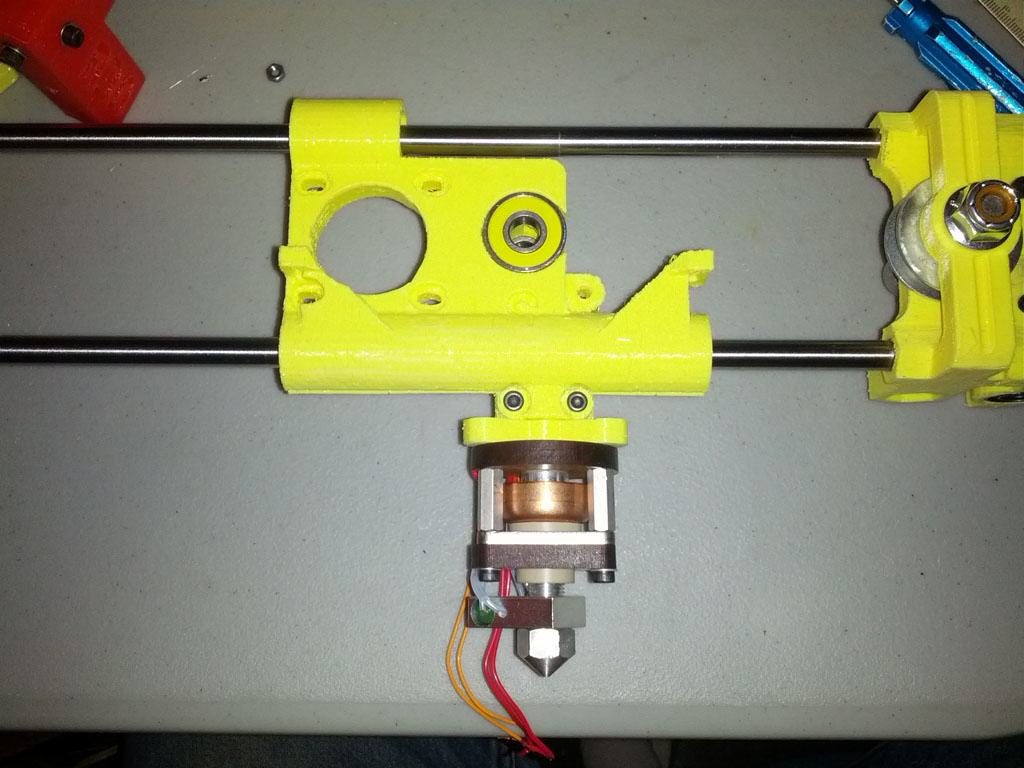
The Z-offset setting of your 3D printer is the distance between the Z home position and the hot end. Calibrating this setting is a key element of attaining the perfect first layer. The Z-offset can also be manipulated to add extra print bed material or to a model on top of another.
The Z-offset of your 3D printer is only one of more than a dozen settings you will need to fiddle with on a filament-based printer. It is also one of the more important ones, especially if you’re trying to make your prints as close to perfect as possible. Check out this primer on what the Z-offset is and how you can use the setting to your advantage.
What is the Z-offset?
Simply put, the Z-offset is the distance between the nozzle and the print bed when the build plate is at the Z home position or when the Z-axis limit is triggered. Setting a Z-offset value protects the build plate from damage, while also ensuring that the first layer of a project is printed correctly.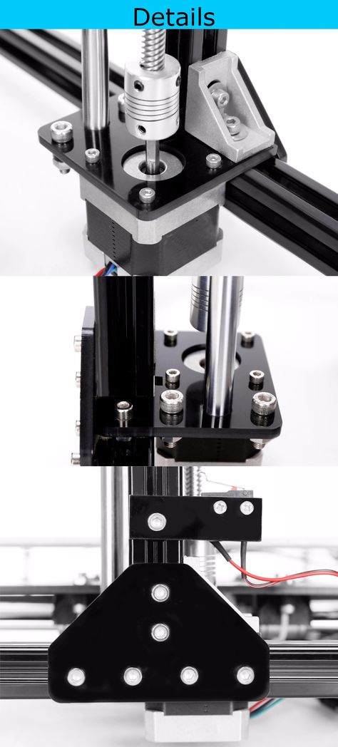
There is an optimal Z-offset setting that will result in a perfect first layer. If the nozzle is too high, the filament might not stick to the bed. If the nozzle is too low, it may result in under-extrusion issues or even cause damage to the print bed. At just the right level, there is just enough pressure on the filament to make it stick to the bed.
The ability to adjust the Z-offset of a 3D printer can also come in handy if you’re adding another material on top of your standard print bed, such as a glass bed or a magnetic PEI plate. It is also possible to start printing on an object atop the print bed or continue a project that had to be paused mid-print.
How to calibrate the Z-offset
Calibrating the Z-offset of your 3D printer is something that you will need to learn eventually. It is absolutely necessary whenever you manipulate the print bed in any way, or even as part of regular maintenance. Depending on the brand and model of your 3D printer, there may be several calibration methods available to you. In this section, we will be running through all these methods.
One requirement that applies to all these methods is that you have to heat the build plate first before calibration. Regardless of the material of your build plate, it will expand upon heating. By calibrating with a hot plate, you will be working with a more accurate simulation of the actual operating conditions of the 3D printer. If you work with different types of filament, just heat the print bed to the highest temperature that you will need.
With that aside, we can start discussing the Z-offset calibration methods.
Manual calibration
Some printers have physical limit switches located along the axes that prevent damage to the print bed by limiting its movement. These are screwed onto the axes and can be moved up and down as necessary. This is an option if you can locate the limit switches on your 3D printer. Do not attempt to do this if you don’t know what you’re doing.
Manual calibration by the movement of the limit switch isn’t the appropriate method if you want to make small and precise adjustments to improve the quality of your first layer.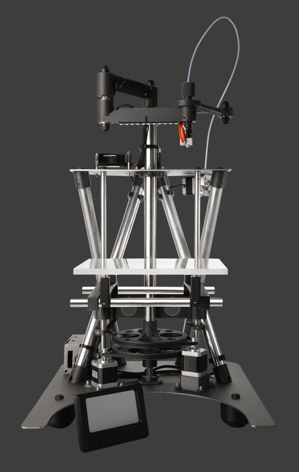 However, it’s a good option to give your print bed more room for later adjustments.
G-Code calibration
If you can edit the G-Code of your 3D printer, you can do this to shift the printer’s entire z-axis. This effectively changes the Z home position of the print bed.
To do this, start by executing the following commands:
- G28 Z0
- G92 Z0.1
In this sequence, the G28 command moves the printhead to the default home position. The G92 command then assigns the value of 0.1 mm. to the printhead’s current position, thereby also shifting the home location downward by a value of 0.1 mm. If you want to shift the home location upward by 0.1 mm, adjust the parameter of the G92 command to the negative value (G92 Z-0.1).
Slicer settings
If you’re using a slicer like Cura, then you can adjust the Z-offset quite easily through the slicer settings. This method currently only applies to the beta of version 5.0. To start, you will need to go to the Marketplace, and download and install the “Z Offset Setting” plugin.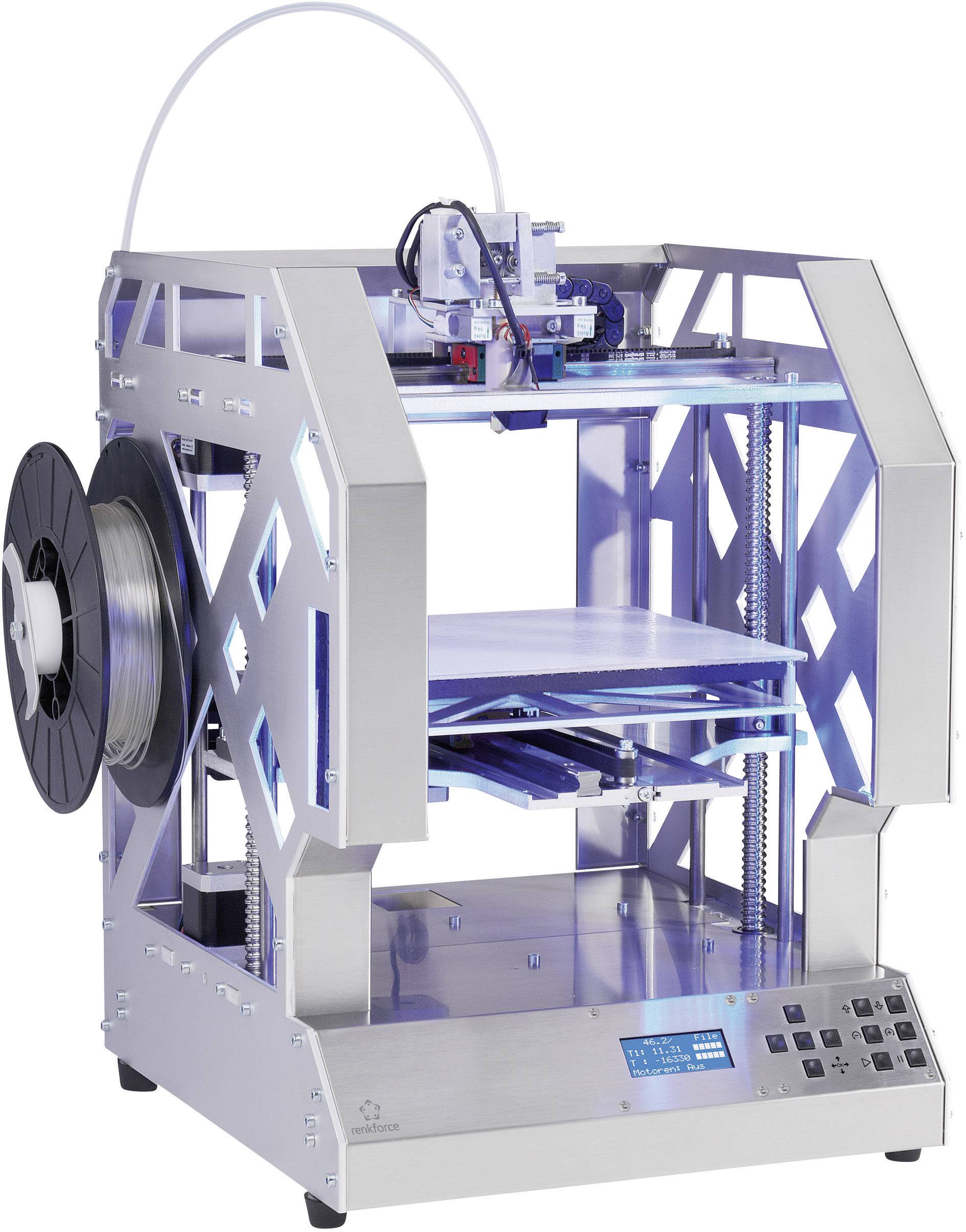
Once installed, just head over to the print settings and the Build Plate Adhesion section. Here, you should already see the “Z Offset” setting with the option to input a value in millimeters. This method makes it a lot easier to experiment with Z-offset settings until you find the setup that works perfectly for your 3D printer.
Calibrating from the printer display
Some of the more advanced 3D printers that run on Marlin firmware even let you change the Z-offset settings directly from the printer’s display panel. The Ender 3 and Ender Pro are just two examples of 3D printers with such features.
The exact location of the Z-offset option may vary depending on which version of Marlin your printer is running, but it should not be hard to find. Adjusting the Z-offset here is even easier than doing it in your slicer, and also lets you experiment with different settings.
Print an endstop
It may seem like a rudimentary solution, but you can place a physical end stop on the Z-axis to adjust the Z-offset. There are several 3D printable models of these end stops. Good examples include this end stop for the Creality Ender 3 and another one for the ANET A8. These replace the standard limit switch that can be found in these printers.
There are slight variations in the various end stops available out there, but they all have similar objectives – adjustment of the Z-offset by simple knob adjustment. This makes it possible to make precise Z-offset adjustments, even just by visual approximation. Those who are more experienced in working with their 3D printers and are very familiar with their performance will likely have fun playing around with this contraption.
No matter which method you go for, getting the Z-offset just right will always involve a healthy amount of trial and error.
Final thoughts
It’s often said that getting the perfect first layer is the key to making a perfect 3D print. A lot of work goes into this first layer – getting the Z-offset value just right is an essential part of that process.
Warning; 3D printers should never be left unattended. They can pose a firesafety hazard.
Printer Calibration and ... | BeyondWiki
In past 3D printing articles, we've looked at different types of 3D printers, FDM printer components, plastic types, why printing problems occur and how to fix them. This article is about how to prepare the printer for the first print or how to start 3D printing after a long period of inactivity.
Until now, 3D printers are quite complex, “incomprehensible machines” that require careful attention and a clear understanding of the device of the printer itself. Unfortunately, at the moment you can't start 3D printing by simply buying a 3D printer, placing it on a surface and pressing the start button - you first need to learn the settings and prepare the machine for printing.
NOTE
Most modern 3D printer manufacturers have their own software to operate the device.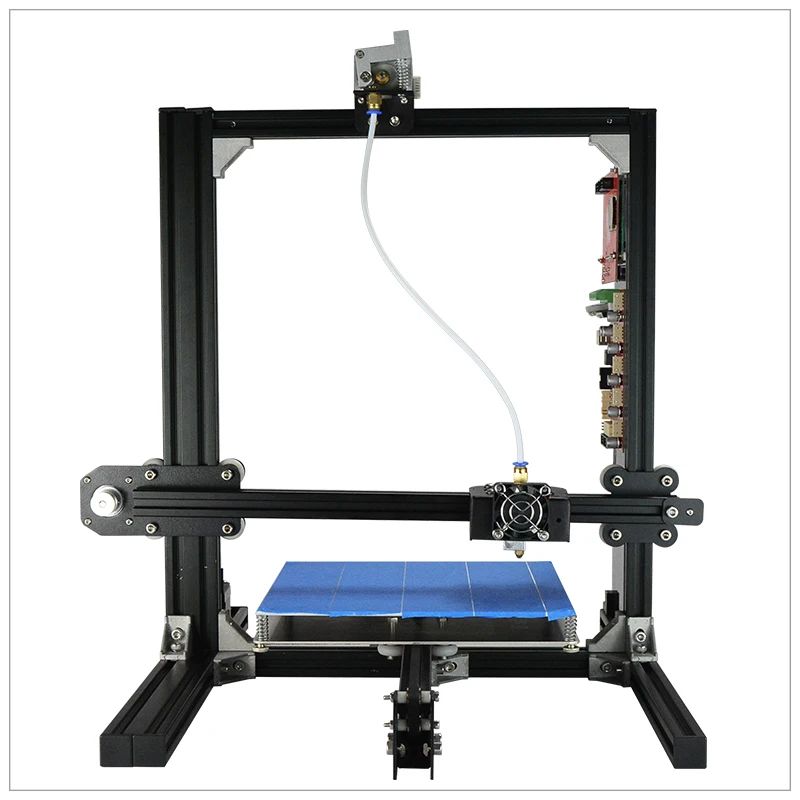 Therefore, each operation described in this manual is performed differently on different printers: somewhere through the firmware, and somewhere manually.
Before you start working with the printer, you need to prepare a space for it: the 3D printer must be installed on a clean, non-flammable surface in a draft-free room; also the plane (for example, a table) where the printer will be installed must be level and stable. Once you have found a suitable location for your 3D printer, you can start setting it up.
Calibration
IMPORTANT
For each printer, calibration can be done in different ways. First you need to check the user manual.
Calibration is an essential part of a 3D printer. First of all, it is necessary to calibrate the Z-axis: usually the Z-axis is regulated from two sides by two stepper motors on steel studs.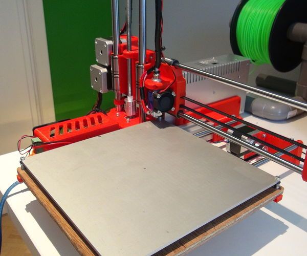 It happens that due to transportation, manual assembly of the printer or careless use, the left side of the axis is higher or lower than the right side. As a result, the X-axis, which is held on the Z-axis, moves, becoming not parallel to the plane of the table.
To solve this problem:
- Calibrate the Z-axis using the printer's built-in calibrator: for example, this function is available on Prusa printers.
- Carry out manual calibration by lifting the Z axis up to the stop.
printer Z-axis raised to the stop Once the Z-axis is calibrated, it is necessary to check the tension of the belts on the X and Y axes. To do this, you need to move the extruder and table to the middle of their axes, and then press the belt with your finger from above and below: When pressed, the belt should show little resistance. It is worth noting that both insufficient and excessive tension can lead to printing problems - in this case, the belts should be tightened. It is also important to check if the leading axles of each axle are sufficiently lubricated.
The last thing to do is to calibrate the extruder - often referred to as “z offset calibration”. To do this, you need to set the calibration parameter so that a sheet of paper passes through the gap between the table and the extruder. At the same time, the sheet should not move too freely or even be sandwiched between the surfaces.
9000 9000 9000
hot", with a heated table to at least 60-80 degrees. The temperature can reach up to 100 degrees if plastics are printed, which require a high heating temperature of the table surface.
Important, if the height of the table on a 3D printer is adjustable at 4 points, then you must first perform this calibration in the middle of the table, changing the “z offset” parameter. Next, the calibration is carried out along the edges, already changing the height of the table, until a sheet of office paper passes into the gap between the table and the extruder in the same way.
Preparing the table and plastic
After all the manipulations with the printer axes, table height and extruder, you can load plastic into the extruder. Before doing this, you need to check that:
- plastic free from dust and dirt
- plastic thread not deformed
- plastic not brittle
- plastic tip cut at an angle
- extruder heated to the melting temperature of plastic
After that, you can load the plastic into the extruder and then wait until the plastic of the corresponding color begins to extrude from the extruder.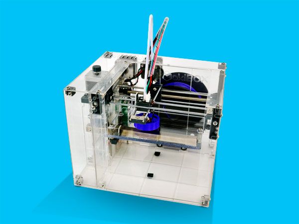
The next step is to prepare the table surface for printing. The guide "Types of Plastics, Their Features and Applications" tells about the different coatings for certain plastics.
There are different algorithms of action for different coatings that improve the adhesion of the material to the surface. In the case of PEI and magnetic coating, it is often enough to wipe the surface with alcohol (Isopropyl alcohol is preferable, but ethyl alcohol is also suitable). If the printer table is covered with glass or a mirror, then it can be treated with adhesive spray or paper glue. It is recommended to cover the table with blue masking tape, which has better adhesive properties than a smooth table. And then, if necessary, treat the print area with an adhesive.
Printer Masking Tape When printing with ABS plastic, you need to apply glue stick for paper on the table, for TPU you need to cover the table with a thin layer of talcum powder, and when printing RUBBER, you must definitely stick transparent tape on the table. Also, after every 3-5 printing sessions, it is required to wipe the surface of the table with alcohol.
Seal
Once the printer has been prepared, the first print can be made. However, it is too early to print the desired models - first you need to print a test cube to evaluate the quality of the print. The model of the cube can be any, but most often it is a cube of 20x20x10 mm or 20x20x20 mm. The printed cube should be even and neat. It is also important to measure the size of the cube with a vernier caliper in order to evaluate the printing error.
If you have problems printing, we recommend that you refer to the Printing Problems and Solutions Guide.
Further, after the successful printing of the calibration cube, do not immediately send the models for printing - it is better to print a few more calibration parts.
Total
A modern 3D printer still requires a reverent attitude and fine tuning.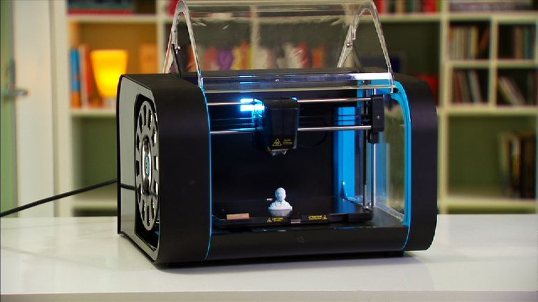 However, over the years, the technology has become more understandable to the user, and today it is much easier to prepare a printer for printing. To do this, it is important to remember that you need to constantly calibrate the printer, adjust its parameters and monitor its operation, since over time the belt tension may loosen, and the axis calibration may go astray after repeated printing.
The Beyond Curriculum Foundation publishes a series of materials within the framework of the Beyond Robotics project with the support of the Chevron public-private partnership and the US Embassy in Kazakhstan.
(There is a solution) How to set the Z offset?
marlin bed leveling g-code anet-a6 print-axis-offset
After watching every possible youtube video on the subject and reading every available source, and although I'm a PhD and quite computer savvy, I still can't get my Anet A6 (no probe) to behave in terms of Z-offset. I switched to silicone table buffers instead of regular springs; now my table is raised by ~5mm and i don't know how to proceed.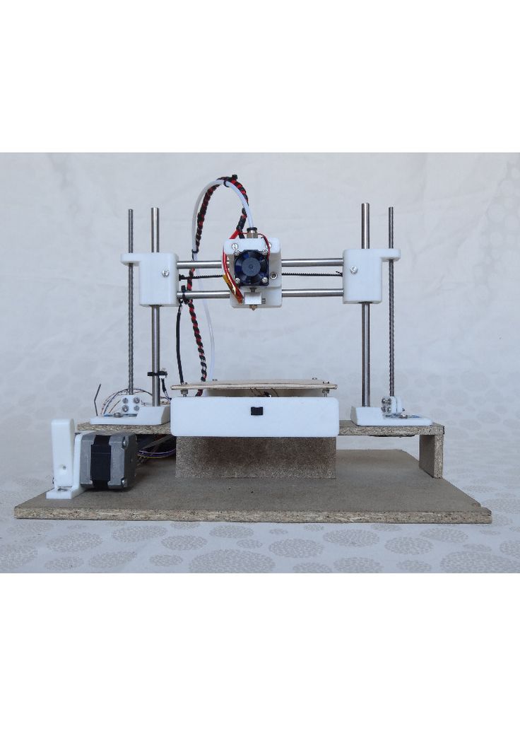 Some observations:
-
G28 causes the nozzle to move towards the center of the table. The display shows X 111 and Y 111. Is it better to place the house in the lower left corner or just in the center?
-
G28 causes the nozzle to slosh over a bed ~5mm deep.
-
I tried approach G92 and approach M428. I don't quite understand what the difference is between them. Can anyone explain why sometimes the former is used and sometimes the latter?
-
I had high hopes for M428 . What could be easier? You physically point the nozzle where it should be, send a command, and that's your new 0,0,0. But probably not. Since my "home" is at 111 111 and apparently the M428 can only be used max 20mm from 0, I get a "too far from reference" error.
-
Anyway, both approaches (also M206 ) did not help. When I am G28 , the nozzle still squishes the table. The display either says Z 5, or Z -5, or whatever I played there, but the nozzle still squelches the poor table.
-
In my LCD menu (Marlin 1.1.9) I don't have Control -> Motion -> Z offset. Since many videos recommend using this, it's pretty sad. Can someone tell me why this option is missing?
-
On a very conceptual level, I don't quite understand why in all the video guides the table screws are completely ignored when discussing Z offset. One guy showed how he fixes a Z offset of 0.3 mm with G-code. But he could easily do it by adjusting the screws... They all say "Z offset means the distance between your nozzle and the table, and here's how to adjust it." Now comes the G-code, or LCD menu, etc. But why does everyone forget that you can adjust the distance between your table and the nozzle with screws?! I can't collect my thoughts at all. In my case, of course, I can't use screws - they've reached their limit, so I need to add extra ones using G-code. But no one seems to really explain it...
Summary: I urgently need a step by step guide for 6 year olds. Let it be 4-year-old children.
@Pixie, 👍1
2 answers
Best answer:
▲ 2
So the new silicone buffers raised the table by 5mm? When this happens, you must also raise the end stop by 5 mm. Otherwise, the printer will lower to the Z-stop, which is actually 5mm below table level. My guess is that buffers can't be compressed by 5mm, so you need to move the end stop to a level where your buffer compression is within reach.
No software offset will work (for your current setup: homing to the table surface does not work as the switch must be activated before any offset can be enabled) other than a hardware change or buffer compression by 5mm. It would be possible to use software offset only when the nozzle is off the table surface (near the table). The only thing you would have to do is to add to your starting G-code:
G0 Z5 ; Move head 5mm G92 Z0 ; Let's call it Z = 0
If #define Z_SAFE_HOOMING is enabled, you must comment out the line in the config file to make it home Z at homed X, Y position. codes and firmware Marlin G-codes, they will not be able to help you unless you fix the homing on the table surface. Currently you need to do a hardware fix, your end stop is below the level of the table surface. An alternative is to remove the self-aligned Z above the table surface and redefine the Z offset. Hardware fix is the best solution, and if you can manage to print the fancy Z endstop holder and its counterpart with a screw, you should be able to level the table more easily.
For example, M428 can set an offset, yes, but it needs a reference; this link is a homing link or current position. The current position of the printer that has just been turned on is meaningless, it could be anywhere in the print volume. So you need to call the endpoints first, which is not possible when they are not available (no table compression).
, @ 0scar
▲ 0
Setting any offset will move the entire print ("effectively shifts the coordinate space") - so you can adjust the print above or below the table, or shift a few centimeters to the right, for example - and then your print may not actually fit the print space. For example: my frame is blocking X moves at the top, I can set the offset to 20mm X to avoid letterpress accident (so move the print). Or when setting a new seal on top of another seal, thus shifting the position, etc. If you call
 M428 at any position, the current position will become the new offset. The current offset settings are reported to M503 (or M206 without parameters).
Also G92 is used as a special operation when using relative positioning. It makes sense for moving the extruder, but is not used in practice for moving the print head. I would argue that any such calls to X,Y,Z sound like some kind of hack, and you need to know exactly what you are doing in order to fool the printer logic in this way. I would avoid it altogether.
Typically (0,0,0) for Cartesian printers is the nearest bottom left point of the table. If properly zeroing the printer is what you're trying to achieve, then you should:
- zero any X,Y,Z offsets:
M206 X0 Y0 Z0(unless some of them are justified, as in the frame example) - save this setting for the future:
M500 - home printer - it zeros out the position and then automatically retreats to some "safe distance" (programmed in the firmware).
Learn more


