3D printed transmission
Mechanical Engineer 3D Prints a Working 5-Speed Transmission for a Toyota 22RE Engine - 3DPrint.com
Who says that you can’t make anything useful on a desktop 3D printer? Sure, there are plenty of designs that you can find on 3D printing repository websites which make you question the motive of the designers — but at the same time, there are engineers and designers creating things that make you just stop and say, “WOW!”
One of these latter instances comes in the form of a 3D printed 5-speed transmission for a Toyota 22RE engine, created by a mechanical engineer named Eric Harrell of Santa Cruz, California. Not only does it look legitimate, but it also is completely functional.
You may recall a story that we did back in January about a 3D printed Toyota Engine. It was also designed by Harrell, after he completely reverse engineered a real Toyota 22RE engine. It received such a great reception from both Thingiverse users and the national media, that Harrell decided to take his creation one step further, providing this latest 3D printed transmission to complement the engine.
The two actually can be combined to create the ultimate piece of 3D printed machinery.
“I made the transmission due to the the success of my first upload, the 4 cylinder Toyota engine,” Harrell tells 3DPrint.com. “The overall number of people that were interested was overwhelming. I never thought that many people would be interested in it, yet actually print and build it, due to the shear complexity and print time involved. So far 8 people have made the engine and many more are in the process.”
In all, it will take about 48 hours of print time to print out all of the individual pieces needed to assemble the transmission. Once the pieces have all been printed, they will need to be assembled using the diagrams that Harrell provides. He admits that it’s not an easy task to put the transmission together once the parts have been printed, but welcomes questions from anyone who has difficulty doing so.
Transmission and engine mated together.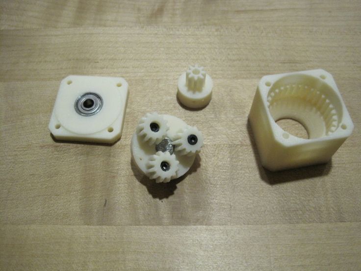
“If one was to build either my transmission or engine, they would have a pretty good idea of how to put an actual engine together since these are modeled after real parts,” Harrell tells us. “Which is great, because most people that are interested in 3D printing would never get the opportunity to actually rebuild an engine or transmission.”
While the majority of the transmission is 3D printed, there are some smaller parts which can not be printed on a desktop 3D printer, such as the 3mm rod, (18) 623zz bearings, (20) 3mm washers, and a few other small odds and ends like screws and bolts. At the same time, Harrell doesn’t ensure that all the parts will be ready to go off of the printer. Depending on the 3D printer used, some of them may need to be scaled up or down in order to fit together properly. Rather than scaling the parts, he also suggests that you could simply file them down where needed.
“The transmission works exactly like most manual transmissions found in any car or truck,” explained Harrell.
“However, I can barely explain how it works. It’s fairly hard to grasp unless you assemble one or see an animation of one opened up.”
Regardless of the time required for printing and assembly, this has to be one of the most incredible designs that we have come across yet on Thingiverse. Most incredibly, Harrell tells us that it could absolutely be used in a real vehicle, since it is a scaled down version of the real thing.
What do you think about this incredible 3D printed Toyota transmission? Have you, or will you be 3D printing your own? Discuss in the 3D Printed Toyota Transmission forum thread on 3DPB.com. Check out the video below of the 3D printed transmission in action.
Stay up-to-date on all the latest news from the 3D printing industry and receive information and offers from third party vendors.
Tagged with: 22re transmission • 3d printed engine • 3d printed toyota transmission • 3d printed transmission • 5-speed transmission • thingiverse • toyota 22re engine • toyota transmission • transmission
Please enable JavaScript to view the comments powered by Disqus.
3ders.org - Engineer builds 3D printed working 5 speed transmission for Toyota 22RE engine
Mar. 13, 2015 | By Alec
While we see plenty of very impressive 3D printed objects complete with plenty of moving designs, few building projects were more inspiring than Eric Harrell’s PLA working replica of the Toyota 4 Cylinder Engine 22RE. To refresh your memory, Eric’s recreation is a reverse-engineered engine that has been scaled down to 35% of the original size, as this was simply the largest possible option for his own RepRap Prusa 3D printer. Assembled with magnets, the 80 different components probably took up about a whole 1KG roll of PLA filament and took more than 34 hours to completely print. ‘It's definitely is a challenge for you and your printer,’ he wrote at the time and he’s right.
But that was last January, and now Eric’s already back for more. Going for a larger and more complex model, he has now 3D printed the four-wheel-drive gear box for his previous model: the 5 speed transmission Toyota 22RE.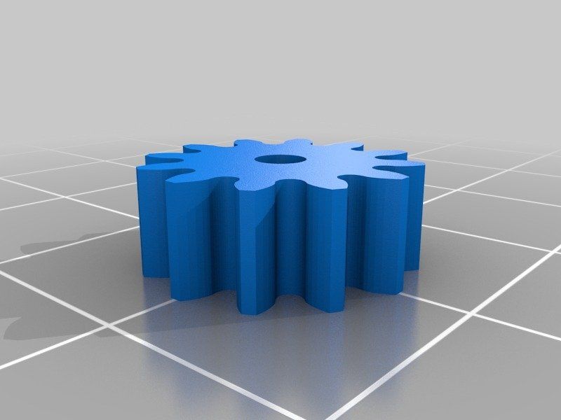 It’s a fully working miniature replica of that matches his previous project, complete with a reverse gear. Like the engine, it’s not for the beginners. ‘This model is more complex than the engine,’ he writes, though it is in fact far more complex to assemble.
Eric has even declined to produce a tutorial as there are simply too many steps and parts to easily convey in assembly diagrams. If you want to try it, download all the files from Thingiverse and follow this basic guide: ‘You will have to figure out which holes to drill, ream, and tap. There's not too many of them. Any questions, just ask. See excel spread sheet for parts list, descriptions, and notes about parts. Most parts will require a Brim to prevent curling.’ You will also have to add a few bearings, screws and a rod which you can order from amazon.
The transmission linked up to Eric's earlier engine.
It is, in short, a very complex and challenging project, but the first step towards a 3D printed car.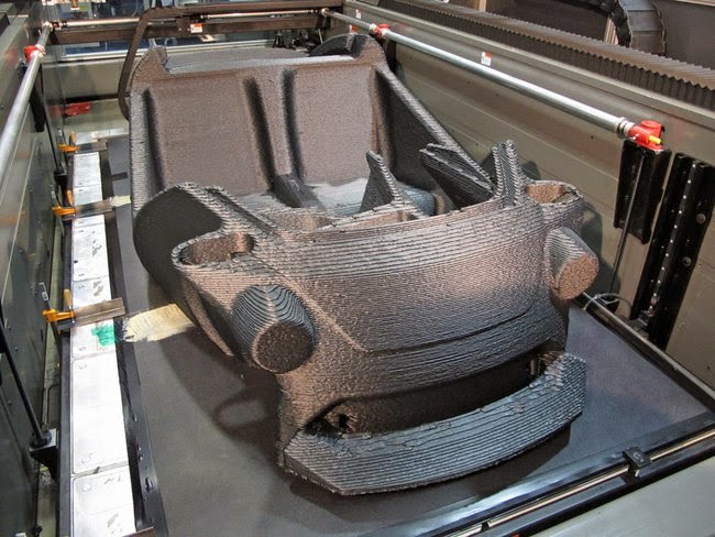 For this transmission box can actually be lined up to mate with the engine, though you might have to modify the engine stand to get it to come together. As Eric explained to 3ders.org, he designed this replica as a follow-up on an earlier iteration. ‘I made the transmission due to the the success of my first upload, the 4 cylinder Toyota engine. The overall number of people that were interested was overwhelming. I never thought that many people would be interested in it yet actually print and build it, due to the sheer complexity and print time involved,’ he revealed. ‘But so far 8 people have made the engine and many more are in the process.’
Just like for that earlier project, Eric (who has a degree in Mechanical Engineering) decided to 3D print replicas of engine parts because he has been working with the real thing for quite a while. ‘I thought that there wasn't anything like a scale model of an engine that showed how all the components worked. The scaled engine and the transmission show how these components work and allow someone to hold it and actually rotate the parts,’ he explains, and it’s clear how these have educational value. What trade school wouldn’t want their students to work with a plastic version before starting on the real thing?
Eric believes that building a 3D printed version will give beginning mechanics everywhere a good idea of how these parts work. ‘If one was to build either my transmission or engine, they would have a pretty good idea of how to put an actual engine together since these are modeled after real parts. Which is great, because most people that are interested in 3D printing would never get the opportunity to actually rebuild an engine or transmission,’ he says. Of course, as its plastic it can never be a truly working transmission, but its moving on the exact same concepts. ‘If it was somehow scaled back up to full size, and made out of a more durable material than PLA it should be a fully working transmission,’ he argues.
And as was the case for the engine, Eric designed this entire thing in SolidWorks software. ‘All dimensions were roughly taken with calipers and all the parts were redesigned with FDM printing in mind,’ he says. These files were subsequently 3D printed with his own RepRap Prusa 3D printer, as well as with a Kossel mini. All of it was made in PLA, taking about 48 hours to 3D print. Really the only added parts are the fasteners, bearings, and a 3mm rod.
After two of these impressive projects, the logical question of ‘What’s next?’ arises. After all, Eric is almost halfway towards 3D printing a whole car. But rest assured, as it could be coming: ‘The next part to make would be the transfer case and possibly the differential after that,’ he reveals. We can’t wait.
Check out the transmission in action here.
Posted in 3D Printing Applications
Maybe you also like:
- Onshape raises $65 million for CAD software, public beta goes live
- Robosavvy debuts 3D printed Segway-riding robot in Barcelona
- Ultra-realistic 3D printed organs let Japanese doctors practice real surgery now
- 3D printed mouthpiece Hydra-Guard helps athletes stay hydrated during games
- CeramicSpeed debuts $1000 3D printed hollow titanium pulley wheels for high quality cycling
- Boeing files patent for 3D printing of aircraft parts, printed 20,000 parts for its planes
- Test your 3D printer's limits with this hard-to-print test object
- Create a 3D printed robot that dances like Michael Jackson with new robot kit
- Create your own 3D printed icicle projects using the Icicle Atlas
All about 3D printing.
 additive manufacturing. Basic concepts.
 - 1 Technology
- 2 Terminology
- 3 Fundamentals
- 4 Printing Technologies
- 5 3D printers
- 6 Application
- 7 Domestic and hobby use
- 8 Clothing
- 9 3D bioprinting
- 10 3D printing of implants and medical devices
- 11 3D printing services
- 12 Research into new applications
- 13 Intellectual Property
- 14 Influence of 3D printing
- 15 Space research
- 16 Social change
- 17 Firearms
Technology
Charles Hull - the father of modern 3D printing
3D printing is based on the concept of building an object in successive layers that display the contours of the model.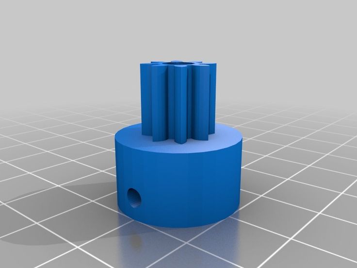 In fact, 3D printing is the complete opposite of traditional mechanical production and processing methods such as milling or cutting, where the appearance of the product is formed by removing excess material (so-called "subtractive manufacturing").
3D printers are computer-controlled machines that build parts in an additive way. Although 3D printing technology appeared in the 80s of the last century, 3D printers were widely used commercially only in the early 2010s. The first viable 3D printer was created by Charles Hull, one of the founders of 3D Systems Corporation. At the beginning of the 21st century, there was a significant increase in sales, which led to a sharp drop in the cost of devices. According to the consulting firm Wohlers Associates, the global market for 3D printers and related services reached $2.2 billion in 2012, growing by 29%.% compared to 2011.
3D printing technologies are used for prototyping and distributed manufacturing in architecture, construction, industrial design, automotive, aerospace, military-industrial, engineering and medical industries, bioengineering (to create artificial fabrics), fashion and footwear, jewelry, in education, geographic information systems, food industry and many other areas.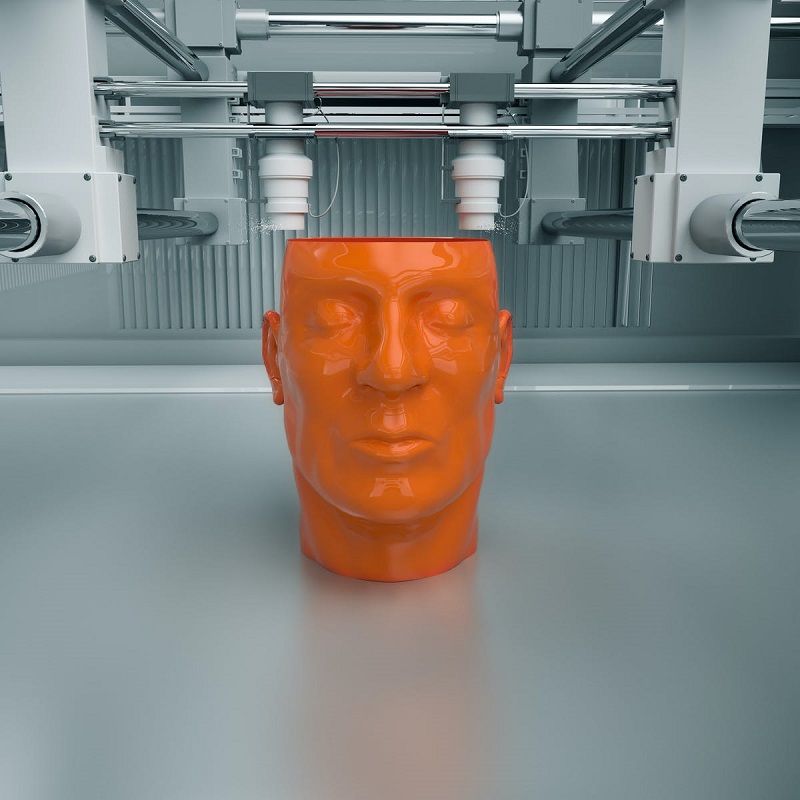 According to research, open source home 3D printers will allow you to win back the capital costs of your own purchase through the economy of household production of items.
Terminology
Additive manufacturing involves the construction of objects by adding the necessary material, and not by removing excess, as is the case with subtractive methods
The term "additive manufacturing" refers to the technology of creating objects by applying successive layers material. Models made using the additive method can be used at any stage of production - both for the production of prototypes (so-called rapid prototyping) and as finished products themselves (so-called rapid production).
In manufacturing, especially machining, the term "subtractive" implies more traditional methods and is a retronym coined in recent years to distinguish between traditional methods and new additive methods.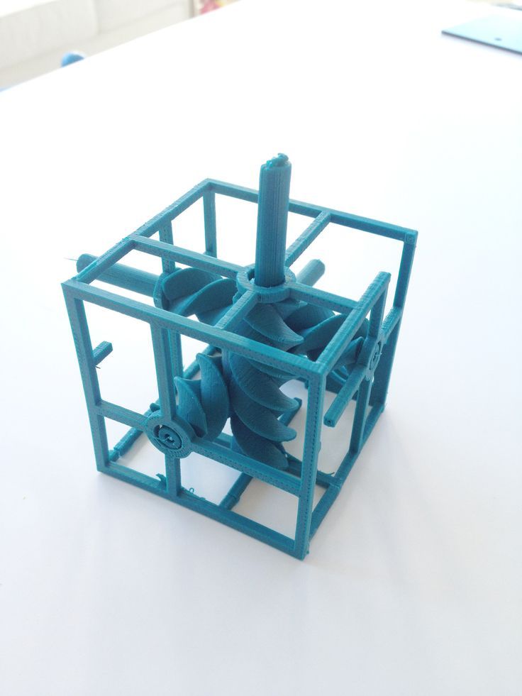 Although traditional manufacturing has used essentially "additive" methods for centuries (such as riveting, welding, and screwing), they lack a 3D information technology component. Machining, on the other hand, (the production of parts of an exact shape), as a rule, is based on subtractive methods - filing, milling, drilling and grinding.
The term "stereolithography" was defined by Charles Hull in a 1984 patent as "a system for generating three-dimensional objects by layering".
Fundamentals
3D printed models
3D models are created by hand-held computer graphic design or 3D scanning. Hand modeling, or the preparation of geometric data for the creation of 3D computer graphics, is somewhat like sculpture. 3D scanning is the automatic collection and analysis of data from a real object, namely shape, color and other characteristics, with subsequent conversion into a digital three-dimensional model.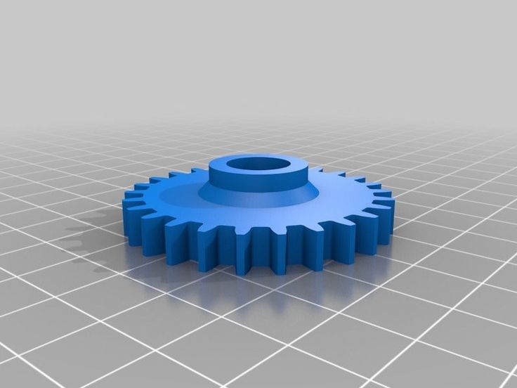
Both manual and automatic creation of 3D printed models can be difficult for the average user. In this regard, 3D printed marketplaces have become widespread in recent years. Some of the more popular examples include Shapeways, Thingiverse, and Threeding.
3D printing
The following digital models are used as drawings for 3D printed objects , powder, paper or sheet material, building a 3D model from a series of cross sections. These layers, corresponding to virtual cross-sections in the CAD model, are connected or fused together to create an object of a given shape. The main advantage of this method is the ability to create geometric shapes of almost unlimited complexity.
"Resolution" of the printer means the thickness of the applied layers (Z-axis) and the accuracy of positioning the print head in the horizontal plane (along the X and Y axes). Resolution is measured in DPI (dots per inch) or micrometers (the obsolete term is "micron").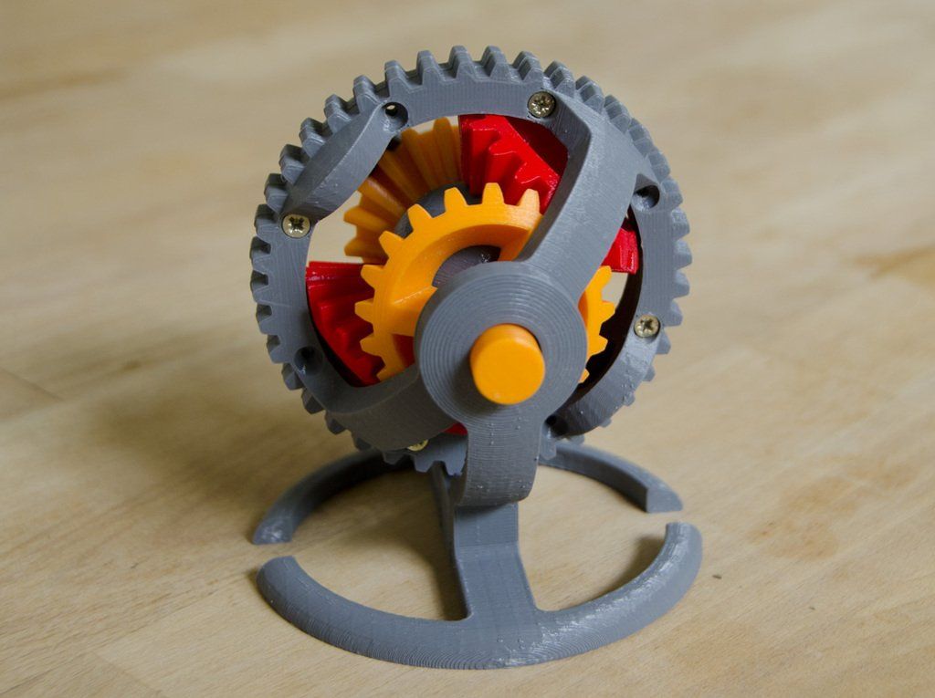 Typical layer thicknesses are 100µm (250 DPI), although some devices like the Objet Connex and 3D Systems ProJet are capable of printing layers as thin as 16µm (1600 DPI). The resolution on the X and Y axes is similar to that of conventional 2D laser printers. A typical particle size is about 50-100µm (510 to 250 DPI) in diameter.
One of the methods for obtaining a digital model is 3D scanning. Pictured here is a MakerBot Digitizer
3D Scanner Building a model using modern technology takes hours to days, depending on the method used and the size and complexity of the model. Industrial additive systems can typically reduce the time to a few hours, but it all depends on the type of plant, as well as the size and number of models produced at the same time.
Traditional manufacturing methods such as injection molding can be less expensive when producing large batches of polymer products, but additive manufacturing has advantages in small batch production, allowing for higher production rates and design flexibility, along with increased cost per unit produced.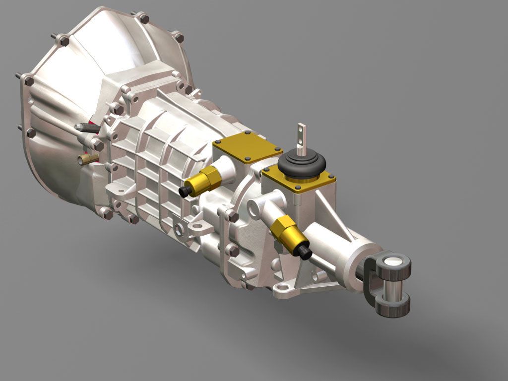 In addition, desktop 3D printers allow designers and developers to create concept models and prototypes without leaving the office.
Machining
FDM Type 3D Printers
Although the resolution of the printers is adequate for most projects, printing slightly oversized objects and then subtractively machining them with high-precision tools allows you to create models of increased accuracy.
The LUMEX Avance-25 is an example of devices with a similar combined manufacturing and processing method. Some additive manufacturing methods allow for the use of multiple materials, as well as different colors, within a single production run. Many of the 3D printers use "supports" or "supports" during printing. Supports are needed to build model fragments that are not in contact with the underlying layers or the working platform. The supports themselves are not part of the given model, and upon completion of printing, they either break off (in the case of using the same material as for printing the model itself), or dissolve (usually in water or acetone - depending on the material used to create the supports). ).
).
Printing technologies
Since the late 1970s, several 3D printing methods have come into being. The first printers were large, expensive and very limited.
Complete skull with supports not yet removed
A wide variety of additive manufacturing methods are now available. The main differences are in the layering method and consumables used. Some methods rely on melting or softening materials to create layers: these include selective laser sintering (SLS), selective laser melting (SLM), direct metal laser sintering (DMLS), fusing deposition printing (FDM or FFF). Another trend has been the production of solid models by polymerization of liquid materials, known as stereolithography (SLA).
In the case of lamination of sheet materials (LOM), thin layers of material are cut to the required contour, and then joined into a single whole. Paper, polymers and metals can be used as LOM materials.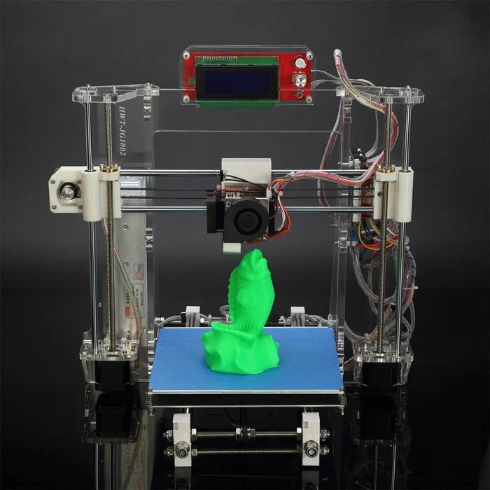 Each of these methods has its own advantages and disadvantages, which is why some companies offer a choice of consumables for building a model - polymer or powder. LOM printers often use regular office paper to build durable prototypes. The key points when choosing the right device are the speed of printing, the price of a 3D printer, the cost of printed prototypes, as well as the cost and range of compatible consumables.
Printers that produce full-fledged metal models are quite expensive, but it is possible to use less expensive devices for the production of molds and subsequent casting of metal parts.
The main methods of additive manufacturing are presented in the table:
| | ||
| Method | Technology | Materials used |
| Extrusion | Fused deposition modeling (FDM or FFF) | Thermoplastics (such as polylactide (PLA), acrylonitrile butadiene styrene (ABS), etc.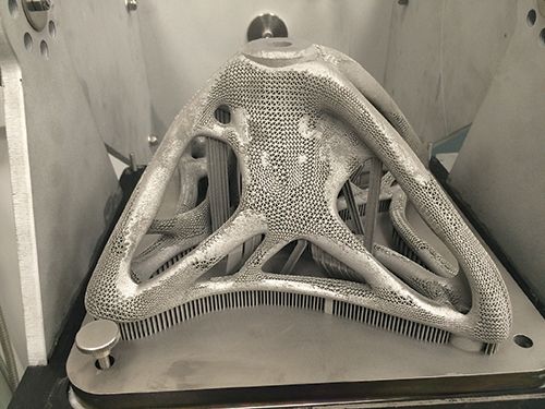 ) ) |
| Wire | Manufacture of arbitrary shapes by electron beam fusing (EBFȝ) | Virtually all metal alloys |
| Powder | Direct Metal Laser Sintering (DMLS) | Virtually all metal alloys |
| Electron Beam Melting (EBM) | Titanium alloys | |
| Selective laser melting (SLM) | Titanium alloys, cobalt-chromium alloys, stainless steel, aluminum | |
| Selective heat sintering (SHS) | Powder thermoplastics | |
| Selective laser sintering (SLS) | Thermoplastics, metal powders, ceramic powders | |
| Inkjet | 3D Inkjet Printing (3DP) | Gypsum, plastics, metal powders, sand mixtures |
| Lamination | Lamination Object Manufacturing (LOM) | Paper, metal foil, plastic film |
| Polymerization | Stereolithography (SLA) | Photopolymers |
| Digital LED Projection (DLP) | Photopolymers |
Extrusion Printing
Fused Deposition Modeling (FDM/FFF) was developed by S. Scott Trump in the late 1980s and commercialized in the 1990s by Stratasys, a company of which Trump is credited as one of the founders. Due to the expiration of the patent, there is a large community of open source 3D printer developers as well as commercial organizations using the technology. As a consequence, the cost of devices has decreased by two orders of magnitude since the invention of the technology.
3D printers range from simple do-it-yourself printers to plastic...
Fusion printing process involves the creation of layers by extrusion of a fast-curing material in the form of microdrops or thin jets. Typically, consumable material (such as thermoplastic) comes in the form of spools from which the material is fed into a printhead called an "extruder". The extruder heats the material to its melting temperature, followed by extrusion of the molten mass through a nozzle. The extruder itself is driven by stepper motors or servomotors to position the printhead in three planes. The movement of the extruder is controlled by a manufacturing software (CAM) linked to a microcontroller.
A variety of polymers are used as consumables, including acrylonitrile butadiene styrene (ABS), polycarbonate (PC), polylactide (PLA), high pressure polyethylene (HDPE), polycarbonate-ABS blends, polyphenylene sulfone (PPSU), etc. Typically, polymer supplied in the form of a filler made of pure plastic. There are several projects in the 3D printing enthusiast community that aim to recycle used plastic into materials for 3D printing. The projects are based on the production of consumables using shredders and melters.
FDM/FFF technology has certain limitations on the complexity of the generated geometric shapes. For example, the creation of suspended structures (such as stalactites) is impossible by itself, due to the lack of necessary support. This limitation is compensated by the creation of temporary support structures that are removed after printing is completed.
Powder print
Selective sintering of powder materials is one of the additive manufacturing methods. Model layers are drawn (sintered) in a thin layer of powdered material, after which the work platform is lowered and a new layer of powder is applied. The process is repeated until a complete model is obtained. The unused material remains in the working chamber and serves to support the overhanging layers without requiring the creation of special supports.
The most common methods are based on laser sintering: selective laser sintering (SLS) for working with metals and polymers (e.g. polyamide (PA), glass fiber reinforced polyamide (PA-GF), glass fiber (GF), polyetheretherketone) (PEEK), polystyrene (PS), alumide, carbon fiber reinforced polyamide (Carbonmide), elastomers) and direct metal laser sintering (DMLS).
... to expensive industrial plants working with metals
Selective Laser Sintering (SLS) was developed and patented by Carl Deckard and Joseph Beeman of the University of Texas at Austin in the mid-1080s under the auspices of the Defense Advanced Research Projects Agency (DARPA).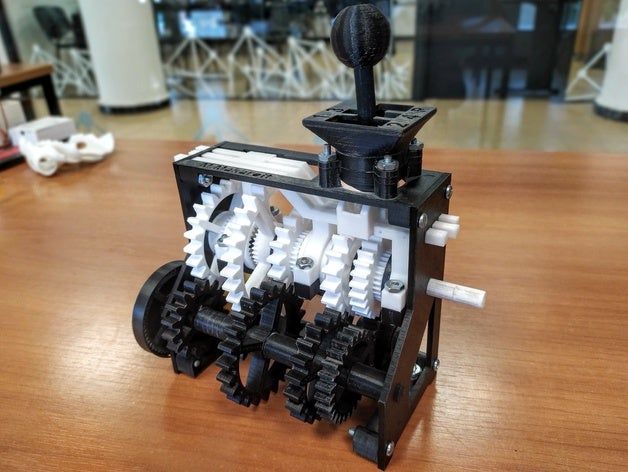 A similar method was patented by R. F. Householder in 1979, but has not been commercialized.
Selective laser melting (SLM) is characterized by the fact that it does not sinter, but actually melts the powder at the points of contact with a powerful laser beam, allowing you to create high-density materials that are similar in terms of mechanical characteristics to products made by traditional methods.
Electron Beam Melting (EBM) is a similar method for the additive manufacturing of metal parts (eg titanium alloys) but using electron beams instead of lasers. EBM is based on melting metal powders layer by layer in a vacuum chamber. In contrast to sintering at temperatures below melting thresholds, models made by electron beam melting are characterized by solidity with a corresponding high strength.
Finally, there is the 3D inkjet printing method. In this case, a binder is applied to thin layers of powder (gypsum or plastic) in accordance with the contours of successive layers of the digital model. The process is repeated until the finished model is obtained. The technology provides a wide range of applications, including the creation of color models, suspended structures, the use of elastomers. The design of models can be strengthened by subsequent impregnation with wax or polymers.
Lamination
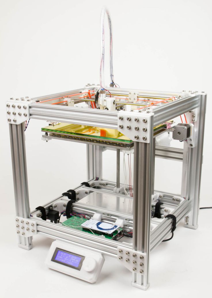
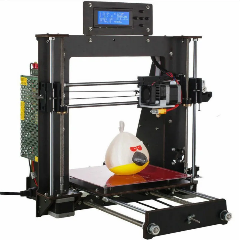
FDM 3D printers are the most popular among hobbyists and enthusiasts
Some printers use paper as a material for building models, thereby reducing the cost of printing. Such devices experienced the peak of popularity in the 1990s. The technology consists in cutting out the layers of the model from paper using a carbon dioxide laser with simultaneous lamination of the contours to form the finished product.
In 2005, Mcor Technologies Ltd developed a variant of the technology that uses plain office paper, a tungsten carbide blade instead of a laser, and selective adhesive application.
There are also device variants that laminate thin metal and plastic sheets.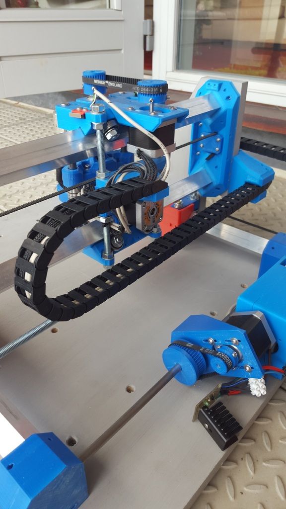
Photopolymerization
3D printing allows you to create functional monolithic parts of complex geometric shapes, like this jet nozzle
Stereolithography technology was patented by Charles Hull in 1986. Photopolymerization is primarily used in stereolithography (SLA) to create solid objects from liquid materials. This method differs significantly from previous attempts, from the sculptural portraits of François Willem (1830-1905) to photopolymerization by the Matsubara method (1974).
The Digital Projection Method (DLP) uses liquid photopolymer resins that are cured by exposure to ultraviolet light emitted from digital projectors in a coated working chamber. After the material has hardened, the working platform is immersed to a depth equal to the thickness of one layer, and the liquid polymer is irradiated again. The procedure is repeated until the completion of the model building. An example of a rapid prototyping system using digital LED projectors is the EnvisionTEC Perfactory.
Inkjet printers (eg Objet PolyJet) spray thin layers (16-30µm) of photopolymer onto the build platform until a complete model is obtained. Each layer is irradiated with an ultraviolet beam until hardened. The result is a model ready for immediate use. The gel-like support material used to support the components of geometrically complex models is removed after the model has been handcrafted and washed. The technology allows the use of elastomers.
Ultra-precise detailing of models can be achieved using multiphoton polymerization. This method is reduced to drawing the contours of a three-dimensional object with a focused laser beam. Due to non-linear photoexcitation, the material solidifies only at the focusing points of the laser beam. This method makes it easy to achieve resolutions above 100 µm, as well as build complex structures with moving and interacting parts.
Another popular method is curing with LED projectors or "projection stereolithography".
Projection stereolithography
This method involves dividing a 3D digital model into horizontal layers, converting each layer into a 2D projection similar to photomasks. The 2D images are projected onto successive layers of photopolymer resin that harden according to the projected contours.
In some systems, the projectors are located at the bottom, helping to level the surface of the photopolymer material when the model moves vertically (in this case, the build platform with the applied layers moves up, rather than sinking into the material) and reduces the production cycle to minutes instead of hours.
The technology allows you to create models with layers of several materials with different curing rates.
Some commercial models, such as the Objet Connex, apply resin using small nozzles.
3D printers
Industrial plants
Industrial adoption of additive manufacturing is proceeding at a rapid pace. For example, US-Israeli joint venture Stratasys supplies $2,000 to $500,000 additive manufacturing machines, while General Electric uses high-end machines to produce gas turbine parts.
Home appliances
LOM takes papier-mâché to the next level The development of 3D printers for home use is being pursued by a growing number of companies and enthusiasts. Most of the work is done by amateurs for their own and public needs, with help from the academic community and hackers.
The oldest and longest running project in the desktop 3D printer category is RepRap. The RepRap project aims to create free and open source (FOSH) 3D printers provided under the GNU General Public License. RepRap devices are capable of printing custom-designed plastic components that can be used to build clones of the original device. Individual RepRap devices have been successfully applied to the production of printed circuit boards and metal parts.
Due to the open access to drawings of RepRap printers, many of the projects adopt the technical solutions of analogues, thus creating a semblance of an ecosystem consisting mostly of freely modifiable devices. The wide availability of open source designs only encourages variations. On the other hand, there is a significant variation in the level of quality and complexity of both the designs themselves and the devices manufactured on their basis. The rapid development of open source 3D printers is leading to a rise in popularity and the emergence of public and commercial portals (such as Thingiverse or Cubify) offering a variety of printable 3D designs. In addition, the development of technology contributes to the sustainable development of local economies through the possibility of using locally available materials for the production of printers.
Stereolithographic 3D printers are often used in dental prosthetics
The cost of 3D printers has been declining at a significant rate since about 2010: devices that cost $20,000 at the time are now $1,000 or less. Many companies and individual developers are already offering budget RepRap kits under $500. The Fab@Home open source project has led to the development of general purpose printers capable of printing anything that can be squeezed through a nozzle, from chocolate to silicone putty and chemicals.
Printers based on this design have been available as kits since 2012 for around $2,000. Some 3D printers, including the mUVe 3D and Lumifold, are designed to be as affordable as possible from the start, with the Peachy Printer being priced around $100. .
Professional Kickstarter funded printers often perform well: Rapide 3D printers are quiet and fumes free at $1499. 3D Doodler's '3D Printing Pen' Raised $2.3M in Kickstarter donations, with a selling price of $99 for the device itself. True, it is difficult to call the 3D Doodler a full-fledged 3D printer.
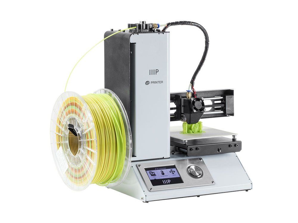
3D Systems Cube is a popular consumer 3D printer
As prices drop, 3D printers are becoming more attractive for home production. In addition, home use of 3D printing technologies can reduce the environmental footprint of industry by reducing the volume of consumables and the energy and fuel costs of transporting materials and goods.
Parallel to the creation of home 3D-printing devices, the development of devices for processing household waste into printed materials, the so-called. Recyclebot. For example, the commercial model Filastrucer was designed to recycle plastic waste (shampoo bottles, milk containers) into inexpensive consumables for RepRap printers. Such methods of household disposal are not only practical, but also have a positive impact on the ecological situation.
The development and customization of RepRap 3D printers has created a new category of semi-professional printers for small businesses. Manufacturers such as Solidoodle, RoBo and RepRapPro offer kits for under $1,000. The accuracy of these devices is between industrial and consumer printers. Recently, high-performance printers using a delta-shaped coordinate system, or the so-called "delta robots", are gaining popularity. Some companies offer software to support printers made by other companies.
Application
The use of LED projectors helps reduce the cost of stereolithography printers. In the illustration DLP printer Nova
3D printing allows you to equalize the cost of producing one part and mass production, which poses a threat to large-scale economies.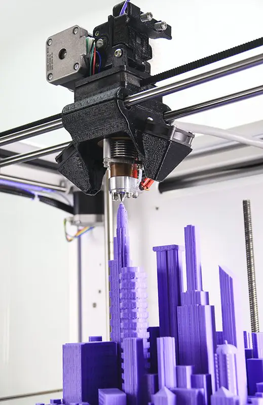 The impact of 3D printing may be similar to the introduction of manufacture. In the 1450s, no one could predict the consequences of the printing press, in the 1750s, no one took the steam engine seriously, and transistors 19The 50s seemed like a curious innovation. But the technology continues to evolve and is likely to have an impact on every scientific and industrial branch with which it comes into contact.
The earliest application of additive manufacturing can be considered rapid prototyping, aimed at reducing the development time of new parts and devices compared to earlier subtractive methods (too slow and expensive). The improvement of additive manufacturing technologies leads to their spread in various fields of science and industry. The production of parts previously only available through machining is now possible through additive methods, and at a better price.
Applications include breadboarding, prototyping, molding, architecture, education, mapping, healthcare, retail, etc.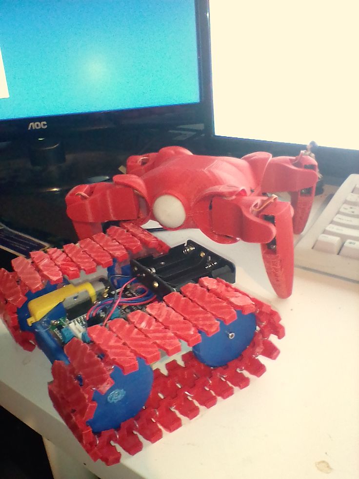
Industrial applications:
Rapid prototyping: Industrial 3D printers have been used for rapid prototyping and research since the early 1980s . As a rule, these are quite large installations using powder metals, sand mixtures, plastics and paper. Such devices are often used by universities and commercial companies.
Advances in rapid prototyping have led to the creation of materials suitable for the production of final products, which in turn has contributed to the development of 3D production of finished products as an alternative to traditional methods. One of the advantages of fast production is the relatively low cost of manufacturing small batches.
Rapid production: Rapid production remains a fairly new method whose possibilities have not yet been fully explored. Nevertheless, many experts tend to consider rapid production a new level of technology. Some of the most promising areas for rapid prototyping to adapt to rapid manufacturing are selective laser sintering (SLS) and direct metal sintering (DMLS).
Bulk customization: Some companies offer services for customizing objects using simplified software and then creating unique custom 3D models. One of the most popular areas was the manufacture of cell phone cases. In particular, Nokia has made publicly available the designs of its phone cases for user customization and 3D printing.
Mass production: The current low print speed of 3D printers limits their use in mass production. To combat this shortcoming, some FDM devices are equipped with multiple extruders, allowing you to print different colors, different polymers, and even create several models at the same time. In general, this approach increases productivity without requiring the use of multiple printers - a single microcontroller is enough to operate multiple printheads.
Devices with multiple extruders allow the creation of several identical objects from only one digital model, but at the same time allow the use of different materials and colors. The print speed increases in proportion to the number of print heads. In addition, certain energy savings are achieved through the use of a common working chamber, which often requires heating. Together, these two points reduce the cost of the process.
Many printers are equipped with dual printheads, however this configuration is only used for printing single models in different colors and materials.
Consumer and hobby use
Today, consumer 3D printing mainly attracts the attention of enthusiasts and hobbyists, while practical use is rather limited. However, 3D printers have already been used to print working mechanical clocks, woodworking gears, jewelry, and more. Home 3D printing websites often offer designs for hooks, doorknobs, massage tools, and more.
3D printing is also being used in hobby veterinary medicine and zoology – in 2013, a 3D printed prosthesis allowed a duckling to stand up, and hermit crabs love stylish 3D printed shells.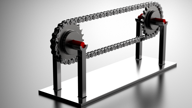 3D printers are widely used for the domestic production of jewelry - necklaces, rings, handbags, etc.
The Fab@Home open project aims to develop general purpose home printers. The devices have been tested in research environments using the latest 3D printing technologies for the production of chemical compounds. The printer can print any material suitable for extrusion from a syringe in the form of a liquid or paste. The development is aimed at the possibility of home production of medicines and household chemicals in remote areas of residence.
Student project OpenReflex resulted in a design for an analog SLR camera suitable for 3D printing.
Clothing
3D printing is gaining ground in the fashion world as couturiers use printers to experiment with swimwear, shoes and dresses. Commercial applications include rapid prototyping and 3D printing of professional athletic shoes - the Vapor Laser Talon for soccer players and New Balance for track and field athletes.
3D bioprinting
EBM titanium medical implants
3D printing is currently being researched by biotech companies and academic institutions. The research is aimed at exploring the possibility of using inkjet/drip 3D printing in tissue engineering to create artificial organs. The technology is based on the application of layers of living cells on a gel substrate or sugar matrix, with a gradual layer-by-layer build-up to create three-dimensional structures, including vascular systems. The first 3D tissue printing production system based on NovoGen bioprinting technology was introduced in 2009year. A number of terms are used to describe this research area: organ printing, bioprinting, computer tissue engineering, etc.
One of the pioneers of 3D printing, research company Organovo, conducts laboratory research and develops the production of functional 3D human tissue samples for use in medical and therapeutic research. For bioprinting, the company uses a NovoGen MMX 3D printer. Organovo believes that bioprinting will speed up the testing of new medicines before clinical trials, saving time and money invested in drug development. In the long term, Organovo hopes to adapt bioprinting technology for graft and surgical applications.
3D printing of implants and medical devices
3D printing is used to create implants and devices used in medicine. Successful surgeries include examples such as titanium pelvic and jaw implants and plastic tracheal splints. The most widespread use of 3D printing is expected in the production of hearing aids and dentistry. In March 2014, Swansea surgeons used 3D printing to reconstruct the face of a motorcyclist who was seriously injured in a road accident.
3D printing services
Some companies offer online 3D printing services available to individuals and industrial companies.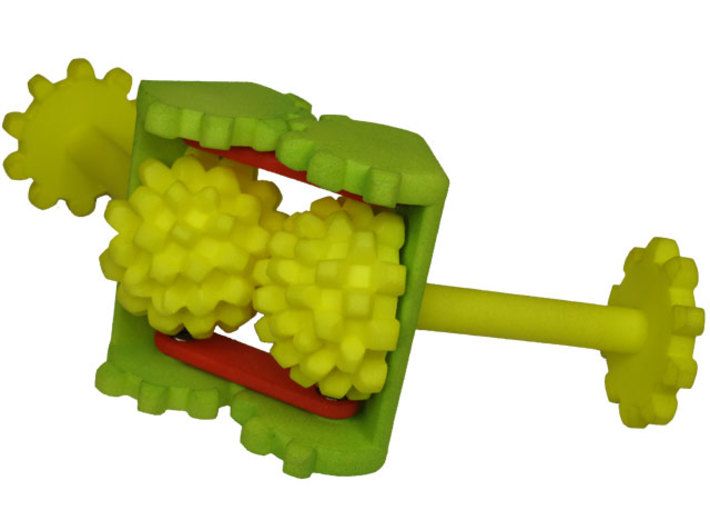 The customer is required to upload a 3D design to the site, after which the model is printed using industrial installations. The finished product is either delivered to the customer or subject to pickup.
Exploring new applications
3D printing makes it possible to create fully functional metal products, including weapons.
Future applications of 3D printing may include the creation of open source scientific equipment for use in open laboratories and other scientific applications - fossil reconstruction in paleontology, the creation of duplicates of priceless archaeological artifacts, the reconstruction of bones and body parts for forensic analysis, the reconstruction of heavily damaged evidence collected from crime scenes. The technology is also being considered for application in construction.
In 2005, academic journals began to publish materials on the possibility of using 3D printing technologies in art. In 2007, the Wall Street Journal and Time magazine included 3D design in their list of the 100 most significant achievements of the year. The Victoria and Albert Museum at the London Design Festival in 2011 presented an exhibition by Murray Moss entitled "Industrial Revolution 2.0: how the material world materializes again", dedicated to 3D printing technologies.
In 2012, a University of Glasgow pilot project showed that 3D printing could be used to produce chemical compounds, including hitherto unknown ones. The project printed chemical storage vessels into which “chemical ink” was injected using additive machines and then reacted. The viability of the technology was proven by the production of new compounds, but a specific practical application was not pursued during the experiment. Cornell Creative Machines has confirmed the feasibility of creating food products using hydrocolloid 3D printing. Professor Leroy Cronin of the University of Glasgow has suggested using "chemical ink" to print medicines.
The use of 3D scanning technology makes it possible to create replicas of real objects without the use of casting methods, which are costly, difficult to perform and can have a destructive effect in cases of precious and fragile objects of cultural heritage.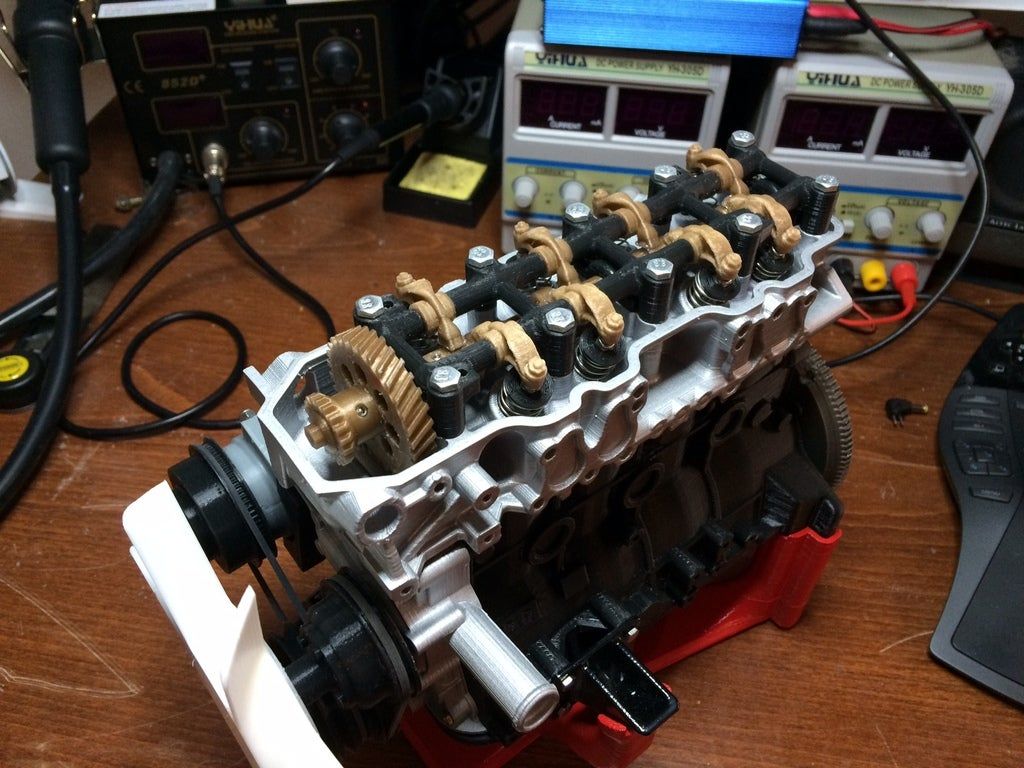
An additional example of 3D printing technologies being developed is the use of additive manufacturing in construction. This could make it possible to accelerate the pace of construction while reducing costs. In particular, the possibility of using technology to build space colonies is being considered. For example, the Sinterhab project aims to explore the possibility of additive manufacturing of lunar bases using lunar regolith as the main building material. Instead of using binding materials, the possibility of microwave sintering of regolith into solid building blocks is being considered.
Additive manufacturing allows you to create waveguides, sleeves and bends in terahertz devices. The high geometric complexity of such products could not be achieved by traditional production methods. A commercially available professional EDEN 260V setup was used to create structures with a resolution of 100 microns. The printed structures were galvanized with gold to create a terahertz plasmonic apparatus.
China has allocated nearly $500 million. for the development of 10 national institutes for the development of 3D printing technologies. In 2013, Chinese scientists began printing living cartilage, liver and kidney tissue using specialized 3D bioprinters. Researchers at Hangzhou Dianqi University have even developed their own 3D bioprinter for this challenging task, dubbed Regenovo. One of Regenovo's developers, Xu Mingeng, said it takes less than an hour for the printer to produce a small sample of liver tissue or a four to five inch sample of ear cartilage. Xu predicts the emergence of the first full-fledged printed artificial organs within the next 10-20 years. That same year, researchers at the Belgian Hasselt University successfully printed a new jaw for an 83-year-old woman. After the implant is implanted, the patient can chew, talk and breathe normally.
In Bahrain, sandstone-like 3D printing has created unique structures to support coral growth and restore damaged reefs.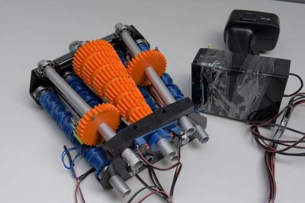 These structures have a more natural shape than previously used structures and do not have the acidity of concrete.
Intellectual property
Section of liver tissue printed by Organovo, which is working to improve 3D printing technology for the production of artificial organs
3D printing has been around for decades, and many aspects of the technology are subject to patents, copyrights, and trademark protection. However, from a legal point of view, it is not entirely clear how intellectual property protection laws will be applied in practice if 3D printers become widely used.
distribution and will be used in household production of goods for personal use, non-commercial use or for sale.
Any of the protective measures may negatively affect the distribution of designs used in 3D printing or the sale of printed products. The use of protected technologies may require the permission of the owner, which in turn will require the payment of royalties.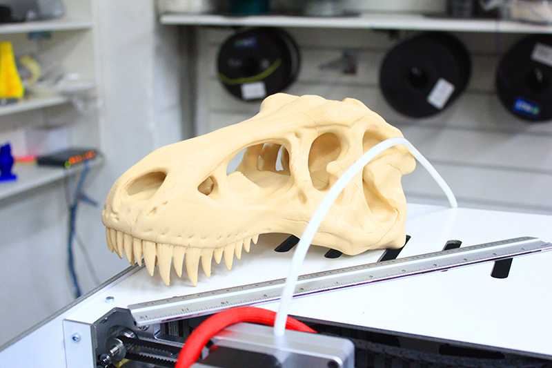
Patents cover certain processes, devices, and materials. The duration of patents varies from country to country.
Often, copyright extends to the expression of ideas in the form of material objects and lasts for the life of the author, plus 70 years. Thus, if someone creates a statue and obtains copyright, it will be illegal to distribute designs for printing of an identical or similar statue.
Influence of 3D printing
Additive manufacturing requires manufacturing companies to be flexible and constantly improve available technologies to stay competitive. Advocates of additive manufacturing predict that the opposition between 3D printing and globalization will escalate as home production displaces trade in goods between consumers and large manufacturers. In reality, the integration of additive technologies into commercial production serves as a complement to traditional subtractive methods, rather than a complete replacement for the latter.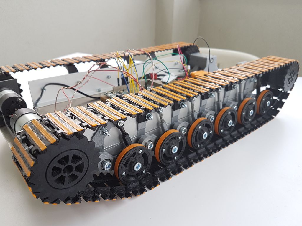
Space exploration
In 2010, work began on the application of 3D printing in zero gravity and low gravity. The main goal is to create hand tools and more complex devices "as needed" instead of using valuable cargo volume and fuel to deliver finished products to orbit.
Even NASA is interested in 3D printing
At the same time, NASA is conducting joint tests with Made in Space to assess the potential of 3D printing to reduce the cost and increase the efficiency of space exploration. Nasa's additive-manufactured rocket parts were successfully tested in July 2013, with two fuel injectors performing on par with conventionally produced parts during operational tests subjecting the parts to temperatures of around 3,300°C and high pressure levels. It is noteworthy that NASA is preparing to launch a 3D printer into space: the agency is going to demonstrate the possibility of creating spare parts directly in orbit, instead of expensive transportation from the ground.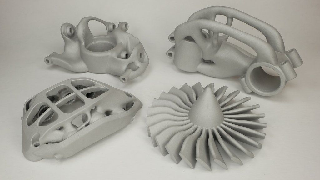
Social change
The topic of social and cultural change as a result of the introduction of commercially available additive technologies has been discussed by writers and sociologists since the 1950s. One of the most interesting assumptions was the possible blurring of boundaries between everyday life and workplaces as a result of the massive introduction of 3D printers into the home. It also points to the ease of transferring digital designs, which, in combination with local production, will help reduce the need for global transportation. Finally, copyright protection may change to reflect the ease of additive manufacturing of many products.
Firearms
In 2012, US company Defense Distributed released plans to create a "design of a functional plastic weapon that could be downloaded and played by anyone with access to a 3D printer." Defense Distributed has developed a 3D printed version of the receiver for the AR-15 rifle, capable of withstanding more than 650 shots, and a 30-round magazine for the M-16 rifle. The AR-15 has two receivers (lower and upper), but legal registration is tied to the lower receiver, which is stamped with a serial number. Shortly after Defense Distributed created the first working drawings for the production of plastic weapons in May 2013, the US State Department requested that the instructions be removed from the company's website.
The distribution of blueprints by Defense Distributed has fueled discussion about the possible impact of 3D printing and digital processing devices on the effectiveness of gun control. However, the fight against the proliferation of digital weapon models will inevitably face the same problems as attempts to prevent the trade in pirated content.
Go to 3D Printing Encyclopedia Homepage
Architectural 3D Printing Modeling Strategy Guide and Software Usage
At a Glance
3D printing brings enormous benefits to the conventional architectural workflow. You can print complex designs without the need for skilled craftsmen, and quickly modify these designs without too much difficulty.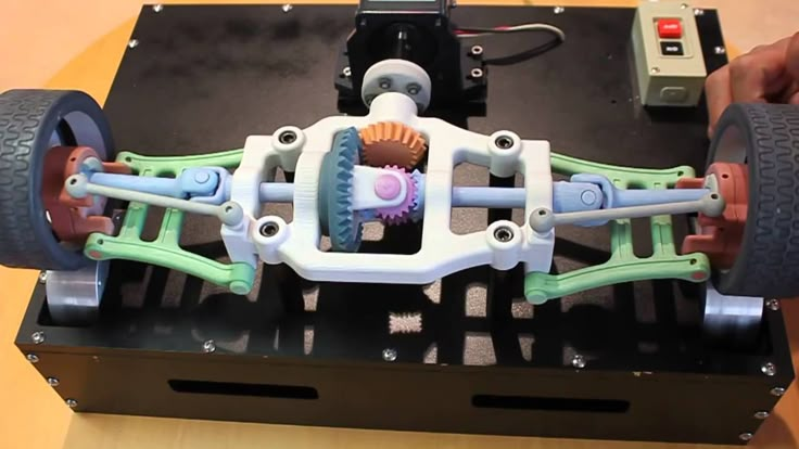 Stereolithographic (SLA) 3D printing delivers incredibly high surface quality and detail, making it suitable for architectural applications. This paper explores modeling strategies and software workflows that enable architects and designers to easily integrate 3D printing into existing design methodology, create best practices based on internal testing by Formlabs and architecture firms, successfully using Form 2 to create 9 models0054
WHAT YOU WILL LEARN:
Design strategies for 3D printed architectural models
Tips for improving your workflow Pre-print processing software
- Building information model (Revit, ArchiCAD)
- Surface modeling (Rhino, SketchUp)
Good post-processing techniques
- Compound
- Finishing
Introduction
The 3D printing market today offers affordable options in both price and scale. While professional-grade technology used to be costly, desktop stereolithography 3D printers allow architects, designers, and model makers to offer high-quality, in-house fabricated parts.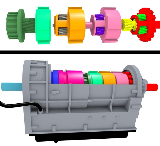
Most models cost less than $10 per part.
3D printing opens the door to creating complex designs with less effort and fewer materials, but the successful transition from a CAD model to a printable file is based on a basic understanding of design for 3D printing. This document will help you understand how standard modeling constraints relate to preparing a file for 3D printing, as well as approaches and decision making for intelligent modeling - from scale selection to design and assembly for post-processing.
To integrate these strategies into existing workflows, this booklet explores ways to approach modeling strategies tactically by examining three of the most common software ecosystems: allows you to include small details even on the smallest models. This example of a small city model has a scale of 1/32″ = 1’ and is completely printed on a Form 2 3D printer. Many small details and parts of this design will take significantly longer if cut and assembled by hand.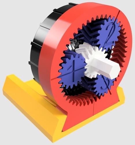 Model from LaneyLA Inc.
This auditorium section was 3D printed as one piece on a black resin Form 2. Model from DLR Group.
Modeling strategy
Architectural models are usually assembled using various materials and components. 3D printers help combine these components into as few separate parts as possible, but assembly manipulation is still necessary for two reasons:
- Build Volume Limitations: Printers with large build volumes are either expensive or compromise on surface quality. Form 2 build volume is 57 x 57 x 69 inches (145 x 145 x 175 mm)
- Need to show interior details or materiality : Some models require components to be separated to show more design information.
DESIGN FOR ASSEMBLY
All 3D models require preparation before they can be sent to the 3D printer. In the case of architectural models for the Form 2, this often involves splitting the model into smaller parts to fit the scope of the Form 2 build. The parts can then be easily joined together by chemical adhesive or mechanical assembly; high precision printing ensures that the parts fit together.
Dimensioning for parts to be separated must take into account the final orientation of the model. Most architectural prints need to be oriented at a 45 degree angle due to floor slabs being considered large horizontal projections. Dividing the model into long, thin parts helps maximize the diagonal length of the build volume while achieving perfect orientation
Strategy overview
There are several strategies for assembling 3D printed models. Your strategy will depend on what you hope to represent with the design, as well as the scale and geometry of the model. Consider the following parameters:
- Need to show internal or external parts
- Easy Split (You want to split the model by the least complex part of the model)
It is necessary to show a certain part of the program: typology, structure, floor layout
| Seam separation | Separation by component |
| Section model | Separation by program |
| Straight cut | Separation by structure |
| Aligners |
Splitting at a seam
STRAIGHT CUT
The easiest way to split a model is with a straight cut. This is a simple command to execute in most CAD software. The bridge model is divided lengthwise using straight cuts into four parts, one of which is shown above. Each support post is inserted into
mating hole that does not require glue. Regardless of which method you choose, if you have a large number of parts (more than 10), it can be helpful to add a unique identifier for each part to help solve the puzzle during assembly.
Pros:
- Least heavy use of CAD
- Greater tolerance for prints that warp or have a higher degree of dimensional change
Cons:
- Assembly requires manually leveling each piece and fixing it in place until the adhesive is fully bonded
Try to print all components in the same orientation so that the layer lines and subsequent dimensional inaccuracies follow the same pattern.
MATCHING TOOLS
Another approach is to add features to the design that will allow the prints to align.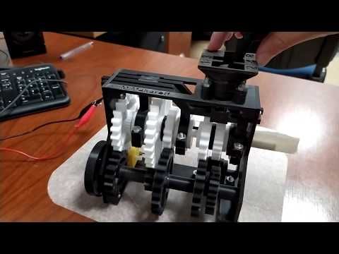 When adding mate fixtures, try to subdivide the model in areas with the least complex geometry. Use the CAD tool of your choice to split your model and add basic alignment fixtures such as slots, pins, grooves, recesses and flanges, or more complex fixtures such as dovetails and cuts that follow existing model curves. In addition, it is important to create a design with ~0.25 mm tolerance between mating parts to prevent additional sanding at the post-printing stage.
Pros:
- Easy alignment Parts that are not accurate
- Easy to assemble (mating parts help create more surface area for adhesion)
- High precision SLA allows tight fit with high tolerance and can be used without adhesive
Cons:
- Parts that are not true to size will not fit well. High fine details are often less accurate.
SECTION MODEL
The separation of the model with a seam has the additional task of showing the section model for structures with irresistible interior details. Initially, the model can be presented as a whole to the client, and then disassembled to reveal interior details as desired. These LaneyLA examples show how the same model conveys different types of information based on open and closed configurations
This model from LaneyLA was printed on a White Resin Form 2.
Model by Stanley Sitetowitz | Natoma Architects Inc.
Since each body block followed the same pattern, it makes sense to simply print one removable block that will allow the customer to understand the typology of the typical device to print as a single block or separate along the seam.
This method usually works for models that are not linear, such as typical building blocks, but complex structures, such as detailed building sections, bridges, pavilions, or airports.
First, break these models down into components that can be 3D printed with minimal supports. This saves post-processing time (removing supports for delicate models can be tedious) and reduces material costs and print times.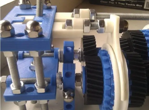
This bridge example demonstrates multiple partitioning methods. First, the model is divided into several parts (Figure a). While they fit the
Form 2 build platform, they require painstaking removal of supports around more delicate areas such as cables and railings.
To solve this problem, each part is broken down into three sub-components: base plate and railing, vertical tensile cables and solar panels on top (figure b). They can be printed with significantly fewer supports, making it easier to finish,
Once completed, the components simply need to be assembled using the alignment functions that were included in the design phase. Smaller parts are also easier to place on a single build platform, with the entire bridge being printed from five 100ml parts.
Model from T.Y. Lin Architects
This site model was created using laser-cut fiberboard. The primary building was 3D printed from clear and white resin. Model by Schwarz Silver Architects
Materials
Materials play an important role in conveying the basic design concept. It is not always necessary to model the exact color and texture of a material, but it can help separate different materials. Dividing a model into its components allows for the display of materiality, as parts can be printed in different materials or individually dyed in different colors.
The transparent façade is illuminated from within, simulating the visual conditions of this site at night.
Formlabs Matte Resins
Black, White and Gray out of the printer have a smooth, opaque finish and provide an excellent neutral palette for architectural models. Gray and white resins are also easy to process and can be finished with just a few coats of paint, as discussed further in the finishing section of this document.
Formlabs Clear Resin is excellent for printing features that mimic translucent materials.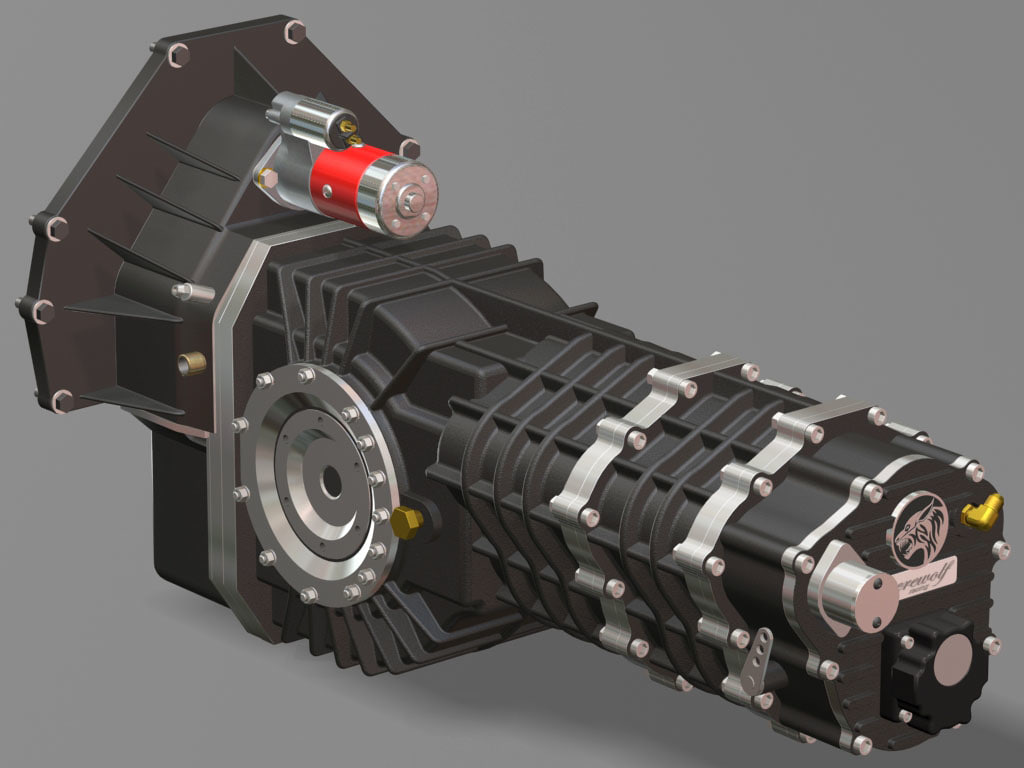 If your model requires more transparency, you can simply dip the printed part in clear resin and let it dry evenly, as described in this article on making clear resin parts. You can also spray any clear coats on the model to increase the transparency and glossiness of the surface.
3D PRINTING AND TRADITIONAL MATERIALS
This model uses the Form 2 to print very fine details such as the cornice, clock and railing. Model by Miles Burke Architectural Models Inc.
Instead of 3D printing an entire building, sometimes it's better to print only complex components. Complex facades, slings and cornice details are excellent candidates for SLA 3D printing. Flat walls, floor slabs and topography can be laser cut or even hand-drawn
This complex façade is parametrically designed from solar trajectory analysis and would be incredibly difficult to fabricate in any other way at this scale.
Software Workflow
Good printing comes from a well-designed 3D model. This section will cover modeling best practices and workflows for printing in some of the most common CAD environments:
Revit, SketchUp and Rhino
CAD software is typically the biggest bottleneck in the transition from drawing to 3D printed model
General workflows
IMZ workflow
905 PreForm
While BIM (Building Information Model) software is popular with architecture firms, it is not always used for direct 3D printing models. There are some high level steps that you can take
take to create a 3D printed model from these programs. This workflow is widely applied to Autodesk Revit or Graphisoft ArchiCAD software, both of which are IMZ parametric modeling programs.
PREPARE THE FILE
STEP 1: Prepare a separate stand-alone file
STEP 2: Component Management: remove ducts, double glazing, HVAC units and internal parts that will not be visible in model
STEP 3: Select all components to be sealed (eg doors, windows, walls, slabs). The parametric nature of the model allows you to simultaneously compact the dimensions of several objects.
EXPORT FILE
Select the scale at which you want to export the file. Select export options depending on the needs of your model:
EXPORT AS STL
Exporting the file as a mesh is very difficult to manipulate, so this is only useful if you don't want to edit any geometry after this step. You can then use your software to correct the mesh of your choice, as well as subdivide the mesh along the main Cartesian planes.
EXPORT AS 3D DWG
Export as surfaces allows you to easily manage and edit geometry in Rhino or SketchUp. This step is recommended for those who want to split the model programmatically or by component, or split by a seam that is not on the normal Cartesian plane. You can then export the STL file from Rhino or SketchUp using the plug-in
EXPORT USING ARCHICAD
Perform a geometry transformation to Morphs and a "consistency check" before exporting the model as STL. When printing in parts, use tool
"Divide" to cut the model for multiple print platforms, if needed. This operation basically creates printable files, but a quick check in mesh repair/analysis software never hurts.
USING STL REVIT EXPORTER
This method automatically removes smaller details such as doorknobs and railings. However, it is not reliable and still often requires some post-processing in other CAD environments before being sent to print.
Surface modeling workflow
AutoCAD → Rhino/SketchUp → Model Diagnostics → PreForm
This workflow is often an easier approach and starts with 2D drawings solely for the purpose of 3D printing
PREPARE FILE STEP 1: Hide unwanted layers
STEP 2: Identify and remove unnecessary elements such as furniture, trees, etc.
EXPORT FILE
STEP 1: Export the simplified drawing from Rhino as DWG
STEP 2: Import into Rhino
STEP 4: Start extruding and trimming until you get the outer shell.
STEP 5: Export as STL STEP 6: Mesh Analysis/Correction STEP 7: Import to PreForm
Note: If the model will be printed in several parts, split it before exporting as STL
THICKNESS WITH RHINO
Instead of parametrically controlling the thickness of components directly in the BIM file, you can also use the BoxEdit component in Rhino.
This allows you to simultaneously scale a number of elements with respect to their center lines. BoxEdit is ideal for models that need to be scaled parallel to three Cartesian axes. Non-uniform scaling is a little trickier.
For non-rectilinear geometries, we suggest converting the part to a mesh and then using the Weaverbird thicken command, which simply offsets any non-standard mesh geometry outward by a given distance. Alternatively, it is possible to "split" complex parts into surfaces and then offset them instead of importing volumes from Revit.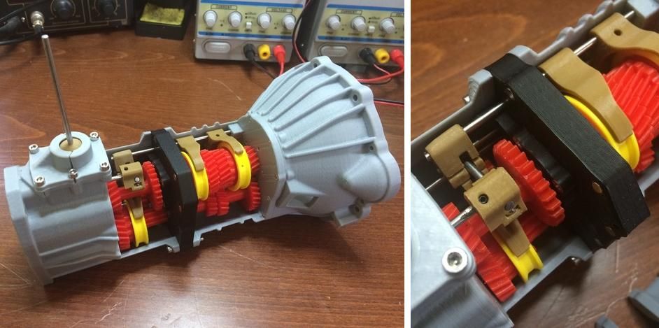
SELECTING SMALL GEOMETRIES WITH RHINO
Another valuable Rhino feature is the SelSmall command, which allows you to select all elements in the Stage that are smaller than a custom bounding box. You can then select those objects and use
BoxEdit for individual scaling or just remove them. This is useful when you are dealing with a file that does not have a well organized layer system.
Although performing a logical connection on all geometries is ideal, often the problem can be solved with simple overlapping geometries. PreForm will interpret them as one closed geometry in most cases, but be sure to check printability with the "slicer" tool in the right pane in PreForm
. CONTINUOUS / LOGICAL JOINT GEOMETRY
Note : PreForm is Formlabs free software that prepares your 3D model for printing in Form 2. Once the part is set up, you can save it as a FORM file for future use in preform.
COMPUTATION WORKFLOW
Although a less common workflow, computational design is slowly being introduced into mainstream architectural workflows. Software such as Grasshopper and Dynamo are used to create parametrically generated geometries that are often so complex that they can only be created with 3D printing.
Since geometries are already easy to manipulate, it's usually best to create a separate component that allows you to easily control the basic dimensions of all thin objects. In this case, it's a simple matter of trial and error; running the exported geometries with a print test (PreForm,
MeshMixer) and resizing until you arrive at a printable file.
Model Diagnosis
All workflows described below share a potential "generic diagnosis". This is an optional (but often necessary) step to ensure that the model is fully printable. Free programs such as Autodesk's MeshMixer and Netfabb are tools that allow you to repair, smooth, cavity, and split 3D print files.
MESH FIX
Formlabs PreForm software uses Netfabb's built-in mesh fix, so NetFabb and MeshMixer must be used for custom fix or to preview problem spots in print. Materialize Magics is a great proprietary tool that covers the entire preprint workflow for a wide range of printer types. The mesh patching software part is most important to the Form 2 print workflow and can save you a decent amount of preparation time. Netfabb has a beautiful built-in model cutter that allows you to effectively split and restore large files along any Cartesian plane.
SPLITTING THE MODEL
You can also split the model in NetFabb, which splits and fixes the split parts into printable volumes. In Rhino, you will need to close open volumes. Be sure to leave a tolerance of ~0.25mm between adjacent parts, this will allow them to be inserted without friction.
See our white paper for tolerances.
PREFORM SLICER
Architectural models are highly detailed and it is often difficult to isolate each print issue. A combination of the above practices and mesh repair software is usually used for almost all problems, but it's always wise to use the PreForm Slicer tool to make sure there are no thin unsupported areas and enclosed volumes (such as rooms with no doors, elevator shafts, and parking spaces) .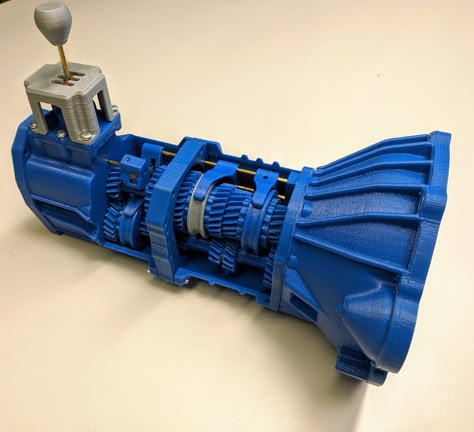
“Building and architecture structures are not meant to be 3D printed, they are meant to be built. This creates problems of scale and complex geometry. By combining Netfabb's powerful mesh repair tools with the precision of the Form 2, you can prototype and visualize designs faster and in more detail, benefiting more for your business and speeding up your project's design review process.”
Matt Lemay. Lead Enterprise Solutions Provider, Autodesk Customer Service
Post-Processing
Joining
The modeling strategy section of this booklet covers some ways of splitting and aligning parts together, but glue is always needed for a secure connection. Architectural parts are bonded in two main ways:
CYANOACRYLATE
Cyanoacrylate (CA or Super Glue) creates a fast, strong enough bond, ideal for small to medium sized parts. CA does not bond dirty surfaces well, so be sure to thoroughly clean the part before applying adhesive to the surface of the model.
POLYMER
For smaller prints, you can use liquid resin as a binder. Dispense a small amount of resin into the tray from a bottle or cartridge, use a dropper or syringe to lift it up, and place it on the surface of the part to be bonded.
Join parts and wipe off any excess resin that may be spilling around the edges. To cure the resin and bond the parts, use a 5 mW laser pen at 405 nm and point it at the bonding area around the parts.
This method creates a chemical bond, just as if the part had been printed on your SLA 3D printer, but only applies to small bonding surfaces because a low power laser pen cannot penetrate the model deep enough to create a strong bond .
FINISHING
Parts printed on Form 2, especially matte standard resins, have a smooth surface as soon as they exit the printer. However, visible areas with supports almost always require sanding. In addition, you can prime and paint parts in any desired color.
GRINDING
Sanding will help you remove the support marks and any remaining inaccuracies from your model. Start by carefully dry sanding the surface of the part using ~150 grit sandpaper to remove large support marks and smooth out the edges of the joint. Once the surface of the part is smooth, wet sand with 320mm sandpaper to remove any remaining layer lines. Move the sandpaper randomly to avoid grain formation.
In most cases these two steps will create a fairly even finish, but you can continue to increase the grit size of the sanding paper by a factor of 2 and use wet sanding on the entire piece until the surface is the desired smoothness.
Once you have finished sanding your model, wash the model in soapy water to remove any dust or debris and dry thoroughly before proceeding to the last step.
The architectural models are very detailed and it is quite difficult to access certain areas with just sandpaper. You can use different sizes of nail files to get to problem areas of the model.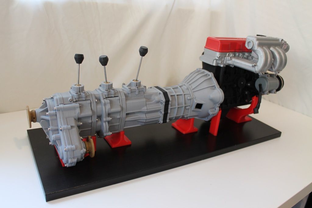
PRIMER AND PAINTING
Priming is required before parts are painted to ensure the paint adheres to the surface. Priming can also make it easier to find areas that require additional finishing. A quick spray of primer over the model makes the support marks very visible, so you can instantly identify areas that need additional sanding.
General plastic primer gray matt shows details very well. Apply it to surfaces in several thin layers for best results. Continue sanding in critical areas, reapply a light coat of primer and repeat this process until the entire part is smooth. Most spray paints work best in warm, slightly damp conditions with no airflow, but always check the specific paint or data sheet for manufacturer's recommendations.
“Models are becoming rarer in a field where photorealistic renderings and virtual reality technology are advancing, but physical models allow architects to test spatial qualities in ways that digital models cannot.