Metal sintering 3d printing
Metal 3D Printing Service for Custom Parts
Back
-
Materials
Materials by Service
Injection MoldingCNC Machining3D PrintingSheet Metal
Materials by Type
PlasticsMetalsElastomers
Related Links
Customer Supplied ResinsColors
Injection Molding Material Alternatives Guide
Struggling with thermoplastic material shortages? We created a detailed guide to resin substitutes for ABS, PC, PP, and other commonly molded thermoplastics.
Download
-
Resources
Design Tips Guides and Trend Reports Success Stories Design Aids Webinars and Trade Shows
Blog Videos FAQs Educators and Students Glossary
Industries Medical Aerospace Automotive Consumer Electronics Industrial Equipment
-
About Us
Who We Are Why Protolabs? Research and Development Cool Idea Award Partnerships Sustainability and Social Impact
Careers Investors Locations Press Procurement
Contact Us
Proto Labs, Inc.
5540 Pioneer Creek Dr.
Maple Plain, MN 55359
United StatesP: 877.479.3680
F: 763.479.2679
E: [email protected]Best-in-Class Online Quoting
After uploading your part design, you'll receive an online quote that includes manufacturing analysis to help improve part manufacturability. Within your quote, you can also adjust quantity and material and see price changes in real-time.
Learn More
Get a QuoteSign In
Get quality metal 3D-printed prototypes and production parts. Request an online quote today.
GET METAL PARTS
Certifications
ISO 9001:2015 | AS9100D | ITAR Registered
Jump to Section→ Capabilities
→ Available Alloys
→ Compare Material Properties
→ Surface Finishes
→ Post-Processing
→ Why Metal 3D Printing?
Direct metal laser sintering (DMLS) is an industrial metal 3D printing process that builds fully functional metal prototypes and production parts in 7 days or less.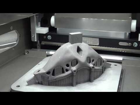 A range of metals produce final parts that can be used for end-use applications.
Metal 3D printing technology is commonly used for:
- Prototyping in production-grade materials
- Complex geometries
- Functional, end-use parts
- Reducing metal components in an assembly
We hope you find this guide helpful. If the file did not download, you can find it here.
Metal 3D Printing Guide
Jump start your metal 3D printing with this guide that covers material selection, design, post-processing, and quality inspections.
United States of AmericaAfghanistanÅland IslandsAlbaniaAlgeriaAmerican SamoaAndorraAngolaAnguillaAntarcticaAntigua and BarbudaArgentinaArmeniaArubaAustraliaAustriaAzerbaijanBahamasBahrainBangladeshBarbadosBelarusBelgiumBelizeBeninBermudaBhutanBolivia, Plurinational State ofBonaire, Sint Eustatius and SabaBosnia and HerzegovinaBotswanaBouvet IslandBrazilBritish Indian Ocean TerritoryBrunei DarussalamBulgariaBurkina FasoBurundiCambodiaCameroonCanadaCape VerdeCayman IslandsCentral African RepublicChadChileChinaChristmas IslandCocos (Keeling) IslandsColombiaComorosCongoCongo, the Democratic Republic of theCook IslandsCosta RicaCôte d'IvoireCroatiaCubaCuraçaoCyprusCzech RepublicDenmarkDjiboutiDominicaDominican RepublicEcuadorEgyptEl SalvadorEquatorial GuineaEritreaEstoniaEthiopiaFalkland Islands (Malvinas)Faroe IslandsFijiFinlandFranceFrench GuianaFrench PolynesiaFrench Southern TerritoriesGabonGambiaGeorgiaGermanyGhanaGibraltarGreeceGreenlandGrenadaGuadeloupeGuamGuatemalaGuernseyGuineaGuinea-BissauGuyanaHaitiHeard Island and McDonald IslandsHoly See (Vatican City State)HondurasHong KongHungaryIcelandIndiaIndonesiaIran, Islamic Republic ofIraqIrelandIsle of ManIsraelItalyJamaicaJapanJerseyJordanKazakhstanKenyaKiribatiKorea, Democratic People's Republic ofKorea, Republic ofKuwaitKyrgyzstanLao People's Democratic RepublicLatviaLebanonLesothoLiberiaLibyaLiechtensteinLithuaniaLuxembourgMacaoMacedonia, the Former Yugoslav Republic ofMadagascarMalawiMalaysiaMaldivesMaliMaltaMarshall IslandsMartiniqueMauritaniaMauritiusMayotteMexicoMicronesia, Federated States ofMoldova, Republic ofMonacoMongoliaMontenegroMontserratMoroccoMozambiqueMyanmarNamibiaNauruNepalNetherlandsNew CaledoniaNew ZealandNicaraguaNigerNigeriaNiueNorfolk IslandNorthern Mariana IslandsNorwayOmanPakistanPalauPalestine, State ofPanamaPapua New GuineaParaguayPeruPhilippinesPitcairnPolandPortugalPuerto RicoQatarRéunionRomaniaRussian FederationRwandaSaint BarthélemySaint Helena, Ascension and Tristan da CunhaSaint Kitts and NevisSaint LuciaSaint Martin (French part)Saint Pierre and MiquelonSaint Vincent and the GrenadinesSamoaSan MarinoSao Tome and PrincipeSaudi ArabiaSenegalSerbiaSeychellesSierra LeoneSingaporeSint Maarten (Dutch part)SlovakiaSloveniaSolomon IslandsSomaliaSouth AfricaSouth Georgia and the South Sandwich IslandsSouth SudanSpainSri LankaSudanSuriNameSvalbard and Jan MayenSwazilandSwedenSwitzerlandSyrian Arab RepublicTaiwan, Province of ChinaTajikistanTanzania, United Republic ofThailandTimor-LesteTogoTokelauTongaTrinidad and TobagoTunisiaTurkeyTurkmenistanTurks and Caicos IslandsTuvaluUgandaUkraineUnited Arab EmiratesUnited KingdomUnited States Minor Outlying IslandsUruguayUzbekistanVanuatuVenezuela, Bolivarian Republic ofViet NamVirgin Islands, BritishVirgin Islands, U.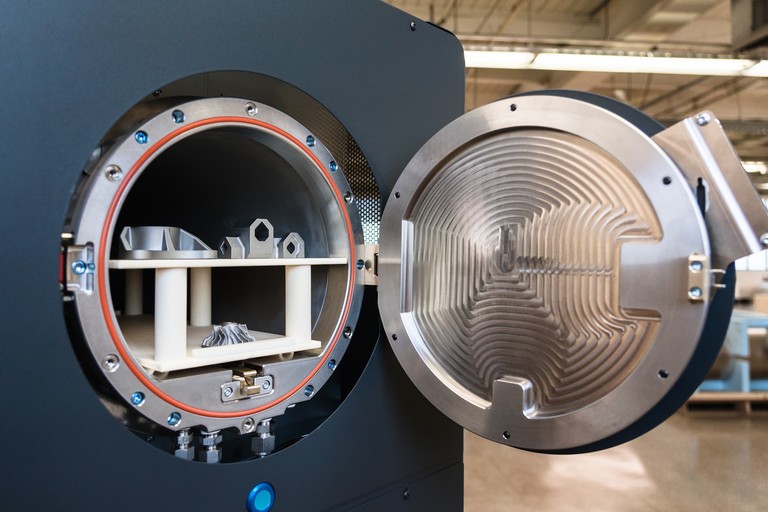 S.Wallis and FutunaWestern SaharaYemenZambiaZimbabwe
I agree to receive email messages containing service updates and Design Tips from Protolabs and its affiliates
Metal 3D Printing Capabilities
Our basic guidelines for metal 3D printing include important design considerations to help improve part manufacturability, enhance cosmetic appearance, and reduce overall production time.
Metal 3D Printing Tolerances
For well-designed parts, tolerances of +0.003 in. (0.076mm) plus 0.1% of nominal length can typically be achieved. Note that tolerances may change depending on part geometry.
Max Dimensions
Layer Thickness
Minimum Feature Size
Tolerances
*At this time, Inconel 718 and Aluminum are the only materials available on our large format, X Line machine
Metal 3D Printing Material Options
Below is our available metal alloys for 3D printing.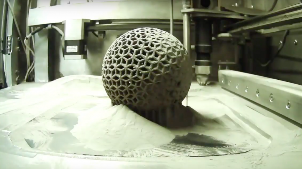 Various heat treatments are available depending on material.
Stainless Steel (17-4 PH)
Stainless Steel 17-4 PH is a precipitation hardened stainless steel that is known for its hardness and corrosion resistance. If needing a stainless steel option, select 17-4 PH for its significantly higher tensile strength and yield strength, but recognize that it has far less elongation at break than 316L. Final parts built 17-4 PH receive vacuum solution heat treatment as well as H900 aging.
Primary Benefits
- Heat treated for full hardness and strength
- Corrosion resistance
LEARN MORE>
Stainless Steel (316L)
Stainless steel 316L is a workhorse material used for manufacturing acid and corrosion resistant parts. Select 316L when stainless steel flexibility is needed; 316L is a more malleable material compared to 17-4 PH. Final parts built in 316L receive stress relief application.
Primary Benefits
- Acid and corrosion resistance
- High ductility
LEARN MORE>
Aluminum (AlSi10Mg)
Aluminum (AlSi10Mg) is comparable to a 3000 series alloy that is used in casting and die casting processes. It has good strength -to-weight ratio, high temperature and corrosion resistance, and good fatigue, creep and rupture strength. AlSi10Mg also exhibits thermal and electrical conductivity properties. Final parts built in AlSi10Mg receive stress relief application.
Primary Benefits
- High stiffness and strength relative to weight
- Thermal and electrical conductivity
LEARN MORE>
Inconel 718
Inconel is a high strength, corrosion resistant nickel chromium superalloy ideal for parts that will experience extreme temperatures and mechanical loading. Final parts built in Inconel 718 receive stress relief application. Solution and aging per AMS 5663 is also available to increase tensile strength and hardness.
Primary Benefits
- Oxidation and corrosion resistance
- High performance tensile, fatigue, creep, and rupture strength
LEARN MORE>
Cobalt Chrome (Co28Cr6Mo)
Cobalt Chrome (Co28Cr6Mo) is a superalloy is known for its high strength-to-weight ratio.
Primary Benefits
- High performance tensile and creep
- Corrosion resistance
LEARN MORE>
Titanium (Ti6Al4V)
Titanium (Ti6Al4V) is a workhorse alloy. Versus Ti grade 23 annealed, the mechanical properties of Ti6Al4V are comparable to wrought titanium for tensile strength, elongation, and hardness. Final parts built in Ti6Al4V receive vacuum stress relief application.
Primary Benefits
- High stiffness and strength relative to weight
- High temperature and corrosion resistance
LEARN MORE>
Compare Material Properties
20 μm = high resolution (HR)
30, 40, and 60 μm = normal resolution (NR)
- US
- Metric
| Materials | Resolution | Condition | Ultimate Tensile Strength (ksi) | Yield Stress (ksi) | Elongation (%) | Hardness |
|---|---|---|---|---|---|---|
| Stainless Steel (17-4 PH) | 20 μm | Solution & Aged (H900) | 199 | 178 | 10 | 42 HRC |
| 30 μm | Solution & Aged (H900) | 198 | 179 | 13 | 42 HRC | |
| Stainless Steel (316L) | 20 μm | Stress Relieved | 82 | 56 | 78 | 90 HRB |
| 30 μm | Stress Relieved | 85 | 55 | 75 | 88 HRB | |
| Aluminum (AlSi10Mg) | 20 μm | Stress Relieved | 39 | 26 | 15 | 42 HRB |
| 30 μm | Stress Relieved | 50 | 33 | 8 | 59 HRB | |
| 40 μm | Stress Relieved | 43 | 27 | 10 | 50 HRB | |
| Cobalt Chrome (Co28Cr6Mo) | 20 μm | As Built | 182 | 112 | 17 | 39 HRC |
| 30 μm | As Built | 176 | 119 | 14 | 38 HRC | |
| Inconel 718 | 20 μm | Stress Relieved | 143 | 98 | 36 | 33 HRC |
| 30 μm | Stress Relieved | 144 | 91 | 39 | 30 HRC | |
| 30 μm | Solution & Aged per AMS 5663 | 208 | 175 | 18 | 46 HRC | |
| 60 μm | Stress Relieved | 139 | 83 | 40 | 27 HRC | |
| 60 μm | Solution & Aged per AMS 5663 | 201 | 174 | 19 | 45 HRC | |
| Titanium (Ti6Al4V) | 20 μm | Stress Relieved | 153 | 138 | 15 | 35 HRC |
| 30 μm | Stress Relieved | 144 | 124 | 18 | 33 HRC |
| Materials | Resolution | Condition | Ultimate Tensile Strength (MPa) | Yield Stress (MPa) | Elongation (%) | Hardness |
|---|---|---|---|---|---|---|
| Stainless Steel (17-4 PH) | 20 μm | Solution & Aged (H900) | 1,372 | 1,227 | 10 | 42 HRC |
| 30 μm | Solution & Aged (H900) | 1,365 | 1,234 | 13 | 42 HRC | |
| Stainless Steel (316L) | 20 μm | Stress Relieved | 565 | 386 | 78 | 90 HRB |
| 30 μm | Stress Relieved | 586 | 379 | 75 | 88 HRB | |
| Aluminum (AlSi10Mg) | 20 μm | Stress Relieved | 268 | 180 | 15 | 46 HRB |
| 30 μm | Stress Relieved | 345 | 228 | 8 | 59 HRB | |
| 40 μm | Stress Relieved | 296 | 186 | 10 | 50 HRB | |
| Cobalt Chrome (Co28Cr6Mo) | 20 μm | As Built | 1255 | 772 | 17 | 39 HRC |
| 30 μm | As Built | 1213 | 820 | 14 | 38 HRC | |
| Copper (CuNi2SiCr) | 20 μm | Precipitation Hardened | 496 | 434 | 23 | 87 HRB |
| Inconel 718 | 20 μm | Stress Relieved | 986 | 676 | 36 | 33 HRC |
| 30 μm | Stress Relieved | 993 | 627 | 39 | 30 HRC | |
| 30 μm | Solution & Aged per AMS 5663 | 1434 | 1207 | 18 | 46 HRC | |
| 60 μm | Stress Relieved | 958 | 572 | 40 | 27 HRC | |
| 60 μm | Solution & Aged per AMS 5663 | 1386 | 1200 | 19 | 45 HRC | |
| Titanium (Ti6Al4V) | 20 μm | Stress Relieved | 1055 | 951 | 15 | 35 HRC |
| 30 μm | Stress Relieved | 993 | 855 | 18 | 33 HRC |
These figures are approximate and dependent on a number of factors, including but not limited to, machine and process parameters.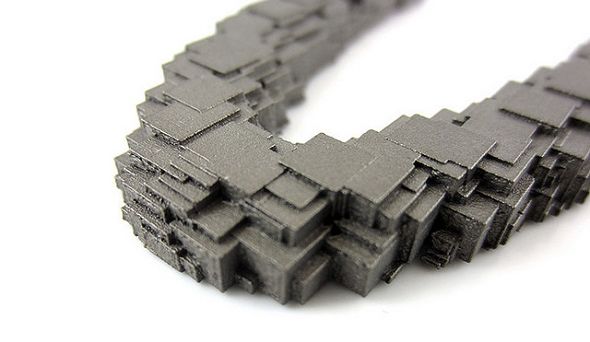 The information provided is therefore not binding and not deemed to be certified. When performance is critical, also consider independent lab testing of additive materials or final parts.
Surface Finish Options
Standard Finish
Expect roughness values of 200 to 400 µin Ra (0.005 to 0.010mm Ra), depending on material and resolution. Support structures are removed and layer lines are visible.
Custom Finish
We offer brushed surfaces in a range of grits and polished mirror finishes. Be sure to indicate if the custom surface finish is for functional or aesthetic purposes so we can best consult you on our custom options.
Post-Processing Capabilities for Metal 3D-Printed Parts
Improve strength, dimensional accuracy, and cosmetic appearance of final metal components with DMLS for production.
Surface Finishing
- 3- and 5-axis milling
- Turning
- Polish (Mirror or Brushed)
- Passivation
- Wire EDM
- Tapping and reaming
Heat Treatments
- Stress relief
- NADCAP heat treatment
- Hot isostatic pressing (HIP)
- Solution annealing
- Aging
Mechanical Testing
- Tensile
- Rockwell Hardness
Powder Analysis & Material
- Traceability
- Chemistry
- Particle size and distribution analysis
Why Use Metal 3D Printing?
See how metal additive manufacturing technology can be used to reduce components within an assembly, fabricate complex geometries, and ultimately save you time and costs.
Click to enlarge
How Does Metal 3D Printing Work?
The DMLS machine begins sintering each layer—first the support structures to the base plate, then the part itself—with a laser aimed onto a bed of metallic powder. After a cross-section layer of powder is micro-welded, the build platform shifts down and a recoater blade moves across the platform to deposit the next layer of powder into an inert build chamber. The process is repeated layer by layer until the build is complete.
When the build finishes, an initial brushing is manually administered to parts to remove a majority of loose powder, followed by the appropriate heat-treat cycle while still fixtured in the support systems to relieve any stresses. Parts are removed from the platform and support structures are removed from the parts, then finished with any needed bead blasting and deburring. Final DMLS parts are near 100 percent dense.
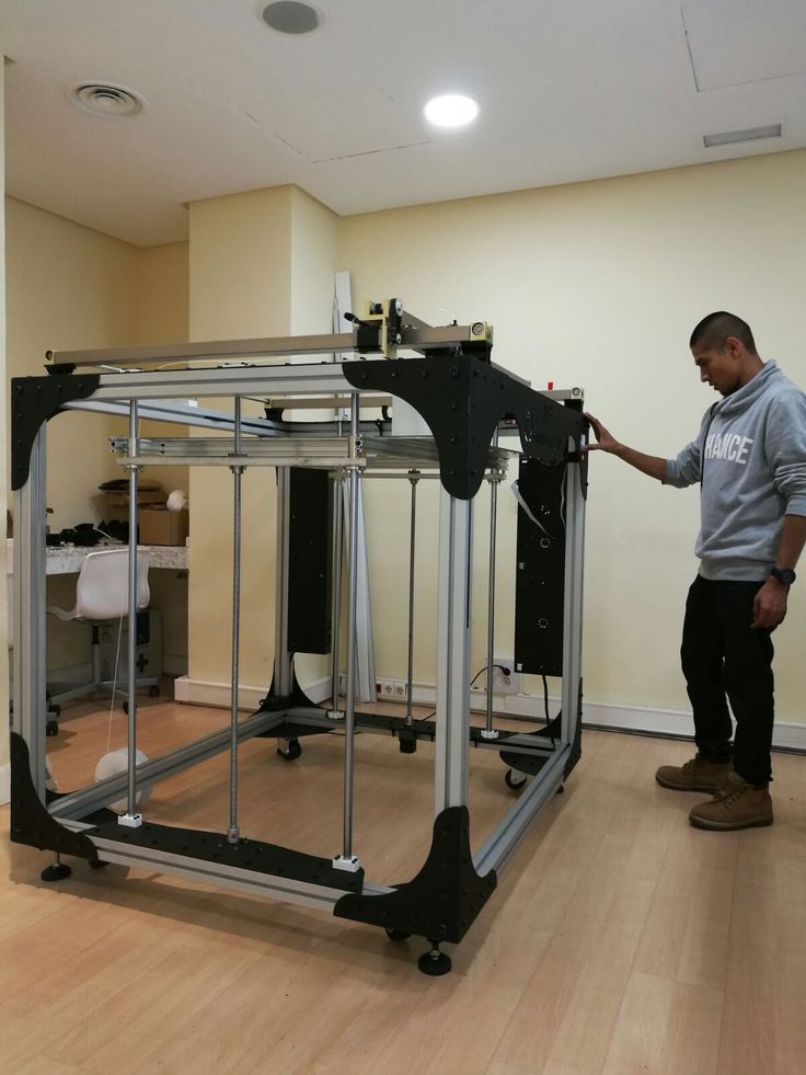
Large Format Metal 3D Printing
We recently added the GE Additive X Line to our fleet of metal 3D printers to build large Inconel 718 and Aluminum (AlSi10Mg) parts. Have a project that might be a good fit? Contact us and we can discuss your requirements.
Learn More >
Metal 3D Printing for Production
Improve strength, dimensional accuracy, and cosmetic appearance for end-use metal components with post-processing options like CNC machining and heat treatments.
Learn More >
Resources
Design Tip
Post-Processing for Metal 3D Printing
Learn how to improve dimensional accuracy, surface roughness, and mechanical properties on metal parts with high-requirement applications.
Read Design Tip
White Paper
Combining Part Assemblies with Additive Manufacturing to Reduce Cost and Increase Performance
How to find the right opportunities to consolidate multi-part assemblies into single components with industrial 3D printing
Read White Paper
Blog
Inconel 718: A Workhorse Material for Additive Manufacturing
Inconel 718 is a go-to material for additive manufacturing of metal parts.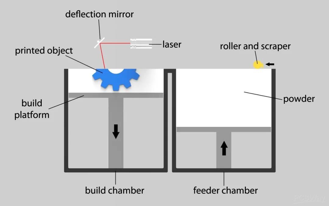
Read Blog
Blog
Large Format 3D Printing for Aluminum and Inconel Parts
When you’re printing really large parts in metal, it’s great to have a choice of materials. Aluminum and Inconel 718 both make a lot of sense, but which one is the best for your application?
Read Blog
Instant quotes on 3D-printed parts
Get A QuoteMetal 3D Printing Process in 3 Steps
Step 1: Print
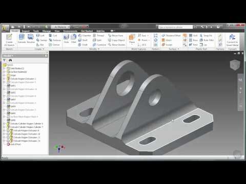
Every 3D printed part starts in CAD, where you design your part. You then export to STL and upload into Eiger. Eiger is a cloud-based slicing and print management system that comes with every Markforged product. Eiger automatically configures your part based on the material and printer you’re using for the job.
When Eiger slices your part, it gets scaled up to account for shrinking and deformation in the downstream processes. Eiger then slices your part into discrete layers and identifies overhanging features, and builds supports and a raft underneath your part.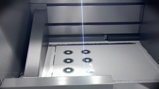
Eiger also monitors the metal part’s progress through each stage of the process. After preparing the print with printing software, it’s time to move to the metal 3D printer itself, the Metal X.
Before starting a print, the Metal X automatically maps and levels the print bed using a unique nozzle touch-off process to ensure the first layer prints properly. The print is built from two materials stored in the heated chamber located at the top of the printer. The first material is the metal and the second is a ceramic release. This filament material is metal powder safely suspended within a two-part plastic binder. The filament is heated and extruded onto the build plate where the part is built up layer by layer. The release material gets extruded as an interface between the part and its supports so that once your part comes out of the furnace, it's easy to remove.
Unlike other metal 3D printing systems, the Metal X process does not use loose metal powder, resulting in a safer and more cost-effective workflow.
The Markforged Metal X system is capable of printing in 17-4 PH Stainless Steel, h23, A2, and D2 Tool Steels, Copper, and Inconel 625, along with several other materials currently in development. You can easily switch between materials with a quick changeover.
Once your part is finished printing, the printer will notify you via email. At this point, you can go to the printer, remove the part from the build sheet, and clear the bed.
At this stage, the printed part is in green form. Next step, we'll be putting it into the wash for the debinding process.
Step 2: Wash
In the wash stage, Markforged’s Wash-1 removes the first stage of the binding material. The green part is taken from the printer and placed into the wash basket, which is then lowered into the solvent.
Wash times will vary during this stage, from a few hours to a few days, depending on the thickest region of your part. After washing is complete, you have a brown part.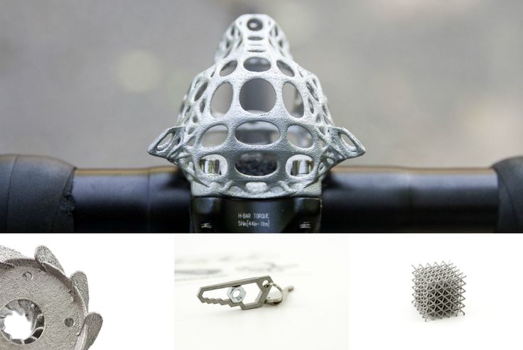 We then move to the sintering process.
Step 3: Sinter
Sintering transforms a brown part into a fully metal part. To do this, the temperature is ramped up slowly to burn away the trace amounts of remaining binding material. As the temperature ramps up closer to the melting point of the material, the metal particles fuse together to create a strong metal part.
The Markforged Sinter-2 is a furnace designed for mid-volume production runs and larger printed parts. The Sinter-2 and other Markforged sintering furnaces use a carbon-free retort to ensure part quality and alloy composition standards are met for finished pieces.
Each run takes about a day and can be monitored remotely using the Eiger software. Once a run is complete, the setter tray with finished metal pieces can be removed from the furnace. Once removed from the raft, these parts are ready for use.
In the furnace, the layer of printed release material between supports, rafts, and your printer part turns to powder. This allows the structure to be tacked to the raft to better control shrinking and accuracy throughout the process, but also an easy release after sintering.
At this stage, your part is fully sintered and ready to be used. It can be post machined, polished or otherwise processed as necessary for the final application, but in many uses the accuracy and strength of the part after this process means its ready for installation.
--
Through this process, you can see how metal 3D printing provides a safe and cost-effective method of metal additive manufacturing. These processes are already driving innovation in lean manufacturing. Learn more about the best materials for metal 3D printing, and the history of 3D printing.
Metal 3D printing
Metal 3D printing can be considered one of the most enticing and technologically challenging areas of additive manufacturing. Attempts to print with metals have been made since the early days of 3D printing technologies, but in most cases they ran into technological incompatibilities.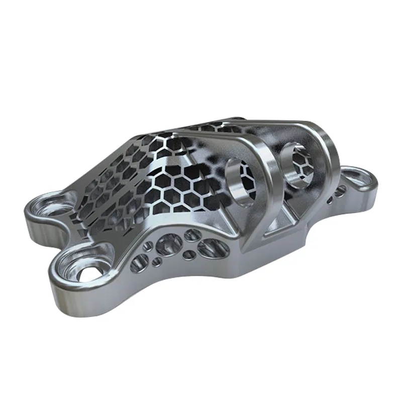 In this section, we will look at technologies that have been tested for printing both composite materials containing metals and pure metals and alloys.
- 1 3D inkjet printing (3DP)
- 2 Lamination Printing (LOM)
- 3 Layered deposition (FDM/FFF)
- 4 Selective laser sintering (SLS) and direct metal sintering (DMLS)
- 5 Selective laser (SLM) and electron beam melting (EBM)
- 6 Direct laser additive construction (CLAD)
- 7 Free electron beam melting (EBFȝ)
3D inkjet printing (3DP)
How 3D inkjet printers (3DP) work
Inkjet 3D printing is not only one of the oldest additive manufacturing techniques, but also one of the most successful in terms of using metals as consumables . However, it is necessary to immediately clarify that this technology allows you to create only composite models due to the technological features of the process.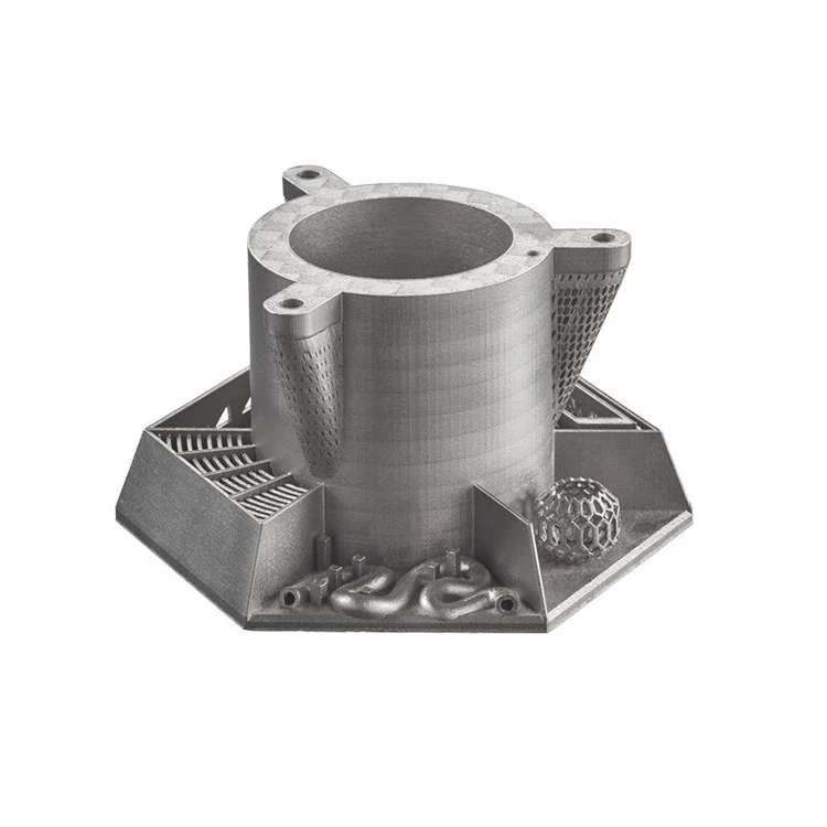 In fact, this method allows you to create three-dimensional models from any materials that can be processed into powder. The binding of the powder is carried out using polymers. Thus, finished models cannot be called fully "metal".
At the same time, there is the possibility of converting composite models into all-metal ones due to heat treatment in order to melt or burn out the binder material and sinter metal particles. The models obtained in this way do not have high strength due to porosity. An increase in strength is possible due to the impregnation of the resulting all-metal model. For example, it is possible to impregnate a steel model with bronze to obtain a stronger structure.
Models obtained in this way, even with metal impregnation, are not used as mechanical components due to their relatively low strength, but are actively used in the jewelry and souvenir industry.
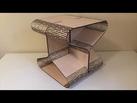
Lamination printing (LOM)
How 3D printers using lamination technology (LOM) work
models.
Metallic foil can also be used as a consumable.
The resulting models are not all metal, as their integrity is based on the adhesive used to bond the consumable sheets.
The advantage of this technology is the relative cheapness of production and the high visual similarity of the resulting models with all-metal products. Typically, this method is used for layout.
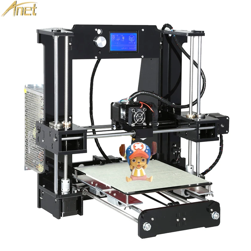
FDM/FFF
Model made with BronzeFill before and after polishing
The most popular 3D printing method has also made use of metals as consumables. Unfortunately, attempts to print with pure metals and alloys have so far not led to significant success. The use of refractory metals runs into quite predictable problems with the choice of materials for the construction of extruders, which, by definition, must withstand even higher temperatures.
Printing with fusible alloys (for example, tin) is possible, but does not give enough high-quality output for practical use.
Thus, in recent years, the attention of consumables developers has switched to composite materials, similar to inkjet printing. A typical example is BronzeFill, a composite material consisting of thermoplastic (details not disclosed, but apparently PLA plastic is used) and bronze powder. The resulting models have a high visual similarity with natural bronze and can even be polished to a high gloss. Unfortunately, the physical and chemical properties of finished products are limited by the parameters of the thermoplastic binder, which does not allow classifying such models as all-metal.
Nevertheless, such materials can be used not only in the creation of models, souvenirs and art objects, but also in industry. Thus, the experiments of enthusiasts have shown the possibility of creating conductors and shielding materials using thermoplastics with a metal filler. The development of this direction can make it possible to print electronic circuit boards.
Selective laser sintering (SLS) and direct metal sintering (DMLS)
The most common method for creating all-metal 3D models involves the use of laser machines for sintering metal powder particles. This technology is referred to as Selective Laser Sintering or SLS. It should be noted that SLS is used not only for working with metals, but also with thermoplastics in powder form. In addition, metallic materials are often coated with more fusible materials to reduce the required power of laser emitters. In such cases, finished metal models require additional sintering in furnaces and impregnation to increase strength.
A variation of the SLS technology is Direct Metal Laser Sintering (DMLS), which, as the name implies, is focused on working with pure metal powders. These plants are often equipped with sealed working chambers filled with an inert gas for working with metals subject to oxidation, such as titanium. In addition, DMLS printers necessarily apply consumable heating to a point just below the melting point, which saves on the power of laser systems and speeds up the printing process.
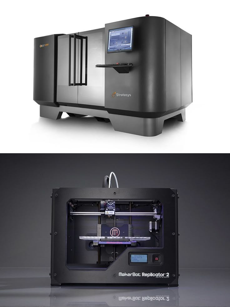
SLS, DLMS and SLM systems
The laser sintering process begins with the application of a thin layer of heated powder to the work platform.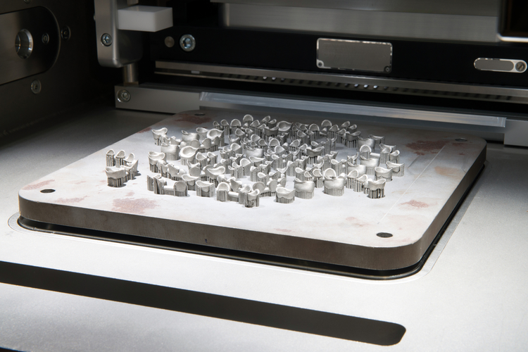 The thickness of the applied layers corresponds to the thickness of one layer of the digital model. Then the particles are sintered between themselves and with the previous layer. Changing the trajectory of the laser beam is carried out using an electromechanical system of mirrors.
When a layer is drawn, the excess material is not removed, but serves as a support for subsequent layers, which allows you to create models of complex shapes, including hinged elements, without the need to build additional support structures. This approach, coupled with high accuracy and resolution, makes it possible to obtain parts that require almost no machining, as well as solid parts of a level of geometric complexity that is unattainable by traditional production methods, including casting.
Laser sintering allows you to work with a wide range of metals, including steel, titanium, nickel alloys, precious materials, etc. The only drawback of the technology can be considered the porosity of the resulting models, which limits the mechanical properties and does not allow achieving strength at the level of cast analogues.
Selective Laser (SLM) and Electron Beam Melting (EBM)
Despite the high quality of the patterns produced by laser sintering, their practical application is limited by the relatively low strength due to porosity. Such products can be used for rapid prototyping, prototyping, jewelry production and many other tasks, but are of little use for the production of parts that can withstand high loads. One solution to this problem has been the conversion of direct metal laser sintering (DMLS) technology to laser melting additive manufacturing (SLM) technology. In fact, the only fundamental difference between these methods is the degree of heat treatment of the metal powder: SLM technology is based on complete melting to obtain homogeneous models that are practically indistinguishable in physical and mechanical properties from cast counterparts.
An example of a titanium implant made using electron beam melting (EBM) technology
A parallel method that has achieved excellent results is electron beam melting (EBM). At the moment, there is only one manufacturer that creates EBM printers - the Swedish company Arcam.
EBM achieves accuracy and resolution comparable to laser melting, but with some advantages. Thus, the use of electron guns makes it possible to get rid of the delicate electromechanical mirror systems used in laser systems. In addition, the manipulation of electron beams using electromagnetic fields is possible at speeds that are incomparably higher compared to electromechanical systems, which, coupled with an increase in power, makes it possible to achieve increased productivity without significantly complicating the design. Otherwise, the design of SLM and EBM printers is similar to laser metal sintering machines.
Ability to work with a wide range of metals and alloys allows you to create small batches of specialized metal parts that are almost as good as samples obtained using traditional production methods. There is no need to create additional tools and infrastructure, such as molds and furnaces.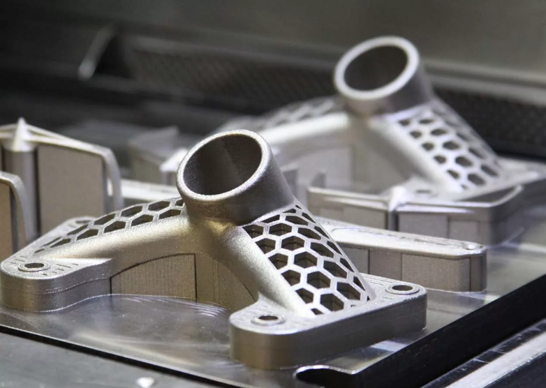 Accordingly, significant savings are possible in prototyping or small-scale production.
Laser and electron beam melting machines have been successfully used to produce items such as orthopedic titanium prostheses, gas turbine blades and jet engine injectors, among others.
Direct Laser Additive Building (CLAD)
How CLAD machines work
Not so much a 3D printing technology as a "3D repair" technology. The technology is used exclusively at the industrial level due to the complexity and relatively narrow specialization.
CLAD is based on the deposition of metal powder on damaged parts with immediate laser welding. The positioning of the "print head" is carried out along five axes: in addition to moving in three planes, the head has the ability to change the angle of inclination and rotate around the vertical axis, which allows you to work at any angle.
Such devices are often used to repair large items, including manufacturing defects.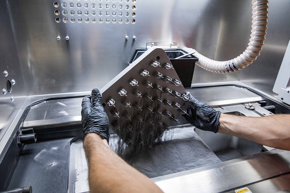 For example, the installations of the French company BeAM are used to repair aircraft engines and other complex mechanisms.
Complete CLAD units use a sealed inert atmosphere working chamber for titanium and other oxidizable metals and alloys.
Free electron beam melting (EBFȝ)
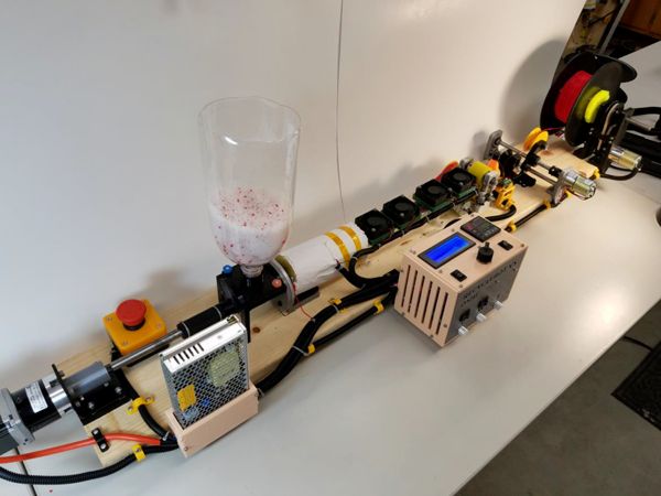
How EBF printers work
Technology developed by NASA for use in zero gravity. Since the absence of gravity makes working with metal powders almost impossible, EBFȝ technology involves the use of metal threads.
The build process is similar to Fused Deposition 3D printing (FDM), but using an electron beam gun to fuse the consumable.
This technology will allow the creation of metal spare parts in orbit, which will significantly reduce the cost of delivering parts and provide the ability to quickly respond to emergency situations.
Go to the main page of the Encyclopedia of 3D Printing
Direct Metal Laser Sintering (DMLS)
- 1 DMLS Technology
- 2 Advantages and disadvantages
- 3 Application
- 4 Materials
- 5 3D Printing Technologies
DMLS Technology
Direct Metal Laser Sintering (DMLS) is a metal additive manufacturing technology developed by EOS in Munich. DMLS is often confused with the similar technologies of selective laser sintering ("Selective Laser Sintering" or SLS) and selective laser melting ("Selective Laser Melting" or SLM).
The process involves using 3D STL models as blueprints for building physical models. The three-dimensional model is subject to digital processing for virtual separation into thin layers with a thickness corresponding to the thickness of the layers applied by the printing device. The finished "construction" file is used as a set of drawings during printing. As a heating element for sintering metal powder, fiber-optic lasers of relatively high power, about 200 W, are used. Some devices use more powerful lasers with faster scanning (i.e. moving the laser beam) for higher performance. Alternatively, it is possible to increase productivity by using multiple lasers.
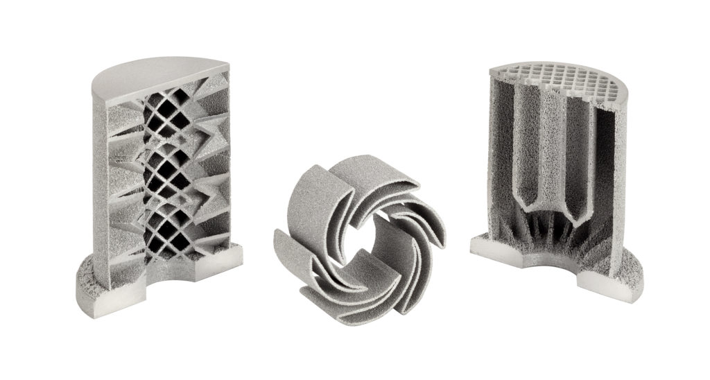
DMLS allows you to create one-piece metal parts of complex geometric shapes
Powder material is fed into the working chamber in the quantities required to apply one layer.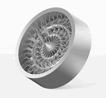 A special roller levels the fed material into an even layer and removes excess material from the chamber, after which the laser head sinters fresh powder particles between themselves and with the previous layer according to the contours defined by the digital model. After the completion of the layer drawing, the process is repeated: the roller feeds fresh material and the laser starts to sinter the next layer. An attractive feature of this technology is the very high print resolution - about 20 microns on average. For comparison, the typical layer thickness in hobby and consumer printers using FDM/FFF technology is on the order of 100 microns.
Another interesting feature of the process is that there is no need to build supports for overhanging structural elements. The green powder is not removed during printing, but remains in the working chamber. Thus, each subsequent layer has a supporting surface. In addition, unused material can be collected from the build chamber after printing is completed and reused. DMLS production can be considered virtually waste-free, which is important when using expensive materials such as precious metals.
The technology has practically no restrictions on the geometric complexity of construction, and the high accuracy of execution minimizes the need for mechanical processing of printed products.
Advantages and disadvantages
DMLS technology has several advantages over traditional manufacturing methods. The most obvious is the possibility of rapid production of geometrically complex parts without the need for machining (the so-called "subtractive" methods - milling, drilling, etc.). Production is practically waste-free, which distinguishes DMLS from subtractive technologies. The technology allows you to create several models at the same time with a limitation only on the size of the working chamber. Building models takes about several hours, which is incommensurably more profitable than the casting process, which can take up to several months, taking into account the full production cycle. On the other hand, parts produced by laser sintering do not have solidity, and therefore do not achieve the same strength values as cast samples or parts produced by subtractive methods.
At the moment, DMLS machines are used only in professional environments due to the high cost.
DMLS is actively used in industry due to the ability to build internal structures of solid parts, inaccessible in complexity to traditional production methods. Details with complex geometry can be made as a whole, and not from component parts, which favorably affects the quality and cost of products. Since DMLS does not require special tools (such as molds) and does not generate large amounts of waste (as is the case with subtractive methods), the production of small batches with this technology is much more profitable than with traditional methods.
Application
DMLS technology is applied to the production of small and medium-sized finished products in various industries, including aerospace, dental, medical, etc.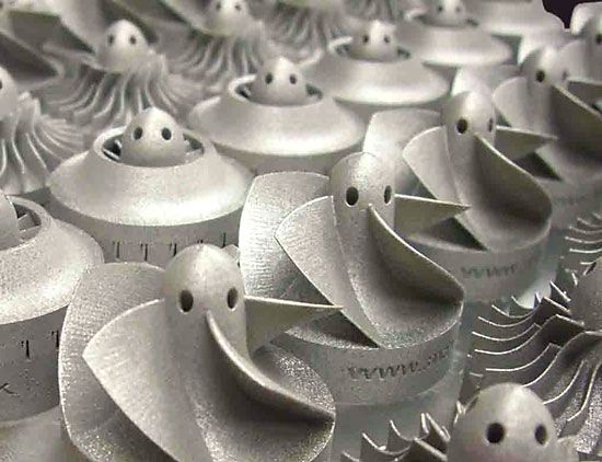 The typical size of the construction area of existing plants is 250x250x250mm, although there are no technological restrictions on size - it is only a matter of cost devices. DMLS is used for rapid prototyping, reducing the development time of new products, as well as in production, reducing the cost of small batches and simplifying the assembly of complex geometric shapes.
Photos of Super Draco rocket engine parts released by Space X founder Elon Musk
Northwest Polytechnic University of China uses DMLS systems to produce aircraft structural components. Research conducted by EADS also indicates cost and waste reductions when using DMLS technology to produce complex designs in single or small batches.
On September 5, 2013, Elon Musk posted photos of a Super Draco rocket motor part made from Inconel nickel-chromium heat-resistant alloy using an EOS printer.
Materials
Almost all metals and alloys in powder form can be used as consumables.