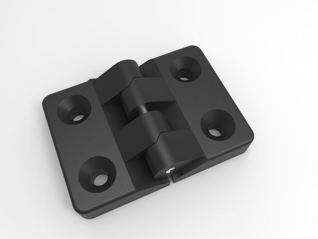
3D print living hinge
How to design living hinges for 3D printing
This article discusses the advantages of living hinges and present-day design rules and material recommendations when using 3D printing to produce living hinges.
Living hinges are a simple, low-cost method of connecting two rigid plastic parts with a flexible joint. This article discusses the advantages of living hinges and present-day design rules and material recommendations when using 3D printing to produce living hinges.
What is a living hinge?
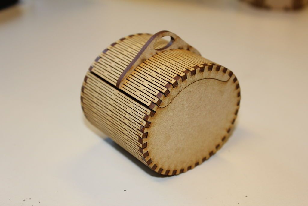
A living hinge is a thin, flexible web of plastic that connects two or more rigid sections. Typically, the larger rigid section and the living hinge are made from a single continuous strand of plastic. The low cost and simplicity of living hinges make them a popular choice for many applications. Living hinges can be found on everything from drink and shampoo bottles to workshop storage containers and food packaging. Living hinges and their associated rigid sections are manufactured almost exclusively with injection molding.
What are the advantages and disadvantages of living hinges?
-
Low-cost: Because of their simplicity, living hinges are usually cheaper than other hinge types.
-
Durability: Living hinges are specifically designed for repeated use. They experience very little friction when opened and closed, typically leading to a long lifespan.
-
Reduced inventory: Living hinges are designed to be integrated into parts, eliminating the need for extra components.
-
Appearance: Compared to other connection options (assembled hinges, snap-fit connectors, etc.), living hinges are an aesthetically pleasing, non-obtrusive solution.
The main disadvantage of living hinges is their load-bearing limitation.
Can you use 3D printing to make living hinges?
While injection molded living hinges are designed to withstand thousands of cycles without breaking, the nature of 3D printing—anisotropic, brittle layer-by-layer construction—means that 3D-printed living hinges are usually used for prototyping or proof-of-concept models that only require a few cycles. This makes 3D-printed living hinges best suited for the verification of a design before investing in expensive injection molded tooling.
What are the advantages of 3D printing a living hinge?
-
There is no need for expensive tooling.
-
The design does not need to incorporate features essential to injection molded parts, such as gates, runners or sprues.
-
Designs can be easily altered and iterated to achieve optimal design.
-
3D-printed parts can be produced quickly, accelerating the design process.
As with other 3D-printed features, performance varies according to design, material, printer calibrations and layer thickness. That often makes finding the optimal living hinge for a specific design and technology an iterative process. This section offers several design recommendations as a starting point.
Print direction
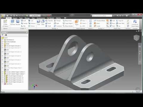
Due to the additive, layer-by-layer nature of 3D printing, the produced parts are typically anisotropic. To improve the likelihood of a living hinge’s successful performance, parts should be oriented so that the hinge width rather than length is built up one layer at a time. This often requires producing the part in the vertical build direction (as shown in the image below).
Hinge geometry
For most prototyping applications, simply printing a thin strip of material is adequate if the hinge only needs to function for several cycles. If a greater number of cycles is required, the hinge geometry can be optimized.
A closing hinge is subjected to bending: the outer surface is placed under tension and stretches, while the inner surface compresses. To accommodate this, a good living hinge should be designed to have a long, curved outer surface and a short inner surface. The image below illustrates a standard injection molded living hinge with dimensions in millimeters.
These are recommended dimensions for an injection-molded living hinge design.For 3D printing, use more material and a stiffer hinge to improve the number of cycles before failure. Though keep in mind that hinge thickness increases the force of tensile stress on the outer surface.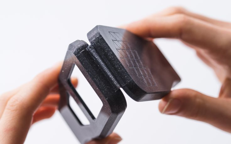 The figure below shows the dimensions of an FDM-printed living hinge that achieved 25 cycles before failure.
Each type of 3D printing technology has its own set of best practices when it comes to materials and processes used to optimize the production of a part to meet the engineer’s requirements. This is why design rules often differ for each technology.
Living hinges in FDM printing
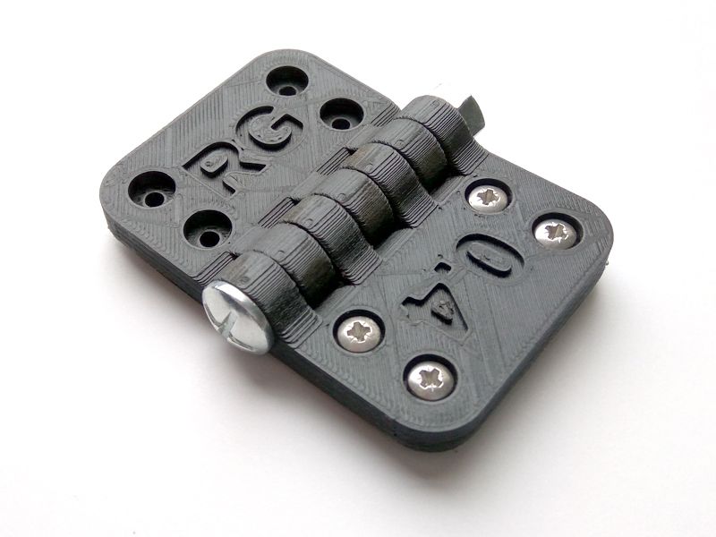
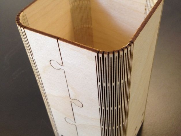
When you are designing a living hinge for FDM, you want to be able to print the hinge with a single strand of thermoplastic integrated into the rigid sections of the build (as shown in the image below).
Depending on the design, a specific orientation might have to be selected to ensure the continuous strand of filament which might result in the need for more support material. If support material is required, it will increase the build’s costs and time.
Some dual extrusion FDM printers offer the option to print the hinge section in a secondary flexible material (such as TPU). This further improves hinge performance and the number of cycles before failure. Build orientation remains an important consideration for these materials.
Recommended hinge specifications: 0.4-0.6mm thick with a minimum of two layers
Living hinges for SLS printing
While SLS parts are less susceptible than FDM to delamination, build direction will still impact the life cycle of SLS-printed living hinges. Hinges produced with SLS typically last around 30-50 cycles before failure.
Recommended hinge specifications: 0.3-0.8mm thick and a minimum of 5mm long
What are the options for post-processing living hinges?
After printing, living hinges can be annealed to increase the number of cycles before failure.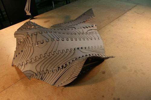 This can be achieved by heating—a common method is submerging the hinge in boiling water—and then working it back and forth at the elevated temperature before leaving in the closed position to cool. The effect of this procedure greatly depends on the material used and the geometry of the hinge.
Which materials are used for manufacturing living hinges?
Injection molded living hinges are made almost exclusively from polyethylene and polypropylene plastic. Both materials are flexible and soft, with a relatively low melting point.
For 3D printing, materials that have a high elongation before breaking and good tear resistance are optimal. The recommended materials for each process described above are summarized in the table below.
| Technology | Recommended material |
|---|---|
| FDM | Nylon 12 |
| FDM (multi-material) | Rigid section: any rigid thermoplastic Living hinge: TPU, SemiFlex, NinjaFlex |
| SLS | PA12 or PA11 |
| Material jetting | Simulated polypropylene |
| Material jetting (multi-material) | Rigid section: any rigid photopolymer Living hinge: TangoBlack, VisiJet elastomers |
Living hinge best practices
-
3D printed living hinges are best suited for proof-of-concept designs before investing in expensive injection molded tooling.
-
Living hinge geometry should have a long outer surface path and a short internal path.
-
Hinge dimensions and materials that best suit 3D-printing technologies for producing living hinges are summarized in the table below.
| Technology | Dimensions | Material |
|---|---|---|
| FDM | 0.4-0.6mm | Nylon 12 |
| SLS | 0.3-0.8mm thick and a minimum 5mm long | PA12 or PA11 |
| Material jetting | 0.4-0.8mm thick | Simulated polypropylene |
Ready to transform your CAD file into a custom part? Upload your designs for a free, instant quote.
Get an instant quoteHow to Design 3D-Printed Hinges
Back
-
Materials
Materials by Service
Injection MoldingCNC Machining3D PrintingSheet Metal
Materials by Type
PlasticsMetalsElastomers
Related Links
Customer Supplied ResinsColors
Injection Molding Material Alternatives Guide
Struggling with thermoplastic material shortages? We created a detailed guide to resin substitutes for ABS, PC, PP, and other commonly molded thermoplastics.
Download
-
Resources
Design Tips Guides and Trend Reports Success Stories Design Aids Webinars and Trade Shows
Blog Videos FAQs Educators and Students Glossary
Industries Medical Aerospace Automotive Consumer Electronics Industrial Equipment
-
About Us
Who We Are Why Protolabs? Research and Development Cool Idea Award Partnerships Sustainability and Social Impact
Careers Investors Locations Press Procurement
Contact Us
Proto Labs, Inc.
5540 Pioneer Creek Dr.
Maple Plain, MN 55359
United StatesP: 877.479.3680
F: 763.479.2679
E: [email protected]Best-in-Class Online Quoting
After uploading your part design, you'll receive an online quote that includes manufacturing analysis to help improve part manufacturability. Within your quote, you can also adjust quantity and material and see price changes in real-time.
Learn More
Get a QuoteSign In
Learn how additive manufacturing can help you quickly prototype and improve your living hinge designs
Prototypes 3D printed with selective laser sintering (SLS) or Multi Jet Fusion (MJF) often include living hinges that will later be injection molded. Injection molding can create living hinges that are extremely thin yet still have a long lifespan. While it is possible to create robust and functional living hinges in SLS and MJF, more care needs to be taken in the design stage. This may even require that the hinge be designed one way during the prototyping stage, and then redesigned before moving to injection molding.
The first principle to keep in mind when designing a living hinge is that it needs to be the weakest area of the part. If the living hinge is roughly the same thickness as the rest of the geometry, then the part will distort and flex when attempting to use the hinge.
| WHY 3D PRINTING FOR LIVING HINGES? |
|---|
|
The force needed to bend a hinge is proportional not only to the thickness of the hinge, but also its width. Consider the possibility of modifying a hinge to several smaller hinges. For example, turning a 0.8 in. hinge into three 0.2 in. hinges and leaving 0.1 in. in between each hinge will not only extend the functional life of the part—if one of many hinges eventually fails, the part may still be usable—but could also improve the performance of the part. That's because less force is needed to operate the hinge and therefore less stress is placed on the clasps, snaps, and the geometry as a whole.
Note that a living hinge will act somewhat like a spring and will exert constant tension on the snaps, clasps, or whatever fastener is holding the part in the flexed position. These fasteners need to be robust enough to oppose the spring-like force of the hinge.
We recommend using Multi Jet Fusion for 3D-printed parts with living hinges due to the technology's minimum feature size of 0.02 in.
Materials for 3D-Printed Living Hinges
When 3D printing parts with living hinges, the most suitable nylon material is PA 12 available in MJF. Hinges can also be made from SLS materials PA 850 Black, and less preferably PA 650, however they will most likely have a shorter lifespan and greater care will be needed in designing them as well as the surrounding part.
We recommend avoiding PA 614 and PA 620 MF for parts with living hinges as the nylon is too stiff and will snap rather than bend. And while you could technically build a living hinge in an elastomer like TPU, the material will rarely be appropriate for the rest of the geometry.
How to Calculate Living Hinge Length
Living hinges are under constant stress when in use. One side of the hinge is under compression, while the other side will be under tension. Because of this, living hinges should be as thin as possible. This means that the thickness of the hinge should be the minimum feature size of the technology (0.02 in. for MJF and 0.03 in. for SLS). This is one of the reasons why MJF is the superior additive manufacturing technology for living hinges.
The formula L=πR is the ideal relationship between hinge length and placement. This allows the hinge to form a semicircle when in the closed position. Following this formula will evenly distribute the stress along the hinge and minimize stress at the attachment points. The following image demonstrates the relationship between hinge length and placement.
In Figure 1:
- A – Indicates the center of the thickness of the living hinge.
- B – Indicates the mating surfaces of the part.
- R – Indicates the distance from the mating surface (B), down the side of the part, to the center line of the living hinge (A). This will become the bend radius of the flexed hinge.

- L – Indicates the length of the hinge.
- Black – Indicates a cross section of the part/hinge in the unflexed or open position.
- Yellow – Indicates a cross section of the part/hinge in the flexed or closed position.
If the hinge is too short or the distance R down the wall to the attachment point is too large (L < πR) the hinge will be under tension in the closed position with the stress concentrated at the attachment points as shown in figure 2.1. If the hinge is too long or the attachment points are too close to the mating surface (L > πR), stress will be concentrated at the attachment points as well as the middle of the hinge. This also reduces the functionality of the part, as the excess hinge material will act as a spring, prying apart the mating surfaces as shown in figure 2.2.
With these concepts in mind, we have found that MJF can build living hinges with good results after annealing down to length L=0.05 in. using the formula L=πR. Meaning that the minimum distance for R in the formula is 0.016 in. Due to how the outside of the hinge stretches relative to the center line of the hinge, smaller hinges (shorter length in the formula L=πR) put more stress on the material than larger hinges.
Larger hinges will put less stress on the material, and will therefore tend to have a longer lifespan. However, at some point the hinge becomes too large and may actually decrease the functionality and aesthetics of the part simply because of the size of the hinge feature.
A Formula for Right-Angle and Other Living Hinges
Up to this point we’ve only discussed hinges that have had a bend of 180 degrees; however, all of these principles can apply to any degree of bend, like a 90 degree hinge, for instance. So what’s the general rule for hinges of all bends?
In the case of a bend of 180 degrees (Figure 3), it is half of the circumference of a circle. So for a bend of 90 degrees, the hinge needs to become a quarter of the circumference of a circle. A general formula for the length of a living hinge given its bend radius (or vice versa), needs to use our previous formula: L=πR.
But since this gives the correct answer for a bend of 180 degrees, we need to take into account how much of 180 the bend degree in question is. In other words, we need to divide it by 180. A formula that can be applied to all bends is L=(Bend°/180)πR.
There is no guaranteed number of flex cycles your hinge will be able to withstand, but following these guidelines will help maximize the longevity of your 3D printing designs with hinges. If you need to discuss your 3D printing design in detail, contact our applications engineers at 877-479-3680 or [email protected].
Dolls on a 3d printer: 3d model of an articulated bjd
Creating beautiful well-detailed dolls is a rather long and laborious process. 3D printing technology will help simplify it. It will allow you to create three-dimensional articulated dolls using a printer. Consider how such dolls differ from ordinary ones, how they are created and what are the advantages and disadvantages of such products.
BJD-dolls on a 3D printer
BJD (ball-jointed doll) are ball-jointed dolls. Thanks to the articulated joints, the doll's arms, legs, head and torso are movable.
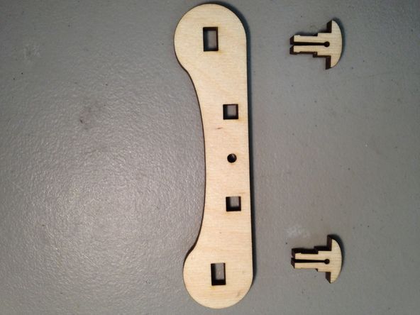
BJD dolls are printed as separate parts on a 3D printer, which are assembled on an elastic band using special fasteners.
Due to their good detail, ball-jointed dolls are very often used as models in photo shoots to demonstrate various reduced items of clothing, accessories, shoes, etc. Ball-jointed dolls are also popular for visual demonstration of various sports stances, yoga poses and other demonstration purposes.
What do 3D printed articulated dolls look like?
The 3D printed dolls have highly detailed facial features, body curves and even fingers. With proper refinement with the help of decorative materials, they will look very similar to people.
Thanks to 3D modeling it is possible to develop dolls with characteristic individual features (special eye cuts, different hand poses and different body parameters). In this case, they will be perfectly symmetrical.
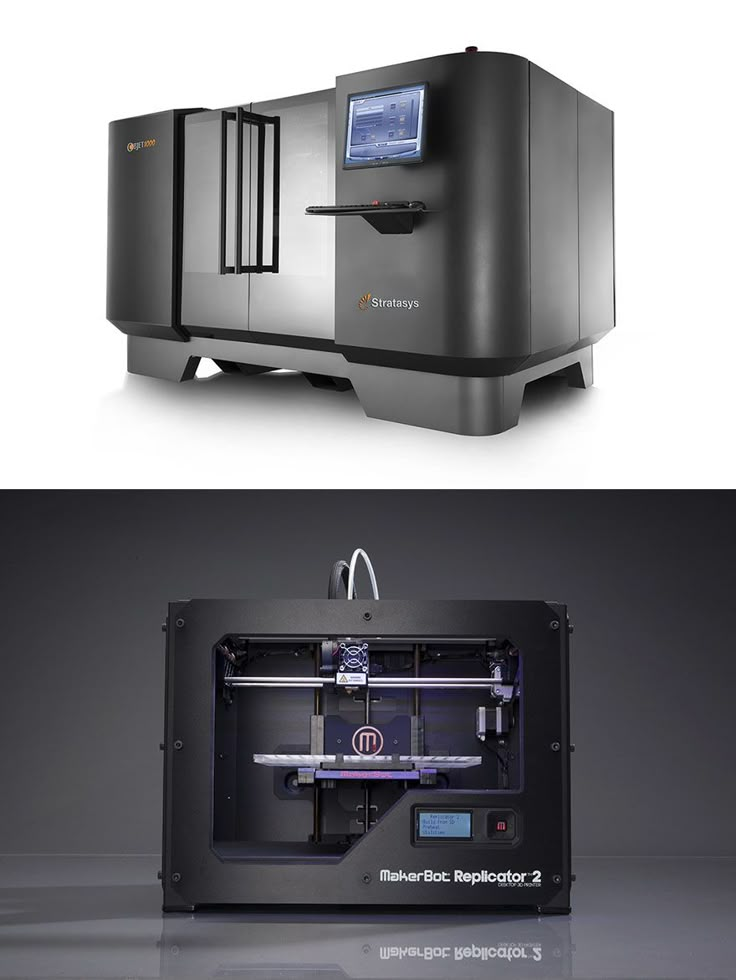
BJD dolls have a solid construction thanks to the material they are printed from (ABS plastic or translucent plastic (ProJet, Objet)).
Where can I get a 3D model?
Creating a 3D model of a ball-jointed doll is a very complex process that consists of designing each individual part of the product and creating supports. Therefore, few masters share their many hours of the fruits of labor.
But you can still find 3D doll models online. The largest number of files with different print formats can be found on two sites: https://www.thingiverse.com and https://open3dmodel.com. The first site is completely in English, but its database of 3D objects is quite extensive. The second web resource has a smaller number of models, but its localization is completely Russian.
How to print?
Creation of a ball-jointed doll on a 3D printer is carried out in seven stages:
- Development of a 3D model in a specialized program.
 Almost any software that usually comes with the printer is suitable for this. You can also use highly specialized programs for 3D modeling. You can skip the first stage of creating a doll if the user already has a ready-made three-dimensional model.
 Important! Jointed doll mainly consists of hollow parts. Therefore, before completing the development of a three-dimensional object, it is necessary to install support structures in the necessary places of the part, which will help to print the parts of the workpiece located in the empty space.
- Cutting finished product parts in a slicer. Each part must be cut into identical slices. Thanks to this, layer-by-layer printing will be more clear and will produce better quality blanks.
- Media selection. There are two recommended materials for making a ball-jointed doll:
- ABS plastic is durable and inexpensive. However, it has a low level of detail and requires post-processing (priming and sanding) after printing.
- Translucent plastic (ProJet, Objet) is a strong but expensive filament. It reproduces the fine details of the product well when printed. The surface is very smooth and does not require additional processing.
- Doll print. Sliced 3D doll parts are printed separately. Further, depending on the material used, the workpieces are cooled, washed in acetone or illuminated. After that, the supporting structures are removed.
- Post-processing parts. Additional surface treatment may be required depending on the material used. Most often they are sanded, sanded and primed. All these actions are necessary in order to remove the irregularities that have arisen during printing and remove the remnants of the supporting structures. After the part is painted in the main shade (flesh or any other, depending on the master's idea).
- Assembly of the doll. All prepared parts are assembled into a single product using special hooks or thick paper clips.
 When assembling movable dolls, high-strength elastic threads are used, which are stretched.
 - Decoration. At this stage, eyes, lips, nails and various small details of the product are drawn. Hair is also attached, clothes, shoes are put on and accessories are added.
The main advantage when creating articulated three-dimensional dolls is their realism. Dolls really turn out very similar to real people. It follows from this that a doll printed on a 3D printer can always look different. Thanks to 3D modeling, individual parts of the product are extremely detailed and can be designed in any way. Therefore, the master can create individual models of dolls that will fully meet the requirements of the customer.
Along with significant advantages, articulated dolls have a number of disadvantages:
- a very long process of creating a 3D model in a specialized program;
- Limited media available for printing;
- 3D printed dolls always need post-processing.

Creating BJD dolls on a 3D printer is a rather laborious process that will require certain modeling skills in specialized programs, good knowledge of working with a printer, as well as the ability to do post-processing and product design. However, if all these skills are present, then the user can easily create original gifts or sell unique dolls at a high price.
- March 22, 2021
- 9879
Get expert advice
Toy Story: How to 3D print life-like bjds | Prototypster
According to Natalya Bragina, when she first started making articulated dolls, there was no thought of using 3D printing. The artist became interested in dolls after visiting Disneyland Paris. The Rapunzel doll bought there evoked childhood memories and inspired me to create my own dolls. To date, Natalia has already made more than 20 different dolls. Of these, 4 dolls were made in Prototypster using 3D printing.
Beautiful Alyonka. 45 cm tall, polyamide, designer eyes, airbrush and brush painting (acrylic), handmade French tatting lace, mohair hair.
Natalya is an architect by profession. She is convinced that what tool (computer or pencil) a person uses when creating a doll is completely unimportant. « If there is no idea, soul, then the most modern technology will not help to create it. Ideas are born in my head all the time, I don’t have time to implement them ,” says the artist.
Maybe that's why Natalya Bragina's dolls turn out so natural, humane, each with its own character.
And green-eyed Alyonka again!
Articulated doll easily changes positions, almost like a person.
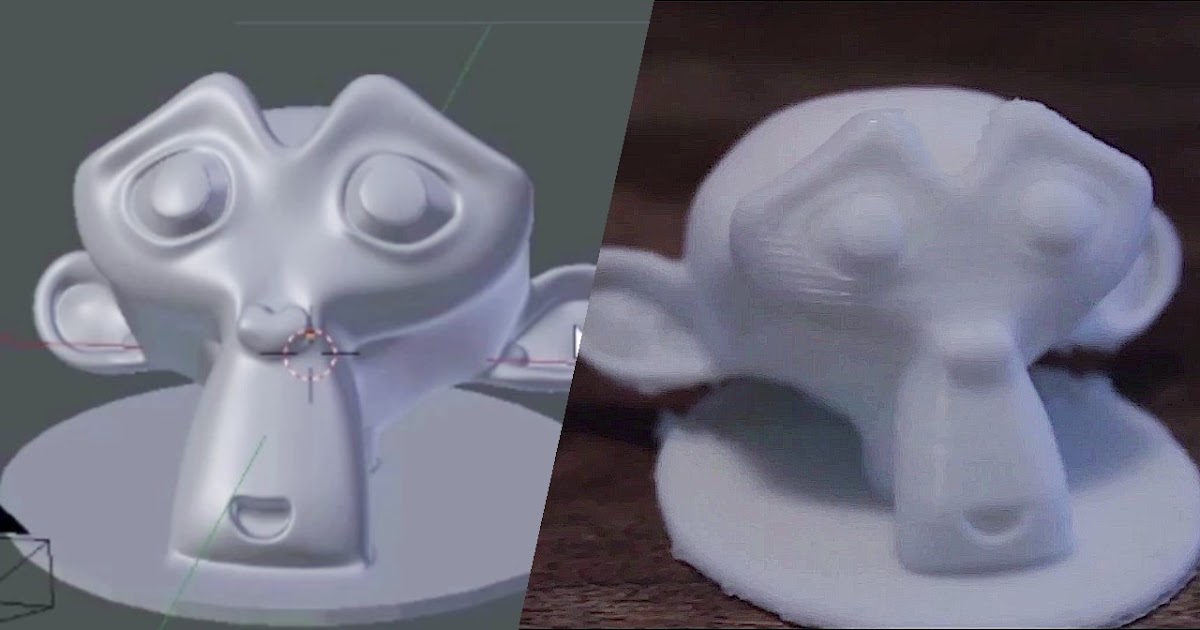
When we take doll parts out of the 3D printer container at Prototypster, we can hardly imagine the finished image. Thanks to 3D printing, facial features, the curves of fingers are visible in great detail, but it is the artist who can breathe life into them.
Dark Wizard. The doll can also become the embodiment of male beauty. 48 cm tall, polyamide.
Pensive dark magician.
Knight of the sad image.
Everyone can try their hand at making ball-jointed dolls, if you just want to. For example, to get started with 3D modeling. Natalya also started gradually, she made the first 3D model of the doll within six months. With experience, everything began to turn out faster. Now modeling a new character takes the artist from two weeks to a month.
When 3D modeling dolls for 3D printing, an error must be taken into account. According to Natalia, “ 3D printing is a very delicate technology. It's easy to get into trouble if you do not take into account that the hinge or eye socket can become a little smaller, and the hinge or eyeball can be larger than .