3D printer compatible with autodesk inventor
Using Inventor for 3D Printing | Search
View Original X
Products and versions covered
Inventor Products, Factory Design Suite, Plant Design Suite, & Product Design Suite
Ronald Jones, Sr. Solutions Engineer
Ronald Jones
Sr. Solutions Engineer
94 contributions
- 98 posts
- 68 kudos
- 9 solutions
- 6 ideas
REPORT
Report this article?
CANCEL REPORT
Inventor and 3D Printing
3D printing is quickly becoming the standard for prototyping. It’s cheaper, faster, a heck of a lot easier then manufacturing a part, just to find out that hold needs to be 5 thou bigger. Trust me we’ve all been there. Remembering back to the old days of Inventor, trying to create a 3D print of your model was difficult. There was file exporting, waiting, and sometimes even some profanities. The tides have changes though, with advancements in additive manufacturing and 3D printing Autodesk has included a tool in Inventor that allow us to quickly generate the mesh file we need for our 3D printers, and even send a file directly to the printer for use.
Where’s the Tool At?
I’m referring to the 3D Print tool inside of Inventor. Not the American rock band. This tool is easy to find, navigating to the Environments panel we are greeted by an image of a 3D printer towards the middle of the page. Clicking on this tool launches a representation of a print bed. This tool is designed to work natively with an Autodesk Ember printer, or a number of other 3D printers. From this environment, we can now set the orientation of our part, do some direct modeling if say we need to make it a bit longer, or even insert work planes. This is where it really gets cool, users have the ability to send this part over to Autodesk Print Studio or even Meshmixer. Users also have the ability to send this print directly to their printer. Utilizing the Print Options tool, you can refine your mesh structure, units, and even color.
Prototyping Out of Plastic?
With 3D printers becoming more and more affordable and cramming more technology into a smaller price tag, this new way of thinking almost sells itself. Thinking back to my days in industry our department literally had an entire area dedicated to machines we needed to machine and manufacture prototypes. These lathes, mills, and saws could be replaced with one 3D printer that takes up a heck of a lot less space and time. Prototype creation can take hours of your time cutting chips on a mill. Where as 3D printing only takes a few minutes and hitting the “Go” button. Errors can be caught earlier and normally cost less to revise, seeing as you only have a plastic part and not a full blown metal prototype. 3D printing is the future of making things, and Autodesk Inventor is at the forefront of this technology.
How can I use it for Non Native Inventor Files?
Utilizing Autodesk's AnyCAD technology that is housed inside of Inventor, users can use non-native Inventor files to create 3D prints. AnyCAD can open Solidworks, Creo, Catia, Solidedge, and NX files natively. Opening a Catia file for example for launch the AnyCAD menu, Converting the file into an Inventor part will complete the interaction with AnyCAD. From here users can use the same 3D printing tools described above. Users could even import a 2D DWG into Inventor, complete an extrude or revolution command to make it 3D then print it using the 3D print Enviroment in Inventor.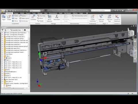 This means that a file can be created in any number of CAD packages then translated and printed using Autodesk Inventor. For more information on AnyCAD please visit: http://blog.advancedsolutions.com/topic/manufacturing/inventor-2018-part-2
Summary
Manufacturing and design is quickly evolving and changing, prototypes that use to be made out of metal and machined on a lathe or mill, are now being printed in a few hours and for a fraction of the cost of their metal ancestors. Using Inventor for 3D printing allows users to design a protype in canvas from Inventor, eliminating the need for 3rd party programs and exporting Inventor files to any number of "generic" CAD formats. Another benefit of this, is the ability to make changes quickily.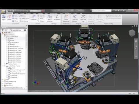 Because everything is inside of Inventor a quick change to the part doesn't warrant exporting and transferring to another program. This saves valuable time allowing the user to create a new 3D print with just a few clicks. The Future of Making Things is evolving rapidly, Inventor gives the flexibility to stay ahead of the curve.
{{l10n_strings.ADD_DETAILS_PROMPT}}
{{l10n_strings.SELECT_A_COLLECTION}}
{{l10n_strings.ITEM_ALREADY_EXISTS}} {{l10n_strings.ITEM_MAX_REACHED}}
{{l10n_strings.CREATE_NEW_COLLECTION}}
(* {{l10n_strings.REQUIRED_FIELD}})
{{l10n_strings.CREATE_NEW_COLLECTION}}*
0 / 80
{{l10n_strings.ADD_COLLECTION_DESCRIPTION}}
{{l10n_strings.COLLECTION_DESCRIPTION}} {{addToCollection.description.length}}/500
{{l10n_strings. TAGS}}
{{l10n_strings.PRODUCTS}}
{{$item.Name}}{{l10n_strings.DRAG_TEXT}}
{{l10n_strings.DRAG_TEXT_HELP}}
{{l10n_strings.COLLECTION_CATEGORIES}}
{{l10n_strings.GETTING_STARTED}} {{l10n_strings.LEARN_EXPLORE}} {{l10n_strings.TROUBLESHOOTING}}
{{l10n_strings.LANGUAGE}}
{{$select.selected.display}}{{article.content_lang.display}}
{{l10n_strings.AUTHOR}}
{{l10n_strings. AUTHOR_TOOLTIP_TEXT}}
{{l10n_strings.CREATE_A_COLLECTION_ERROR}}
{{l10n_strings.CONTRIBUTION_ADDED_TO_COLLECTION}} {{addToCollection.collectionTitle}}.
How to Prepare STL Files | Stratasys Direct
How to Prepare STL files
STL is the standard file type used by most additive manufacturing systems. STL is a triangulated representation of a 3D CAD model. Below you will find instructions on how to convert CAD to STL for many popular platforms.
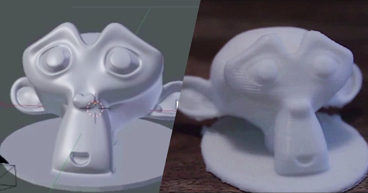
The triangulation (or poly count) of a surface will cause faceting of the 3D model. The parameters used for outputting a STL will affect how much faceting occurs (Figures 2 and 3). You cannot build the model smoother than the STL file. If the STL is coarse and faceted the physical 3D printed model will be coarse and faceted as well. However, the smoother/ less faceted your surface is, (the higher the poly count or triangulation) the larger your file. 3D printing can only accept a certain file size; therefore it’s important to find a balance between your model, its desired surface, and the 3D printing process of your choice.
An example of course triangulation.
An example of fine triangulation.
Your other option is to skip the process below as we offer instant quoting using just your native CAD file.
Simply sign-in, upload your CAD file(s), make your desired selections, click order, and get parts as fast as 2 days!
Yes, it is that easy.
Upload Native CAD here
When exporting to STL in your CAD package, you may see parameters for chord height, deviation, angle tolerance, poly count, or something similar. These are the parameters that affect the faceting of the STL. We’ve compiled tips on exporting for the best “surface: file” size ratio below.
Preparing your files
The following step-by-step instructions for converting CAD files to STL came from each CAD software company’s website or from 3D printing and design user forums; it’s an overall simplified step-by-step process from the greater 3D printing community. If your CAD software is not listed below or if you require additional assistance, please contact your CAD software technical support for information about exporting to an STL.
The CAD softwares covered below:
3D Modeling for Beginners
- Tinkercad
- SketchUp
3D Modeling for Engineers
- Autodesk Inventor
- CATIA
- IronCAD
- Rhinoceros
- PTC Creo Parametric
- Solid Edge
- SolidWorks
- NX
3D Modeling for Artists
- Blender
- ZBrush
- Maya
Don't have CAD software? SolidView is an affordable solution for non-CAD users to prepare STL files from many popular CAD formats. Start your free trial today.
Tinkercad
You can also just load your native CAD into our online quoting tool to get instant pricing!
Tinkercad is great for 3D printing simple geometrical objects. Its interface was created with 3D printing in mind.
- Design > Download for 3D Printing > .STL
SketchUp
You can also just load your native CAD into our online quoting tool to get instant pricing!
SketchUp does not offer STL creation directly within the program. Download the extension for .STL here (note: this plugin is open-source and updated frequently).
- Download and install the plugin
- Select Tools > Export to DXF or STL and select the units for your model (millimeters is recommended)
Tip: SketchUp isn’t inherently built for model production therefore it’s useful to check your SketchUp file for additional feature accuracies once it’s exported from the interface. We recommend uploading your SketchUp file into Meshmixer (a free program from Autodesk) to check your file for faceting and fix any surface flaws.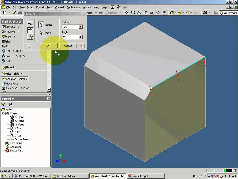
Note: We don’t recommend Sketchup for use with 3D printing as it does not export well and is best for early design sketches rather than producing physical models.
Autodesk Inventor
You can also just load your native CAD into our online quoting tool to get instant pricing!
-
-
- Select IPro > Print > 3D Print Preview
- Select Options and choose desired resolution and click OK
- Within the preview window, select Save Copy As or Send to 3D Print Service
- Save As type to STL File (*.stl)
-
Note: The “High” setting will also produce the largest file size. From Low, Medium to High, the hairdryer sample file in Inventor went from about 6.7MB to 17.6MB to 50MB.
Tip: Before finalizing your export, select the Options tab. Within this window, you can select the resolution (faceting) for your model (High, Medium, Low and Custom) and check that your units are correct. The “High” setting will produce a large file size.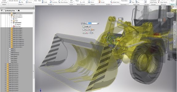 Autodesk Inventor allows you to save both individual parts and assemblies in STL format, at all design levels. For a quick overview of designing in Inventor, click here.
To check your modifiers have been applied before exporting:
- Tools > Rebuild All (this ensures that the design data contains recent changes, and that it is not corrupt)
- File > Save Copy As > STL (.stl)
- Select High and click OK
Note: To change the values associated with each of the resolution settings (High/Medium/Low) you need to edit the Windows registry.
CATIA
You can also just load your native CAD into our online quoting tool to get instant pricing!
- Select STL command (we recommend setting maximum segmentation to 0.015 mm)
- Select the model > Yes > Export
Note: CATIA V5 is capable of creating STL files from CATPart files, but not from assemblies (CATProduct files) or geometrical representations (car files). Therefore, source files, including those saved in a neutral format (i.e. STEP or IGES), must be saved as CATParts. If the source design was saved as an assembly, it is imported to CATIA as a CATProduct. To create an STL file from it, you must first convert it to a multi-bodied part. The procedure described below is one of several methods for doing this.
Saving CATProduct files as CATPart Files for 3D printing:
- File Menu > Open > select your source file (assemblies import as CATProduct)
- Save the imported CATProduct file
- Select File > New > Part > Name the new part
- Select one component from your master CATProduct File and copy it
- Paste the component in a new part window
- Repeat steps and until you have copied all of the components and pasted them as individual parts
- Once you have the assembly completely separate into individual components, select File > New Part
- Copy each of the individual components from the working files and paste them into the new combined model file (the geometries of all of the parts should retain and align correctly in the combined part)
- The new part is now ready to be exported as an STL file
- Select Tools > Generate CATPart from Product
- Finally, Select File > Salve As > Save as type: STL
Tip: Occasionally some of the components may not align correctly in the combined part because of the way the original assembly was designed.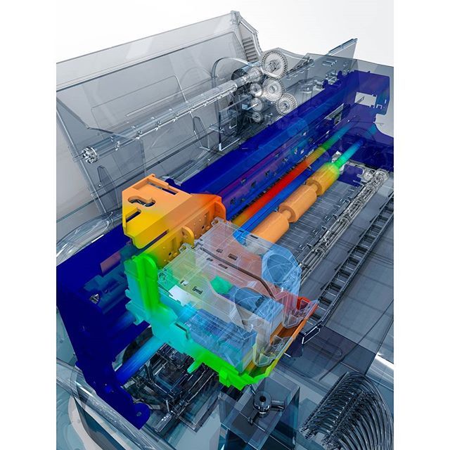 To align parts, select Insert Menu > Constraints Feature.
Before saving the file, it is advisable to review the settings that determine model accuracy and file size. To see these parameters:
- Tools > Options
- In the Options dialog box, display the Performance tab
- Under the General category (on the left), select Display
- Review 3D Accuracy settings
Tip: Curves’ accuracy ratio: The higher the setting, the smoother the surface will be when dealing with complex geometries, especially if surfaces contain sudden small changes with small radii (like the bumps on a golf ball).
IronCAD
You can also just load your native CAD into our online quoting tool to get instant pricing!
- Right-click on the part
- Click Part Properties > Rendering
- Set Facet Surface Smoothing to 150
- File > Export
- Select .STL
Note: IronCAD can export in many file formats depending on your geometry.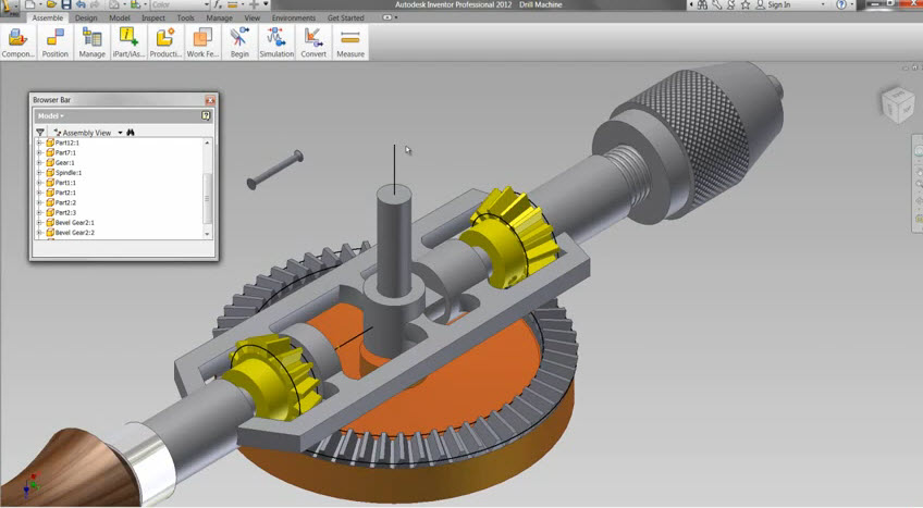
Tip: When working in assembly mode, you must save each of the component parts as individual STL files. The procedures for doing so are described below.
Saving a model design in STL format:
- Open the model design in IronCAD.
- Right-click on the part and select Part Properties > Part dialog box
- Make sure that the Rendering tab is displayed
- Change the Surface Smoothness setting to an appropriate value for your model.
- If you have not established an appropriate value, try 150. The higher the number, the smoother the model surface will be.
- Change the Max Edge Length setting to an appropriate value for your model.
- If you have not established an appropriate value, try 0.05. This setting produces good results, but increases file size and may require several minutes to render the model to STL format.
- To create smoother model surfaces when designing spherical and torus geometries, select the Triangulated Mesh check box.
 Selecting this check box results in larger STL files, but may produce smoother curves in models. If the surfaces of the model design are planes, this setting does not improve the results.
 - Click OK to save the settings and close the dialog box.
- File > Export > STL
- In the Stereolithography dialog box, make sure PC is selected, and select the Binary Output check box.
- Click OK to save the settings and create the STL file.
Rhinoceros
You can also just load your native CAD into our online quoting tool to get instant pricing!
- Select Object
- Mesh > From a NURBS Object
- Select Polygon Mesh > Detailed Controls
- Maximum aspect ratio: 2.0
- Perspective > Rendered View > Observe smoothness and confirm it meets standards
- To check that your mesh is uniform: Select the new object mesh > Analyze > Mass Properties > Volume
Rhinoceros 4
- File > Save As
- Select File Type as STL
- Select File Name > Save
- Select Binary
- Select Detail Controls from Mesh Options
- Max angle = 20, Max aspect ratio = 6, Min edge length = 0.
 0001
0001 - Click OK
Tip: Check your objects geometry and surface in the Object Properties tab to ensure object uniformity.
Rhinoceros Version 3 and Later
Rhinoceros enables extensive control of STL properties when saving designs as STL files. Because Rhinoceros software is surface-based, the complete model design (even if an assembly) is saved as a single STL part.
Saving a model design in STL format
- Select Part > File > Export Selected > In the Save As Type box, select Stereolithography (*.stl)
- Click Save
- In the STL Mesh Export Options dialog box, set the STL tolerance – the maximum distance allowed between the surface of the design and the polygon mesh of the STL file.
- If you do not know the other settings appropriate for your model design, try these:
- Tolerance: Less than half of the printer’s resolution. For example, the setting shown in the figures above (0.01 mm) is a good setting for printing models at a resolution of 0.
 03 mm
03 mm - Maximum Angle: Default
- Maximum Aspect Ratio: Default
- Maximum Edge Length: Clear
- Maximum Edge Length: Clear
- Maximum Initial Grid Quads: Default
- Refine Mesh: Check
- Pack Textures: Check
- Click OK
- In the STL Export Options dialog box, set the file type as Binary and click OK
- Note: If the Export open objects check box is selected, STL files will be created for each of the objects currently open. If this check box is cleared, an STL file is created for the selected object.
- In the STL Export Options dialog box, set the file type as Binary and click OK
- Tolerance: Less than half of the printer’s resolution. For example, the setting shown in the figures above (0.01 mm) is a good setting for printing models at a resolution of 0.
- If you do not know the other settings appropriate for your model design, try these:
Important: STL files are suitable for 3D printing if the models they describe are “watertight”, that is, they do not contain holes or gaps. If an error message appears, click Cancel and fix the model design before saving it as an STL file. Steps for fixing mesh in Rhinoceros are detailed below.
Troubleshooting Model Designs
If a model design contains holes or gaps, it is not suitable for 3D printing. Before saving it as an STL file, you must make it “watertight.”
To close holes and gaps in a model design:
- Check your object for errors: Command = Checknewobjects
- Surface errors will display
- Delete problem surfaces: Command = Selbad
- Command: Rebuildedges
Analyze Naked Edges:
- Analysis > Show Edges/ Edges Off > Command = Showedges
- Select object > Enter
- Within dialogue box, select Naked Edges
- Highlighted lines are naked edges and must be joined to the rest of your model
Fix Naked Edges
Option 1:
- Command = _Mesh
- This will create a mesh from the NURBS geometry (save your original NURBS file before doing this)
- Command = _Showedges
- This will detect naked edges
- Command = Fillhole
- If you cannot find the Fillhole command, open your Tools tab and select Toolbar Layout
- From the menu, check the box for Bonus Tools
- The Bonus Tools window will open
- Select Fill Mesh Hole
- If you have trouble, make sure you have the right updates installed
Option 2:
- Click the Mesh from Surface/ Polysurface icon from toolbar
- Polygon Mesh dialogue box will open
- Click Detailed Control > Polygon Mesh Detailed Options dialogue box will open
- Enter desired settings > OK
- Select entire object
- Tools menu > Polygon Mesh > Weld
- Command = 180 for angle tolerance
- The Weld command will merge adjacent triangle points when 180 angle tolerance is set
- Validate the object is watertight
- Command = SelNakedMeshEdgePt
- If the resulting object contains holes or gaps, the mesh needs fixed
- Repeat the Save As procedure
PTC Creo
You can also just load your native CAD into our online quoting tool to get instant pricing!
3D printing in PolyJet:
- File > Print > 3D Print
- Define Material
- Define STL resolution
- Tip: Check your file for printability through the Printability Validation Tab
Retired PTC Creo Formats: Pro/ENGINEER
- File > Export > Model
- Set type to STL
- Set chord height to 0.
 The field will be replaced by minimum acceptable value
 - Set Angle Control to 1
- Click OK
Exporting your STL file can be done at all levels of design, for both individual parts and assemblies. When dealing with assemblies, you can specify parts of an assembly to either include or exclude from the resulting STL file. Use the procedure below for saving both parts and assemblies as STL files for eventual 3D printing.
To save a Pro/E as an STL file:
- Check that the model design is continuous and “watertight”
- This step is especially important if the design was imported from a neutral design format because non-continuous bodies are likely to result in defective models
- To check for continuity:
- View the model with hidden lines displayed.
- From the View menu, select Display Setting > Scheme > PreWildfire. The model surfaces are displayed in magenta. If the design is continuous, the contour lines are white. If there are gaps, the lines are yellow.
- Fix the model design, if necessary, before saving it as an STL file.
- From the File menu, select Save a Copy. The Save a Copy dialog box appears.
- From the Type pull-down menu, select STL
Deviation Control
The Deviation Control settings in the Export STL dialog box affect the accuracy of the model and the size of its file.
- Open Chord Height (chordal tolerance)
- This setting specifies the maximum distance between the surface of the original design and the tessellated surface of the STL triangle (the chord)
- Chord height controls the degree of tessellation of the model surface
- The smaller the chord height, the less deviation from the actual part surface (but the bigger the file)
Angle Control
This setting regulates how much additional tessellation occurs along surfaces with small radii. The smaller the radii, the more triangles are used. The setting can be between 0 and 1. Unless a higher setting is necessary, to achieve smoother surfaces, 0 is recommended.
Once you have reviewed the above the controls and adjusted your settings, click Apply > OK to create the STL file.
Saving a Pro/E Assembly as an STL File
- File > Save a Copy
- From the Type pull-down menu, select STL.
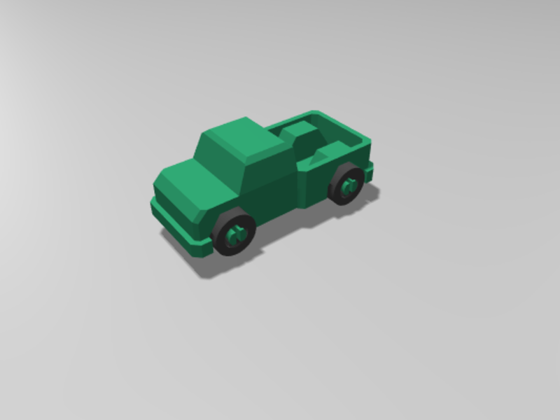
- Export STL dialog box appears: Specify the parts of the assembly to either include or exclude within the resulting STL file
- Example: In the dialog box one of the parts of the assembly (the tire) has been excluded, leaving two parts (the hub and the main wheel) to be exported to the STL file. The design resulting from these settings (when you click OK) is shown on the left.
- When you have made all of the required settings, click Apply and OK to create the STL file.
Solid Edge ST6 - ST8
You can also just load your native CAD into our online quoting tool to get instant pricing!
- Application Button > Save As (opens dialog box)
- From the Save As drop down menu, select STL documents (*.
 stl)
stl) - Select the Options button from the Save As dialog box
- Adjust Conversion Tolerance and Tolerance Units (millimeters recommended)
- The lower the conversation tolerance, the finer the tessellation
- Adjust the Surface Plane Angle (dependent your desired surface smoothness)
- The lower the surface plane angle, the greater the accuracy (noticeable in small details)
- As a rule, the finer the tessellation and the greater the accuracy, the larger the size of the STL file, and the longer it takes to generate it
- The lower the surface plane angle, the greater the accuracy (noticeable in small details)
- Under Output File as: Check Binary
- Binary STL files are much smaller than STL files saved in ASCII format
- Click OK > Save
Tip: Review the controls for exporting STL files in Solid Edge here.
Note: Solid Edge is capable of creating individual STL files from the components of an assembly, but this functionality is not built into the program. It is achieved through the application programming interface (API), using Visual Basic scripts.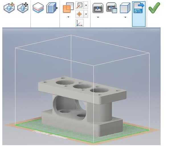 This solution does not enable a visual preview of the polygon mesh before saving the STL files.
Solid Edge (Older than ST6)
- Open model and select File > Save As
- Save As Type >STL
- Options > Conversion Tolerance: 0.0254 mm for FDM; 0.015 mm for PolyJet
- Set Surface Plane Angle to 45°
- Select Binary type and OK
- Name and Save STL file
Note: Solid Edge software from Siemens PLM (formerly USG) supports STL output at the core level, enabling you to save both parts and assemblies as STL files. However, when saving an assembly, all of its components are included in a single STL file.
SolidWorks
You can also just load your native CAD into our online quoting tool to get instant pricing!
- File > Save As
- Set Save As Type to STL
- Options > Resolution > Fine > OK > Save
STL settings: How to change STL settings
- File > Save As
- STL > Options
- For a smoother STL file, change the Resolution to Custom
- Change the deviation to 0.
 01 mm
01 mm - Change the angle to 5 (smaller deviations and angles will produce a smoother file, but the file size will get larger)
Tip: Review file export options before you save your file from SolidWorks here.
To save a model or a model assembly in STL Format:
- File > Save As (Save As dialog box opens)
- From the Save as type drop-down menu select STL (*.stl)
- Click Options
- The Export Options dialog box will display the file in a tessellated view
- File Format selection is STL
- In the Export Options dialog box > Output As section select Binary
- The resulting file size will be much smaller than a file saved in ASCII format
- In the Resolution section, select the appropriate option
- If you select Custom, you can manually adjust the Deviation and Angle settings
- The Deviation and Angle settings affect the tessellation of non-planar surfaces as follows:
- Lower deviation settings result in finer tessellation
- Lower angle settings result in greater accuracy, noticeable in small details
- Note: The higher the resolution, the larger the size of the file, and the longer it takes to generate
- For single material builds make sure that the following check box is selected: Save all components of an assembly in a single file
- This ensures that all components are saved as a single STL file.
- This ensures that all components are saved as a single STL file.
- For dual material builds (PolyJet) make sure that the following check box is NOT selected: Save all components of an assembly in a single file
- Note: Keep in mind that an assembly with many units will create many individual STL files when the “Save all components of an assembly in a single file” check box is left unchecked
- Click OK
- In the Save As dialog box, click Save
- In the confirmation message, click Yes
NX (Formerly UGS NX)
You can also just load your native CAD into our online quoting tool to get instant pricing!
NX software from Siemens PLM (formerly USG), supports STL output at the core level, enabling you to save not only entire parts as STL files, but also selected surfaces of a part. This gives you great flexibility when preparing objects for 3D printing. In addition, assembly output enables you to save several components as a single unit while maintaining each component as a separate volume (shell).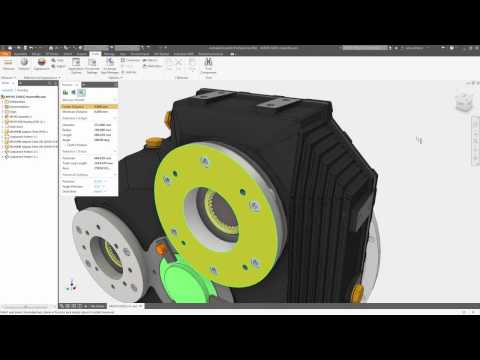
- File > Export > STL
- Rapid Prototyping dialogue box will appear
- Output Type: Binary
- Binary STL files are much smaller than STL files saved in ASCII format
- Triangle Tolerance: 0.015 mm
- This is the maximum distance allowed between the surface of the original design and the tessellated surface of the STL triangle, and affects the smoothness of the model surface
- Adjacency Tolerance: 0.015 mm
- This determines if two adjacent surfaces “attach”. If the distance between the two surfaces is less than this setting, they are considered attached. This setting must be less than the printing resolution. For example, when printing models at a resolution of 30 micrometers (microns), the setting must be no more than 0.03 mm.
- Auto Normal Gen: Check box
- Normal Display: Check box
- Triangle Display: Check box
- Click OK
- Export Rapid Prototyping dialogue box will appear
- Name your file and click OK
Blender
You can also just load your native CAD into our online quoting tool to get instant pricing!
Prior to exporting, ensure your object is uniform by checking that all surfaces/ vertices are connected.
To check your file for uniformity:
- Enter Edit Mode, select your object, and press “L” over the mesh
- Areas that do not highlight are free-floating. All vertices must be connected for your part to print.
- After you’ve confirmed your object is uniform, check for holes in the mesh of your part
- Enter Edit Mode, deselect all vertices, and select Non Manifold from the drop down menu or simply hit Shft-Ctrl-Alt-M
- Change the units and dimensions of your object
- Blender’s default measurement is called a Blender Unit and is equal to one meter
- Press “N” to bring up your dimensions tab
- Change units from Blender Units to Metric by selecting Properties > Scene Tab
- Change units to Metric (preferably millimeter)
- Adjust your scale within the dimensions tab to compute with Metrics
Now your file is ready for export.
- Select File > Export as .STL (* .stl)
Tip: Modifiers can be applied during export or prior.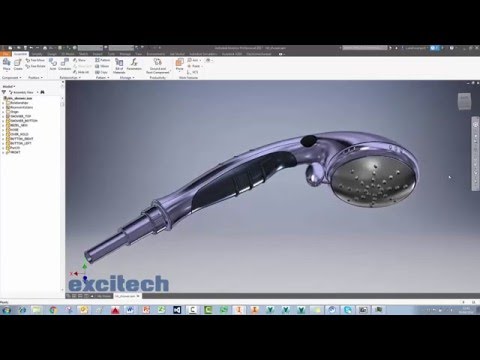
ZBrush
You can also just load your native CAD into our online quoting tool to get instant pricing!
ZBrush provides designers with incredible feature capabilities, however those features equate to thousands of tiny polygons that aren’t always feasible for 3D printing. To ensure your part is producible and that its details resolve as desired, download the Decimation Master Plugin from ZBrush.
The Decimation Master Plugin will allow you to optimize the polygon mesh of your part for printing by specifying a percentage of the poly mesh to preserve for export. It will preserve detail while reducing poly count. For a quick overview of the plugin, including masking to preserve areas where high poly count is critical for your model, click here.
Once you have optimized your part using the above steps, it is ready to export as an STL file.
- Download the 3D Print Exporter Plugin from ZBrush
- Select the ZPlugin menu
- Click 3D Print Exporter
- Define and scale your dimensions
- Select STL > STL Export
- Save
Maya
You can also just load your native CAD into our online quoting tool to get instant pricing!
Maya is a free-form design space not specifically tailored to production, therefore it is especially crucial to check the dimensions and producibility of your design (are the wall thicknesses defined? Are all vertices connected?).
Check features for producibility:
- Window > Settings > Preferences >Settings
- Change measurement units to millimeters
- Review dimensions and scale within the Chanel Box
- Finally, open Create > Scene Assembly
- Access measurement tools to check all feature sizes and thicknesses
Once you’ve checked your part for producibility, open the Rebuild Surface Options and define the surface density of your part. This will determine the resolution of the final 3D print. Check the design guidelines of your preferred technology to ensure the 3D print process can handle your desired resolution. Design guidelines on each 3D printing technology can be found here.
Now you’re ready to export.
- Select File > Export Selection > Export as STL_DCE.
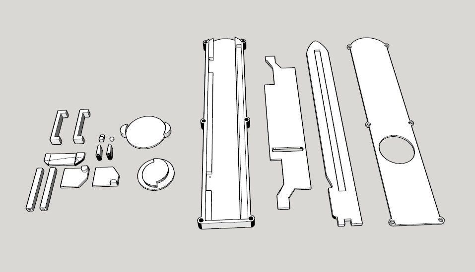
Overview of 3DPrintTech using Autodesk inventor as an example
3D modeling
The size of the parts is determined by the model of the 3D printer on which they will be printed.
 Also this plugin can be used to distribute multiple models on a large desktop. This plugin is compatible with AutoCad, Solid Works and Autodesk Inventor.
 Let's take a look at the plug-in functions using Autodesk Inventor as an example.
If the model was created in Autodesk Inventor, then open the model file.
Go to the Environments tab and click on the 3DPrintTech button.
Click on the 3Dprinter button and select the model and select the 3D printer model
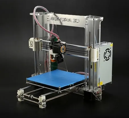
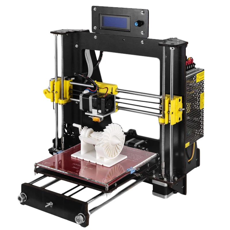
By default, in the plugin you will find such 3D printers as: PrusaI3, MakerBot Replicator, Up plus 2, Cube, etc.
If your 3D printer is not in the list, don't worry, just click on the Add new printer button.
In the window that appears, set the name and print area of the 3D printer, its image. For example, let's add Prism Uni and Prism Mini 3D printers.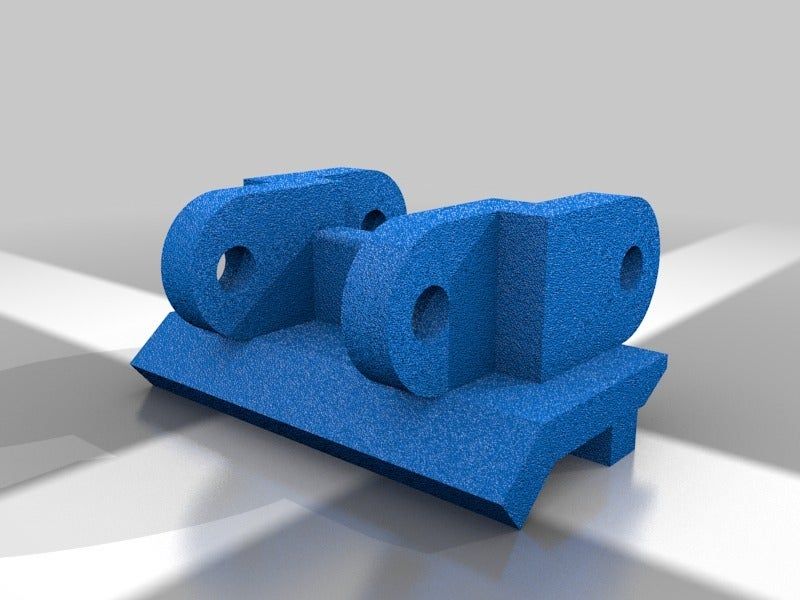 I draw your attention to the fact that the print area is set in inches.
After clicking on Save, the 3D printer will be added to the list and the next time the plug-in is launched, this action will not need to be repeated.
After choosing a 3D printer, you can start splitting the model by pressing the Split button.
Select the name of the model you want to split from the list. You will see a grid with the dimensions of the desired print area.
In this case, the model can be reduced or enlarged using the Scale slider (scaling).
Click next. On the next tab, you need to decide if you will create additional connectors between the parts. First, select the No option and do not create connectors.
Click on OK. After the command completes, you will see how the model is divided into the specified number of parts. At the same time, parts of the model are painted in different colors
To create an exploded view, click on the Explode button
In the window that appears, set the offset direction (in the example, the offset along all axes is selected) and its value.
The plug-in also has a Pack function that allows you to place all and several parts on a given print area.
Select the names of the models to be placed from the list.
Specify placement accuracy (Low-low, Medium-medium, High-high).
As a result, the models will be placed on the print area. Obviously, this feature should be used when you have several small models and want to place them on a large printable area. Although this feature is available in almost all slicers.
To save the resulting models, press the STL button
And select the name of the models that we want to save
Specify the folder to save
As a result, the selected models will be saved in the specified folder.
If you want to create connectors between parts, select Yes during the execution of the Split command. You can set the radius of the connectors, their length and taper. You can also edit the distance between connectors and their fill parameters. To avoid the intersection of connectors with each other or with the model, there is an option to check for intersections.
As a result, models are obtained as in the figure.
If you just have an STL model that you want to split, then create a part file. Run the plugin and select the required 3D printer. After that, the STL button will become active. We click on it.
Specify the units of measurement
As a result, the model will be imported into the plug-in and all operations described earlier will be available with it.
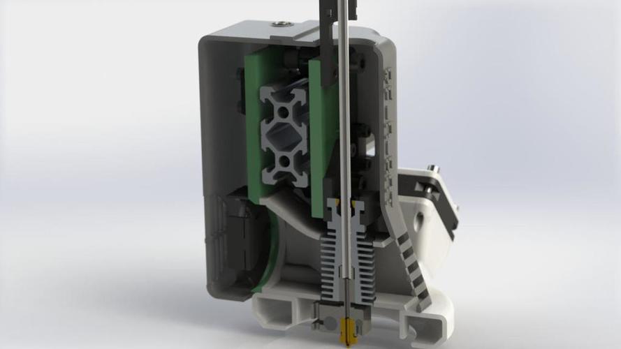
It is clear that all these “manipulations” are not needed if your 3D printer allows you to print a model in one go, like Prism Pro).
Follow author
Follow
Don't want
22
More interesting articles
terkum
Loading
11/12/2022
4155
51
Subscribe to the author
Subscribe
Don't want
Hello!
Not so long ago, about a year and a half ago, my grandson drew and printed...
Read more
19
Subscribe to the author
Subscribe
Don't want
At the beginning of September we released a new version of the KOMPAS-3D Home system for amateur 3D modeling...
Read more
arelav
Loading
03/13/2017
122134
111
Follow author
Follow
I don't want
Often when downloading this or that model we are faced with a situation that something does not suit it, or we want . ..
..
Read more
The best programs for 3D design technologies
-
What happens if you connect 7 RTX 4090 graphics cards? Performance and energy test (8 photos)
On its own, the GeForce RTX 4090 is a real beast, but PugetSystems went one step further and put together seven of these monsters in one PC and measured, among other things, the level of energy consumed by this installation.
Read more -
Any Google Pixel smartphone turned out to be easy to hack (video)
Google Pixel smartphones have discovered a major vulnerability that allows an attacker to unlock and gain access to the device.
Read more -
Laptops and PCs based on Chinese KaiXian processors were brought to Russia (3 photos)
In Russia, sales of laptops and mini-computers on the processors of the Chinese manufacturer KaiXian KX-6640MA with the pre-installed Russian operating system RedOS began.
Read more
-
Mediatek has announced a new flagship 4 nm processor - Dimensity 9200
The Dimensity 9200 processor is manufactured using a 4nm process technology at the Taiwanese TSMC factory. It is equipped with eight cores, while the ARM Immortalis G715 GPU with a built-in ray tracing processing unit is responsible for graphics tasks.
Read more -
The Chinese showed a rocket to fly to the moon
At the Chinese annual exhibition Airshow China 2022, a new generation superheavy launch vehicle developed as part of the national lunar program was demonstrated.
Read more
April 26, 2017 | ---
Vkontakte Odnoklassniki
It is impossible to set up production without drawings and technical documentation. Previously, hundreds of engineers worked on projects, but now it is enough to have a computer with a software package for 3D modeling and a few competent specialists. But the provision may be different. What rightfully deserves the title of the best?
3D Modeling and Design Software: Autodesk Leadership
Leadership in the field is firmly held by Autodesk. Almost all significant events in 3D modeling are related to the achievements of their creative development team. It is important that the company not only does not overprice its products, but since last year has significantly reduced the cost of licenses by switching to a subscription model of software implementation. Always up-to-date information about Autodesk products is offered by POINT on the pages of the portal https://www.pointcad.ru.
Today there are three noteworthy products in the Autodesk product line for designing simulation of various products: Inventor, 3ds Max, Fusion 360. Let's consider each of them in more detail.
Autodesk Inventor
Inventor is by far the best 3D design software on the market. She doesn't even need an introduction. However, the latest versions of the software package give even more opportunities for users:
- Automation.
 The main task of Autodesk is to transfer routine work to the computer, freeing up time for creativity. For this, various generators, process accelerators, libraries of ready-made components, etc. have been developed.
- Integration. Inventor is of course compatible with any Autodesk software. For example, it is easy to create a 3D model based on a 2D AutoCAD drawing. But that's not all - thanks to the unique AnyCAD technology, models from third-party CAD systems get associative links if they are opened in Inventor and make changes there.
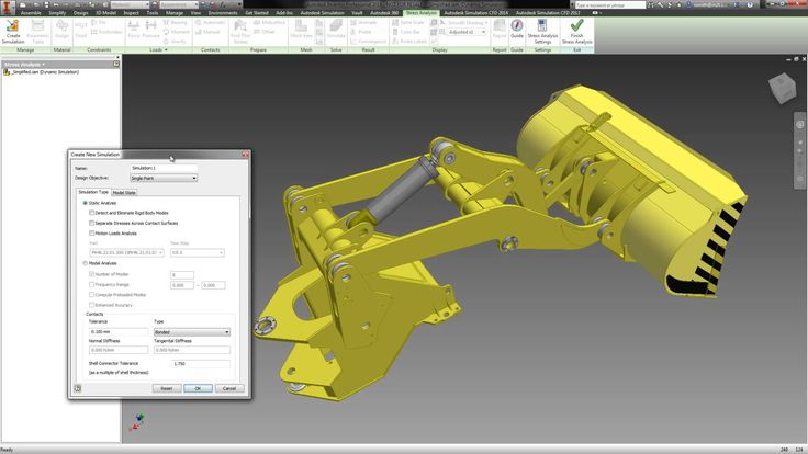
- Realistic. The system allows you to check the designed mechanism by simulating real load conditions or create an image that is difficult to distinguish from a photograph.
- Any difficulty. The Autodesk Inventor complex can handle even the most complex shapes and really large assemblies. Moreover, the requirements for the technical equipment of the computer are minimal.
In other words, Inventor is a professional 3D modeling tool. With its help, the largest production facilities around the world are launched.
Autodesk 3DS Max
3ds Max is another brainchild of Autodesk and a powerful visualization tool. The 3D modeling and design software has almost limitless applications:
- Animation and cinema. Modern animation projects are created using the 3ds Max environment.
- Computer games. To implement a major game project, it will be enough to have 3ds Max in the arsenal. And the matter concerns even the most complex 3D-forms.
- Architecture. A popular product among advanced architects who want to organize a spectacular presentation with animation.
- Industry. Show the process of work or assembly on the screen before the release of the real model.
- Interior design. 3ds Max allows you to see the interior even before the selection of materials and construction.
Companies partnering with Autodesk help you learn about all the product features. For example, on the page https://www.pointcad.ru/product#prod_3d there is a corresponding section with a description and functional characteristics. There is also a highly professional support service, so it is quite possible to understand all the intricacies.
Autodesk Fusion 360
Fusion 360 is the best 3D design software in the cloud. When it was created, the developers tried to make the design process even more convenient and comfortable. Fusion 360 combines the features of Inventor with the ability to work on the model at once by several specialists.
In addition to the obvious benefits of the cloud, Fusion 360 is self-contained software. It allows you to go through all the stages from an idea or sketch to production:
- Design (CAD). All the possibilities of modern 3D modeling are at your disposal: splines, solids, parametric modeling, mesh models, etc.
- Analysis (CAE). Multilateral engineering analysis of the future mechanism, assembly design, kinematic analysis, rendering, animation and other features.

Learn more