Lathe 3d printer
3D Printing CNC Lathe Part Catchers with Hugard and Markforged
On the production line, process automation is essential to control manufacturing output and guarantee a standard of efficiency. Hugard Inc. manufactures precision turned parts using CNC lathes, and a challenge they have always faced is how to collect parts as they’re parted off the lathe.
Ordinarily, an arm and grip would grab the turned parts or bundle them into a collection container, but because the parts are extremely complex and subject to a constant stream of corrosive-cutting fluid, they can’t be handled by plastic grips and they’re unsuitable for CNC milling. What Hugard Inc. have, then, are complex parts made by a CNC lathe that can’t be picked up by CNC fabricated grips. Talk about a double whammy.
Solving the challengeHugard Inc. solved the challenge with 3D printing. They used the Markforged Mark Two to fabricate a custom claw. The custom claw is made from Onyx and Carbon Fiber. It has a higher tensile strength than 6061 aluminium, excellent hardness, and supreme abrasion resistance. They use the custom claw as a parts collector; it catches turned parts as they’re parted off the CNC lathe. The process is completely automated and 100% efficient.
It’s important to point out that a claw fabricated from ABS wouldn’t function in the same way because it would have neither the strength or chemical resistance to withstand a cycle.
Using Markforged technology, Hugard Inc. prints claw grippers 16x cheaper and 25x faster than they can by CNC machining them. The alternative to 3D printing the grippers is CNC machining them from aluminium. This is a much more time-consuming task and the average cost per part is $400. With 3D printing, that cost is reduced to $25.06 per part. A 94% saving. The manufacturing time is slashed from 114 hours to 6-hours.
The CNC Part Catcher
It might look inconspicious, but this part is stronger than 6061 aluminium!
Continuous Carbon Fiber reinforcement material allows the catchment system to securely hold the part as it’s being parted off the lathe. The gripper is stronger than 6061 aluminium and can withstand hundreds of cycles. The unique properties of Onyx and Carbon Fiber mean the grippers can withstand cutting fluid, be it oil or water based. ABS and other thermoplastics would dissolve or degrade exposed to the same liquids and gels.
Crucially, the grippers would be nearly impossible to machine to the same standards. The thin walls and intricate features of the 3D printed grippers would take 144 hours to recreate with CNC machining.
With incredible performance and fabrication cost and time savings, Hugard Inc. have found a truly permanent solution to the challenge of collecting parts as they’re parted off the CNC lathe. If you enjoyed this case study, you can find more like it at our engineering and manufacturing page.
3D Printer: Mark Two (Enterprise).
Material used: Onyx, Carbon Fiber. The Markforged Mark Two can also 3D print Fibreglass and Kevlar.
This information was first published on the Markforged website.
Machining a 3D printer nozzle on a Mini Lathe — CNC Kitchen
Well, it finally happened, and I bought myself a Mini Lathe after desiring one for years. You ask why? Well, that’s also what my wife asked. As This Old Tony once said, you always need one more milling machine, and I think that also applies to lathes. Well, I regularly have projects in mind like for example special nozzles for the Filastruder that would require such a tool. I desired having a lathe at my disposal because this is, in my opinion, one of the most honest ways to machine metal. It’s such a pleasure to dive your tool into the material, adjust the pressure with your hand and just feel the metal being peeled off. Probably also one of the reasons why I’m currently not planning to convert it to CNC, or what do you think? I don’t have a lot of space and it had to go down into my basement, so a Mini Lathe, in my case the Sieg SC2 with a 500W motor and 400mm distance between the centers, was the machine of choice.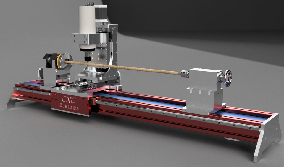
Paulimot Sieg SC2
I bought mine from a local vendor that also just imports them but I hoped for more quality control on their side. The lathe was around 1000€ delivered plus another 500€ for additional tools and accessories. You can get similar models cheaper, but this one at least came with all metal gears and a tailstock with a quick lock. Even though I didn’t do any real modifications, I still took it apart, cleaned all the ways put it back together and adjusted the gib strips. The only thing I really changed is adding a Multifix Tool Post, and that thing is a piece of beauty and worth every penny!
Multifix Toolpost
So I had it for a good two weeks and seriously enjoy using it. I’m not a trained machinist and the last time I was working on a lathe was 13 years ago. To learn using one of those machines again, I thought it might be interesting to try to machine a 3D printer nozzle, because it has a lot of features that are a bit challenging and a good way to learn, most notably the 0. 4mm hole in the front! I’ll be using the E3D V6 nozzle design but chose an older version of the drawing that doesn’t have the 60° taper on the inside because I don’t have a tool for it. I’d be interested to know from experienced machinists if that could be done by just grinding a drill bit to that tip angle. The older design uses a stepped bore which is not perfect for the flow, but will probably still give us 95% of the performance. I did a quick design from the original in Fusion 360 to create another drawing that had all the dimensions that were interesting for me and also important for machining, especially the depth of the bores measured to the tip of the drill bit.
E3D V6 nozzle drawing with machining dimensions and stepped bore
All right, so let’s get to the lathe! I’m using brass for the nozzle and to be more precise MS58 or a brass with 39% Zink and 3% Lead, which is probably the most common brass alloy and well suitable for this application due to its good thermal conductivity and machinability. Since I was lazy and wanted to save myself the step of later milling the flats, I directly purchased 7mm hex stock. Since it wasn’t that long, I didn’t bother cutting off a bit and directly put it into a 3-jaw chuck. I figured that I would need two setups for machining the nozzle. We’ll make the M6 thread and the inner bores in the first one and then turn everything around, and machine the tip, as well as the tiny nozzle bore.
Hex Stock in the 3-Yaw-Chuck
For the first operation, I’ll be using a 1.5mm wide, high-speed steel, parting tool to create the thread relief. I locked the carriage into place with the half nut lever while the feed rod was disengaged. I first faced the stock off to have a reference surface and zeroed the digital handwheel dial. Then I moved the tool the 7.5mm mark machined away the hex, zeroed the crossfeed handwheel dial, measured, machined away more, and checked the final dimension. With this high-speed steel parting tool, I have to go quite low in terms of RPM to get a good cutting result. The 7.5mm need to be pretty precise because they form the reference dimension for the second setup and if they are off, the length of our small 0.4mm bore might be off, causing non-optimal flow.
HSS parting tool
Next, we need to get the threaded section to size, and for that, I used a regular left-handed cutting tool with a carbide insert. Many claim that the Mini Lathe is not made for carbide tooling because carbide needs high cutting speeds and a stiff machine, but so far, it worked pretty well for me and didn’t require me to learn to grind my own tools from high-speed steel. I turned down the hex so that I was able to measure the part and then removed the rest of the material. I slightly de-burred the edge of the relief with this tool as well.
The 10 Tools used to machine the nozzle
Next, we use a square insert for machining the chamfers. I slightly touched the edge for zeroing and then machined a nice, big chamfer. I also added a small chamfer at the hex just for visuals.
For the threads, we have two options. The first and easy one that works with these small threads is using a regular thread cutting die and a tailstock die holder. This contraption provides you with an easy way to align the die with the workpiece. The holder is rotatable and free to move on its axis. You start the lathe at low RPM , hold the die in your hand until you reach the end of the thread, and then just let it go—perfect threads in a matter of seconds.
Thread Cutting with a Tailstock Die Holder
The more advanced, versatile, and in my opinion, also most satisfying way is to use a threading tool. Here, you lock the rotation of the chuck to the movement of the carriage by gears in the back that connect to the feed rod. By selecting the specific combination of gears, this results in 1mm of feed per rotation of the spindle, just as we need it for our M6 thread. So we engage the half-nut, slowly cut one pass, retract the tool a little and move it back in reverse. The first pass is a scratch pass on which I check the pitch with a pitch gauge, to make sure that I selected the right combination of gears. Cutting threads this way might be a tedious process, but I find it oddly satisfying. The deeper we get in the thread the more material the tool cuts. I only took shallow passes and used a spring pass from time to time and plenty of cutting oil. You could check the thread with special tools, but since I don’t have those and precision, in this case, isn’t crucial, I just use a nut as a gauge and go deeper and deeper until I could screw it on.
Thread Cutting Tool
The last operation of this first setup is drilling the deep holes. For this I put a drill chuck in the tailstock and started with a center drill, that is rigid and doesn’t wobble around and will create a pilot hole for the longer and more flexible drill bits. So the stepped hole needs to be reasonably precise. The tailstock has a scale on it, but that’s more for rough depth estimation. I didn’t know any better and made myself a makeshift DRO, by clamping a small, 3D printed part to the quill and using that as a stop for a dial gauge.
Makeshift DRO
To find the zero-depth, I used a thickness gauge between the drill bit and the part to measure where I was. First, I drilled the 1.5mm hole and regularly retracted the bit to clear it from the chips. The 2mm hole was way easier to machine because the amount of material that is removed was quite low. Since this operation is crucial for the interior surface finish, I still cleared the chips regularly because I wanted them to rub against the surface as little as possible, and I think this way, you don’t even need to ream the bore. In the end, I just added a small 60° chamfer with a chamfer bit, before I parted the nozzle blank off with around 2/10 of a mm extra in length.
Drilling the 2mm hole
Mounting the brass part on its threads in the three yaw chuck would ruin it, so I threaded a piece of aluminum rod, that’s then mounted in the chuck and in which I screw the nozzle blank. A collet chuck would have also been an option, but that would have required me to change it. I faced the part off and had to slightly readjust the tool height because it left a small bit of material where we soon want to drill with our tiny drill bit, for which we need a perfectly flat surface.
Nozzle Blank in Aluminum Holder
For machining the tip, I again used the square insert tool that we also used for the chamfers. The drawing asks for a 70° tip, but the standard orientation of the tool is 90°. I could rotate the whole compound, but that’s a pain on the Mini Lathe. Instead, I moved the toolholder just one set of teeth further on the MultiFix toolpost, which is 9° instead of the 10° required, but I guess good enough for our application. I zeroed the compound dial at the face and the cross slide roughly at the hex. I moved the tool 2mm in and then plunged into the hex to create the tip. This operation is something that this tiny lathe doesn’t really like, because at some point, a considerable portion of the tool is in touch with the workpiece creating huge cutting forces. Still, it made it with acceptable surface finish. Measuring the diameter of the tip is quite tricky, but I did my best to stay within the tolerances.
At last, we have to drill the orifice with the tiniest drill bit I’ve ever used. I made a pilot hole with the smallest center bit I could find but still had to pay attention that I only just slightly touch the tip because the center bit has a diameter of 0.5mm, which would result in a stepped tip and wouldn’t be optimal. For these drilling operations, I ran the machine at its maximum 2500 RPM to keep the cutting speeds high, but it would have been better to increase it even more. Next, I mounted the 0.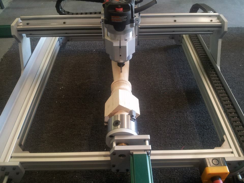 4mm drill bit in the drill chuck, made sure that the ways are clean so that the tailstock is centered, and just went for it. We have some slight wobble in the beginning but quickly start drilling. And there we have it, the finished nozzle! Doesn’t look too bad, does it? Performing the operations in this order left no burr in the nozzle orifice and left us with a nice and sharp corner.
Drilling the 0.4mm Nozzle Orifice
But the proof of the pudding is in the eating and I’ve therefore printed a test part with it and also cut one open to take a look on the internal surface finish. To dissect it, I put it into a collet block which I mounted in a vice on my CNC router and just machined half of the nozzle away in 0.5mm increments using a 6mm, three-flute carbide cutter.
So let’s take a closer look at it. Surface finish is not perfect, but I think very acceptable and way better as I’ve seen on other nozzles in the past. The depth of the internal bores were a bit too shallow, which leaves us with a nozzle bore that is a bit too long. Still, I think a very acceptable result for my skill level and the cheap machine I made it on.
Nozzle Tip
I machined several nozzles the last days, so let’s also test another one how it prints. I removed the genuine E3D nozzle on tool 2 of my E3D toolchanger and printed two 3DBenchys side-by-side. First, the one with a genuine E3D nozzle is finished, then the tools are changed and we print with my own, self-made nozzle. At first glance and even on closer inspection, there isn’t any significant difference besides the color visible, and I’d say, my nozzle didn’t perform any worse.
Printing 3DBenchys for Benchmarling on the E3D Toolchanger
If that’s due to my machining skill or because a 3D printer nozzle doesn’t need to be perfect is a question for another video. But what do you think about this project and what are your ideas and designs that you’d like to see tested in the future? Should I do more videos using the Mini Lathe? Let me know down in the comments!
Mini Lathe (aff): https://geni.us/OMvoY
Carbide toolset (10mm / 3/8") AMAZON (aff): https://geni.us/Qd0BD
Carbide toolset (10mm / 3/8") ALIEXPRESS (aff): https://geni.us/1qqmqZ
Multifix Tool Post Size Aa AMAZON (EU) (aff): https://geni.us/A7HA1l
Multifix Tool Post Size Aa ALIEXPRESS (aff): https://geni.us/BonNVcQ
Thread pitch gauge AMAZON (aff): https://geni.us/aECDES
Thread pitch gauge ALIEXPRESS (aff): https://geni.us/h0gNW
Mitutoyo Calipers AMAZON (aff): https://geni.us/yzlblI4
Mitutoyo Dial Gauge AMAZON (aff): https://geni.us/B4rCh
ER32 Collet Chuck ALIEXPRESS (aff): https://geni.us/Wvdz
ER32 Collet Block ALIEXPRESS (aff): https://geni.us/CodoS9m
ER32 Collet Set ALIEXPRES (aff): https://geni.us/viUg1
ER32 Collet Set AMAZON (aff): https://geni.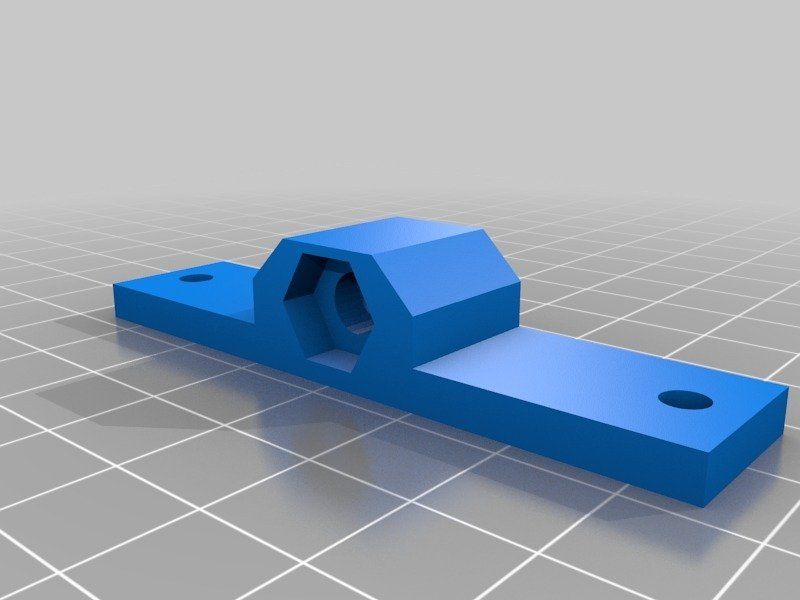 us/GUgWC
Stefan Hermann
0 Likeswhich is better for prototyping?
3D printing and CNC machining are more popular and affordable than ever. When you want to make a prototype, you decide what is best to use.
In this article, I will show you the strengths and weaknesses of each technology to help you make a decision.
Difference between 3D printing and CNC machining
The difference between 3D printing and CNC machining is that 3D printing is additive manufacturing while CNC is subtractive manufacturing. 3D printers have a nozzle that feeds layers of material to make parts, while CNC machining consists of a cutting tool that removes material to make parts.
CNC machines allow you to change the cutting tool according to the complexity of the application. As a result, CNC machines can be used to produce relatively more detailed products with high precision.
On the other hand, 3D printers are capable of creating complex shapes, making them ideal for rapid prototyping applications.
But is a 3D printer a CNC machine? Short answer: yes, it is a type of CNC machine that consists of a computer-controlled nozzle to print material.
However, 3D printing involves heating the working element, followed by cooling and solidification. This increases the total processing time required to manufacture the object.
In addition, there are many other differences that distinguish a 3D printer from a CNC machine.
Workflow
Looking at CNC machines and 3D printers from a technical point of view, both of these machines are controlled by a computer.
Interestingly, 3D printers belong to the CNC additive manufacturing industry.
3D printers are a type of CNC machines.The CNC motion control system is responsible for moving the cutting head over the material.
In 3D printers, the cutting head has been replaced by a print head that applies material and a controller controls its movement to print the desired shape or object.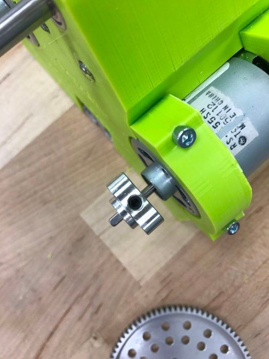
Like any other CNC machine, 3D printers also have a similar workflow. Differences arise in the production process.
A typical workflow for CNC machines and 3D printers includes:
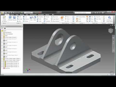
- Design part model in CAD software,
- Create toolpath for CAD design using CAM software
- Check program file for errors with simulation software
- Correct design or toolpath errors.
- Machining or printing a part.
CNC machines use CAD/CAM software to create designs and G-code files that are programmed into the machine for production.
Most 3D printing applications only require a 3D part design file to print. He then uses the CAM software to create a part program from the project.
The software used with 3D printers is similar to the CAM software used on CNC machines. They generate a G-code file used by CNC controllers.
Material Waste
CNC Metal Milling Material wastage in 3D printing is lower than in CNC machining.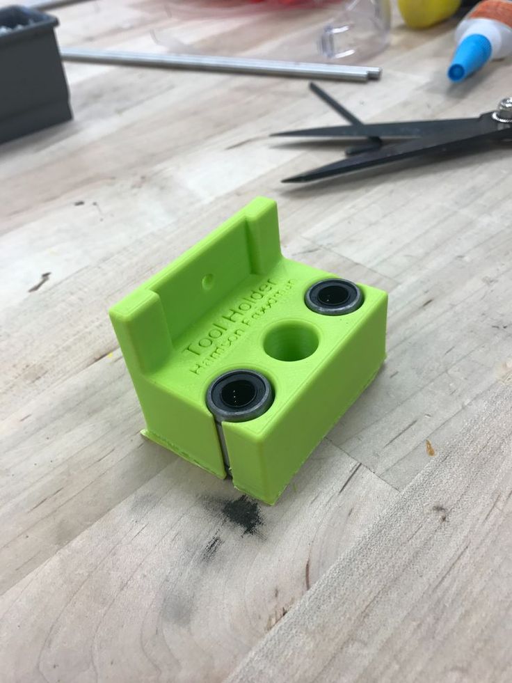 The main reason is that 3D printers only use the required material to create a part.
Because CNC machines use subtractive manufacturing techniques, they continuously cut out a block of material to give it the desired shape, resulting in a lot of material wastage.
Size and assembly
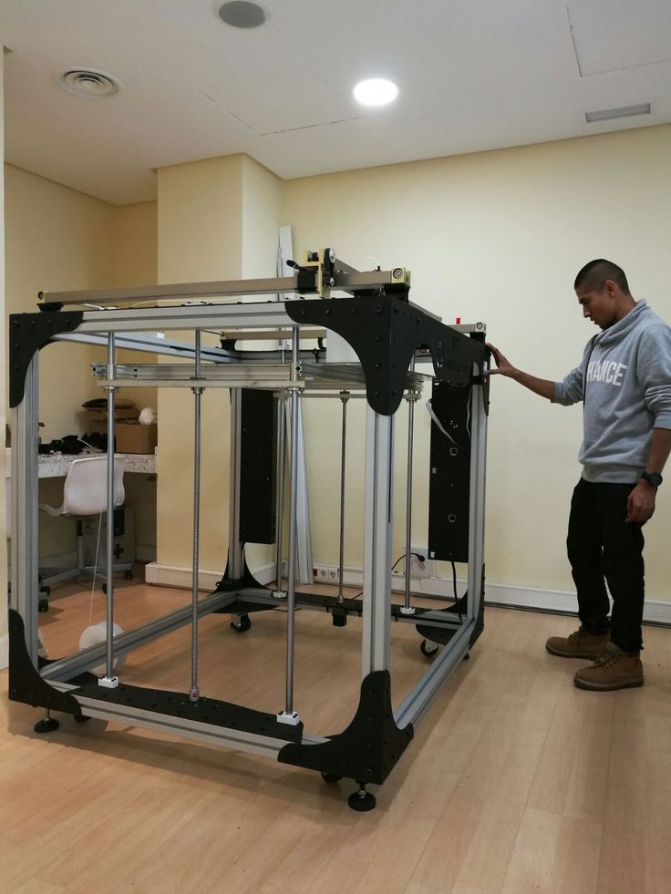
Compared to 3D printers, CNC machines are readily available in larger sizes. Making 3D printers more portable than CNC machines.
Most XXL rated CNCs have a footprint of a few square meters, while large 3D printers can have a maximum footprint of 1 square meter.
For example, some of the giant 3D printing machines have a build volume close to 1500×1200mm. While most industrial grade CNCs can have a working area of 3500 X 10,000 mm or more.
Since the CNC removes material from the workpiece by force, it must have a rigid construction strong enough to withstand high cutting forces.
The rigid frame is one of the most important parts of a CNC machine. This is the frame that holds all the other components together. It also acts as a guide for the cutting tool and provides a precise path for the tool.
On the other hand, 3D printers use the material in a molten or powder form, which eliminates the need for a rigid structure to apply high forces during the printing process.
Additions
CNC CoolantDuring machining, these machines use certain additives to provide a suitable processing environment for the tool and material.
For example, the CNC uses cutting fluids to lubricate and cool the point of contact between the material and the tool. Sometimes they also require dust collectors to keep their working environment clean.
In the case of 3D printers, they use a heated platform to help adhere the object to the print surface.
Tools
VMC threading CNCs are versatile machines that allow you to change cutting tools to perform different types of cuts with different sizes and finishes.
3D printers lack this flexibility, and the printed object has the same resolution with a constant layer thickness throughout the print.
Accuracy and reproducibility
CNC machines can achieve higher precision than 3D printers because of the way they work.
The rigid frame of the CNC machine provides high repeatability with minimal vibration, making it suitable for high volume production where multiple items with the same dimensional accuracy are required.
On the other hand, 3D printers melt and print material layer by layer, resulting in printed parts subject to slight dimensional inaccuracies.
Surface quality
3D printed plastic part (left) and CNC plastic part (right)In terms of surface quality, CNC is better than 3D printed. This is due to the wide range of tools used by the CNC.
With various tools such as ball end mill, end mill, grinding belt, etc., the CNC can produce workpieces with high surface quality.
The layering process of 3D printers leaves behind a rough surface texture on the workpiece.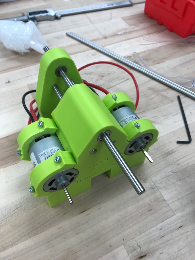
Today, 3D printed parts are treated with surface finishing methods such as painting, powder coating, electroplating, etc. to obtain a smooth surface.
Part strength and stability
Compared to 3D printing, CNC machining allows parts to be produced with tighter tolerances and greater strength.
CNC machines have a tolerance of ±0.025mm, while advanced 3D printing techniques such as direct metal laser sintering (DMLS) can only achieve a tolerance of around ±0.1mm.
In addition, because the CNC uses subtractive manufacturing techniques to make the part from a block of material, it does not lose the original strength of the material.
The 3D printer adds layers of material on top of each other that are fused together to form the final product. This reduces the overall strength of the part, making it prone to breakage.
The minimum line thickness that a modern 3D printer can achieve is 0.4 mm.
Costs
CNC machines are comparatively more expensive than a 3D printer with the same working area.
In addition, the need for various accessories such as coolant supply system, special cutting tools, etc., further increases the maintenance cost of CNC machines.
For small prototyping businesses, a 3D printer is a cost-effective option because it allows prototyping without the need for expensive equipment.
CNC and 3D printing - basics
Additive and subtractive manufacturing
Additive ManufacturingAdditive manufacturing is a technique that involves adding material layer by layer to produce a desired part or object. For example, 3D printers work on this principle.
This method is used for rapid prototyping of parts, production of complex parts and creation of customized products.
Subtractive ManufacturingThe subtractive manufacturing process removes material layer by layer from a blank block to create an object.
This is done with cutting tools and machines such as lathes, milling machines.
What is a CNC machine?
Various types of CNC machines A CNC machine is a computer-controlled tool that can be used for various processing operations such as cutting, shaping and shaping various materials.
These machines usually have three axes of motion and can produce complex shapes from materials such as metal, wood, plastic, etc.
CNC technology has been used in manufacturing for decades. This allows machines to be programmed to perform complex operations automatically.
It is now an integral part of the production process in many industries and can be found in various types of machines.
Some of the common CNC machines include CNC milling machines, CNC lathes, laser cutters, plasma cutters, electrical discharge machines (EDM), grinders, etc.
What is a 3D printer?
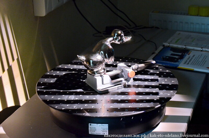
Vase 3D Printing with Snapmaker 2.03D printer is a type of automated machine that follows the principle of additive manufacturing and uses numerical control technology to produce the desired part from a CAD file.
These machines create 3D objects by laying down successive layers of material on a build plate until the object is complete.
The most common type of 3D printer is Fused Deposition Modeling (FDM) printers, which work by extruding thin filaments of heated plastic, metal, or other materials that cool and solidify after being deposited.
Practical application of 3D printing and CNC machining
Practical application of 3D printing and CNC machining depends on the material you plan to work with, the type of part you want to produce, the quantity and speed at which you want to make them.
The type of material you plan to use
The materials most commonly used for 3D printing are plastics, metals, and some biomaterials such as sugar or wood pulp.
3D printers can also use other materials such as ceramics and concrete, but these materials are less common because they take more time and effort to produce than plastics or metals.
By comparison, CNC machines can cut and mill almost any material. Some popular CNC machining materials are metals, wood, and plastics.
The materials that a CNC machine can cut depend on the design of the machine and the type of cutting tool installed in its cutting head.
Which is better for making metal parts?
CNC milling machine processes a metal workpiece. The
The CNC machine is best for making metal parts because its rigid structure and transmission provide higher precision and accuracy than a 3D printer.
In addition, it allows the production of metal parts with higher tolerances compared to 3D printers.
What about plastic?
Both 3D printing and CNC machining are equally good for making plastic parts. The best option depends on the amount of detail you plan to make.
How many parts do you plan to make?
CNCs are better suited for machining large quantities of parts because they have higher repeatability.
If you are using a 3D printing technique to produce similar parts, it may be more expensive than CNC machining.
This is because 3D printers take more time and effort to complete a job, while CNC machines can produce many parts at once or in cycles with little effort.
3D printing is ideal for prototyping when fewer parts need to be produced (less than 10), whereas if you want to produce more parts, it is better to consider using a CNC machine.
For larger objects, consider CNC machining methods such as casting or injection molding as they are cost effective when producing parts in large quantities.
Which is better for prototyping?
While both 3D printers and CNC machines can produce custom parts or prototypes, 3D printers are much more efficient because they allow you to make multiple changes at a lower cost.
Therefore, various industries such as engineering, architecture, design and medicine use 3D printers for prototyping.
Will 3D printing replace CNC machines?
In a short period of existence, 3D printers have been able to partially replace the CNC used in the fields of medicine, architecture, product design, etc.
With its controlled deposition printing technology and the ability to create complex shapes, 3D printers are now increasingly being used to create architectural models and real structures.
Medical prostheses such as dental implants, orthopedics, etc. are now using 3D printers to produce various parts like never before.
These manufacturing shifts seen in these industries are a prime example of how 3D printers could replace CNC in the near future.
While 3D printers can replace CNC in many areas, they still cannot replace CNC when it comes to producing parts with high precision and tight tolerances.
In addition, the wide range of materials that the CNC can work with is a huge advantage of the CNC over 3D printers.
In short, CNC is here to stay. Although they have lost their importance in some industries, they are the most commonly used machines in the manufacturing industry.
It is difficult to say whether one will completely replace the other. But in the future, they will be used together to create complex molds and prototypes.
In fact, CNC hybrid 3D printers are currently used in some industries.
Traditionally, printing and cutting were done on separate machines, but these hybrid printers or CNCs can do both tasks on the same machine.
Final thoughts - which is better?
Since the introduction of 3D printing into the manufacturing industry, it has taken over some of the work of CNC, but they could not take over all.
Much of the work is still done on CNC machines such as milling, turning, milling and grinding machines.
CNC and 3D printers are part of the puzzle. They both have their places, and both are needed to complete it.
They have different capabilities and can be used on different parts and objects for different applications.
Is CNC the same as 3D printing?
Technically yes, but functionally no. Like CNC, 3D printers are also computer controlled and work in a similar way, but CNC uses subtractive manufacturing methods while 3D printers use additive manufacturing.
Which is cheaper? CNC or 3D printing?
3D printing is cheaper than CNC because relatively less raw materials are used to create an object. 3D printers also cost less and don't require special tools or setups before production starts.
Is CNC faster than 3D printing?
In general, CNC is faster than 3D printing. This is because a CNC cutter can remove materials faster than a 3D printer can extrude and place material.
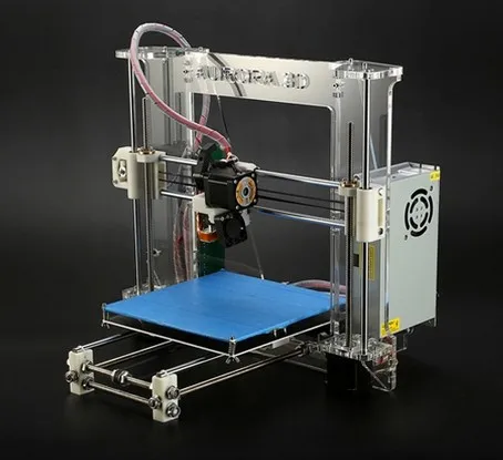
3D printer from desktop CNC milling machine
- home
- Articles
- It is interesting
- 3D printer from a desktop CNC milling machine
Installing a 3D printer print head on a desktop CNC, expands the possibilities of using a milling machine. Process control is also possible using the MACh4 program, widely known in the CNC environment.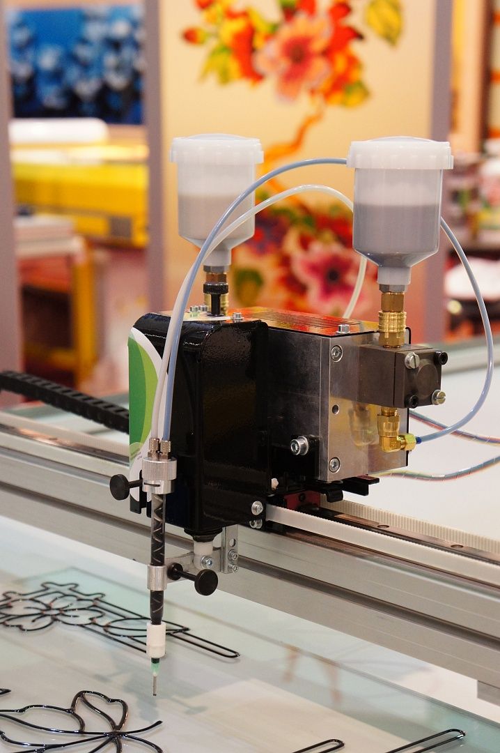 3D printing requires an STL file, which is supported by all 3D printer software. To convert to STL, you can use Soildworks, google Sketchup and other programs.
For 3D printing on a desktop CNC machine, we use a 3D printer extruder, having previously replaced the temperature sensor with a type K thermocouple, or purchase it in our store
2. To mount the spool of 3D printing filament, we assemble the rack from an aluminum profile
3. Fix the rack with the spool of 3D printing filament on the desktop CNC machine
4. Install additional software.
4.1 From http://cnc2printer3d.wordpress.com/software/ download Mach4 Addon conversion version 1.2, file setup1.2.exe.
Mach4 Addon installation package contains Skeinforge software, needed to be able to convert 3D files to G-code.
4.2 Download and install python language support https://www.python.org/download/
4.3 Run Mach4, select Mach4mill as usual.