How to make a 3d scanner with arduino
Arduino 3D scanner
Help me by sharing this post
Share
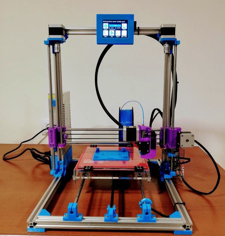
What’s up my friends, welcome back. Almost all of my DIY project have a 3D printed case of some sort of printed part. To print an object, you first need the 3D file. You have the file, you print the object. This project will do just the opposite, you have the object you get the 3D file. This machine should be able to 3D scan small objects with dimensions up to 13cm in the x and Y directions.
See the full part list here:
PART 1 - Building the frame
Below you can find a link for the STL files for the frame. Download it and print the files using your 3D printer. I've used 2 perimeters, 20% infill, 0.4mm nozzle and 0.2mm layer height.
Get STL files here:
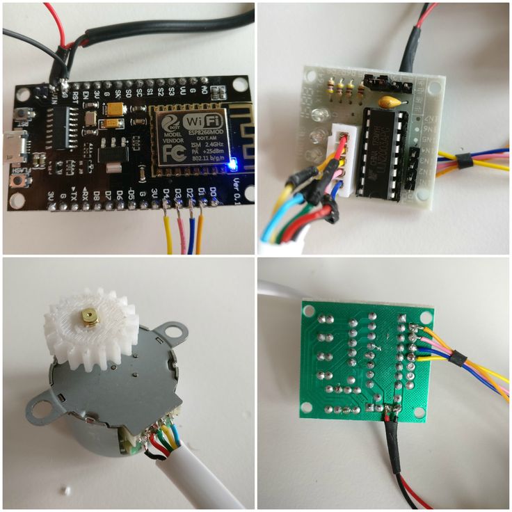
Follow this steps and build the frame. Place the two NEMA17 motors in place on the frame base. Fix them in place with M3 screws and the printed top parts. Now, fit in place the two smooth rods. Prepare the Z-axis carrige with the linear bearings. Use zip ties and fit those in place and then, add a 8mm nut on the back.
Now place the carrige on the smooth rods, add the plastic pulley on the shaft of the motor and put the threaded rod or lead screw. Finally, add the turntable on the front motor.
The sensor will give a direct analog output according to the measured distance. Finnaly, add (or not if using no homming code) the limit switch for the Z-axis. This limit swithc is used to home the axis at the beggining of the code loop when we start the machine. The frame is ready.
PART 2 - 3D scanner schematic
This below is what we need for the electronics part. The schematic is with an end stop limit switch. If you don't want to use it, make sure to later upload the code without limit switch. The push button is used to start the scanning process. Remember to connect Vref to 3.3V. We do that because the amximum voltage of the sensor is 2. 4V. To increase precision, we use external voltage refference for the ADCs.
See the full part list here:
I've made all teh connections on a drilled PCB. We have the Arduino NANO with female pins so we could remove it. The SD card module on the side and the rest of the components. The input of 12V will eb connected to those two screw PCB connectors. I've used 0.1mm wire to make the connections. Remember to add those 47uF capacitors for the motor drivers. Connect the wires from the motors and sensor to the PCB. Make sure the rotation is in the desired direction. If not, juse reverse the motor inputs.
PART 3 - The code
Let's see the code. Don't change anything in the code. Just the first variables at the beginning of the code acording to the parts you have used and the layer height you want. You have a code for the schematic using limit swithc for z-axis and for the manual homming. Download from below the code you want to use.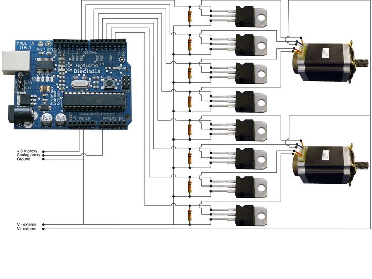 If you don't have the limit switch connected, just use the other code.
3D scanner code (
with limit switch):
3D scanner code (
)
//Editable variables int scan_amount = 40; //Amaunt of scans for each point. The result is the mean. This would increase the delay for each scan. String file="scan_001.txt"; //Name of the saved file on the SD card int z_axis_height = 12; //in cm //Maximum height of the scaned file int step_delay = 3000; //in us //Delay for each step for the stepper motor in microseconds float z_layer_height = 0.5; //in mm //Layer height. The amount of mm for each layer. int lead_screw_rotations_per_cm = 8; //How many rotations needs the lead screw to make in order to make 1cm. int steps_per_rotation_for_motor = 200; //Steps that the motor needs for a full rotation. int distance_to_center = 8; //In cm.Distance from sensor to the turntable center in cm
Read all the comments in the code for better understanding. The code is simple. Create a loop that will make 360º rotation of the turntable. Each step we measure the distance. The X and Y increment is given by simple trigonommetry as seen below. Next, the x, y and z variable are stored to the SD card divided by a "," character. This step is important for later.
PART 4 - Point cloud to STL
Place the object on the turntable in the middle. Connect power supply and wait for theamchine to home itself. When reached, press the scanning push button and wait. Depending on the layer height you choose and object size it will take more or less to complete. Once complete, remove the SD card.
Remove the SD card and copy the file to your PC. The file should have the next format. Three columns separated by a comma with the values of the x, y,and z coordinates. This are just points in a format of a point cloud.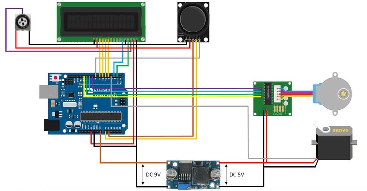 To obtain an STL file, we use the MESHLAB software which you could download from a link below.
MESHLAB software (
windows):
Use MESHLAB
Downlad and install MESHLAB with the default install. Open meshlab and go to file, inport mesh. Here open the scanned file. In the next window select XYZ format and as a separator select the comme ','. Now the point cloud is open. We haev to give normals to the points. For that go to filter, normal curvature and orientation, compute normal for point set and in this window play with the settings. 10 was a good number. Click apply and close the window.
Now go to filter, remeshing simplification and reconstruction and here select screened poisson surface reconstruction. Play with the settings if you want and then click apply. Close the window and there we have our file.
Now, the file was scanned. The precision is not that good.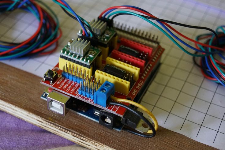 For learning purposes, this project is more than enough.
So, there you have it guys. The precision could get better using a better distance sensor. Maybe a laser based one would give better precision. Also have in mind that in the code, the sensor makes 40 measurements and give the mean of those in order to increase precision. Consider using a lead screw instead of a normal threaded rod, better sensor, more measurements, add an end stop switch and improve this project however you want.
Help me on PATREON.
See more tutorials
Help me by sharing this post
Share
6 DIY 3D Scanners You Can Build at Home
Creating a 3D model of a real object can be done extremely fast if you have a 3D scanner at home. The problem is: 3D scanners are expensive to buy new.
If you're looking for a solution, why not try building your own affordable 3D scanner at home? It might not create perfect 3D models, but it's a cost-effective alternative to buying a 3D scanner.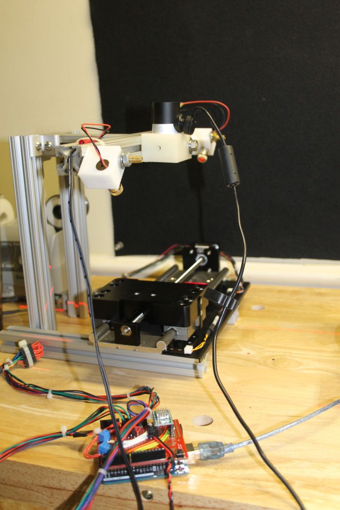
Is It Cheaper to Build a DIY 3D Scanner?
The cost of buying a decent 3D scanner ranges from $700 to $10,000 at the highest end. On the other hand, building a DIY 3D scanner can cost less than $200—some even as little as $35.
Depending on the resolution of your homemade 3D scanner, you will still have to work to tidy up the 3D model so that it can be used for things like 3D printing, game development, or perhaps design prototyping. But overall, it will still speed up the design process when compared to building a model from scratch.
1. Cheap 3D Printed 3D Scanner
This 3D scanner is built using 3D printed parts, featuring both open source software and open source hardware files. If you choose to install the maximum of four lasers, then the cost of the project comes in at $35 to $50. Once it's built, handling the digital scan will require some legwork to smooth out. But considering its price tag, it's well worth giving it a go.
You can find the STL files and a full build guide on Instructables.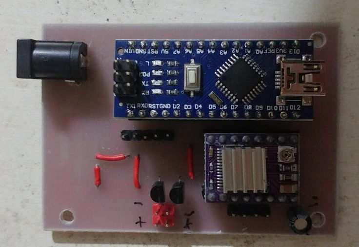 Besides the 3D printed components, you will need one to four lasers, a stepper motor, a turntable, and an Arduino Nano to bring it all together. One benefit of this project is that it's been built many times by community makers, resulting in plenty of images and feedback surrounding the project to help fill in any gaps.
2. DIY 3D Scanner Using a DSLR Camera
Another option for building a 3D scanner is to use a DSLR camera and a method called photogrammetry. At its most basic, it involves taking a lot of images of an object from different angles and stitching those photos together in a software program to create a 3D model.
Alongside a DSLR camera, you will need an Arduino, a stepper motor and driver, an LCD screen, and an IR LED. The goal of the hardware is to build a rotating platform that moves by set amounts so that your camera can photograph the object in a very detailed and controlled way. You can find a great explanation of the project on Instructables.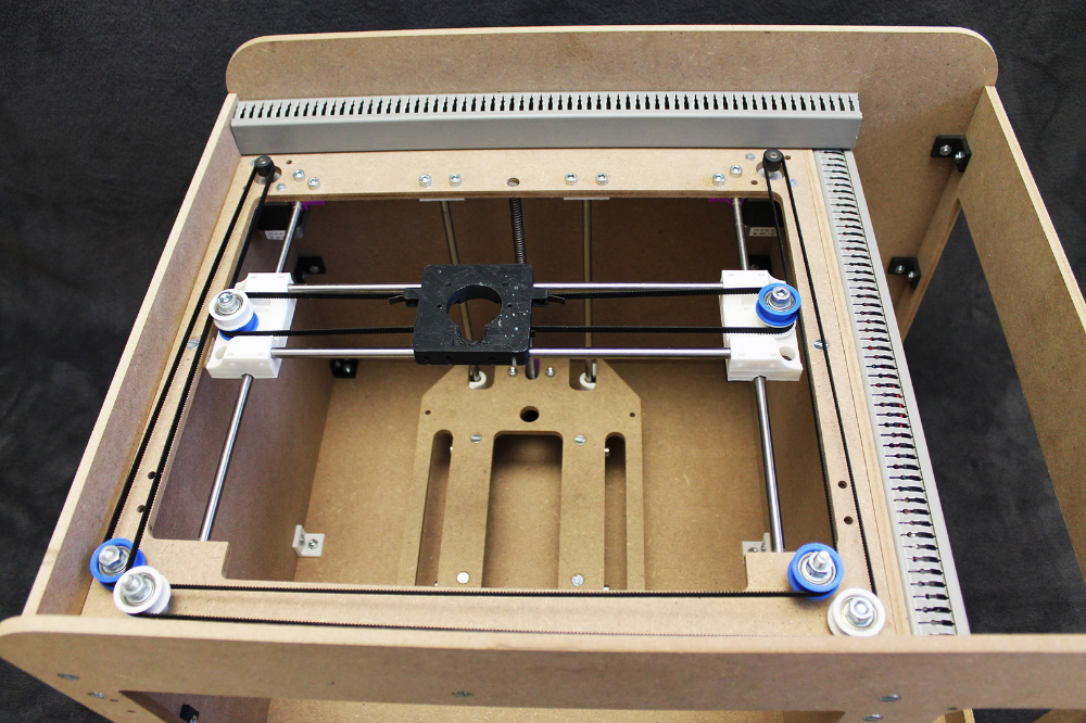
The real difficulty of this project comes in processing the photos. A good photogrammetry program is essential, and that can cost over $150 to license. There is some free software available, but it may come with limitations.
If you're wondering if there is an alternative solution, you can read our guide to how to turn everyday objects into 3D models without a 3D scanner.
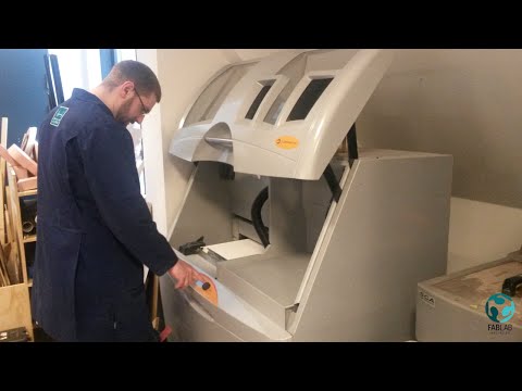
3. Optical CT/3D Scanner With Arduino
For something a little different, in this project you will build a 3D scanner that also doubles as an optical CT scanner. This type of scanner will do the trick if you have objects that are semi-transparent, like a gummy bear or a segment of orange. Otherwise, you can use this setup with the photogrammetry method for regular 3D scans.
Everything in this build is enclosed inside a box. This allows greater control over lighting the object to produce sharper images. While it involves some woodworking and construction, the hardware is still powered by a humble Arduino Nano, plus additional parts that you can find at any hardware store.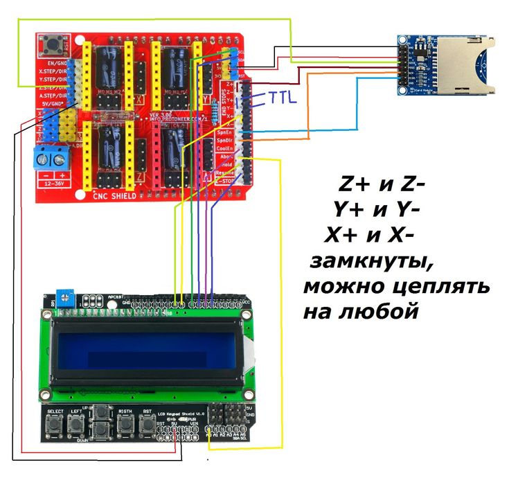
A great guide is available on Instructables for building the box, alongside details for creating a sleek control panel for changing photo parameters on the go.
4. FabScan: Raspberry Pi + Arduino 3D Scanner
This 3D scanner uses both a Raspberry Pi and an Arduino to build a 3D laser scanner. What sets this build apart is that it can be operated remotely via a web browser on a phone.
Much like other DIY 3D scanners, a stepper motor and driver are used to rotate a turntable holding the object you want to scan. Additionally, you will need a line laser and a Raspberry Pi camera. You can find the guide and a full components list on Instructables.
While the creators have gone with a laser-cut MDF box, you can just as easily use spare parts lying around the home to create the enclosure. Alternatively, cardboard can work too, and painting it black will aid in diffusing the laser light so that it doesn't interfere with the scan.
Once you have a good scan of your object, you might be interested in 3D printing it.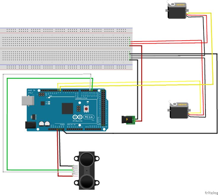 Haven't got a 3D printer? Here is our pick of the best 3D printers.
5. The Ultimate Human Sized 3D Scanner With Raspberry Pi
While most homemade 3D scanners are built to capture a small object, it's also possible to build a human-sized 3D scanner. The way to do this is with a lot of Raspberry Pis, as you can see over on Instructables.
The maker behind this project scaled up his 3D scanner using a whopping 47 Raspberry Pis plus a Raspberry Pi camera for each module. The goal was to use the photogrammetry method to take a photo of his subject from every possible angle. Because he wanted to capture a 3D model of his two-year-old son, this all had to happen instantly.
Incredibly, it works, and it works very well too. If you have the time and investment to buy a box full of Raspberry Pis, you won't be disappointed because the results are impressive. The maker says you can use fewer Pis and cameras and still get good results, especially if you only need to capture the front of a person’s face.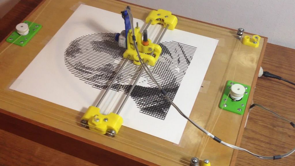
6. Standalone 3D Scanner
Maybe you're just after a simple and small 3D scanner that you can make over the weekend. If so, then this project will suit you. This 3D scanner on Instructables is designed to be all-in-one, meaning that the photos are compiled onboard and an STL file is saved directly to a memory card. Instead of compiling the photos in a separate photogrammetry program, this 3D scanner handles them for you.
While it doesn't produce incredibly detailed scans, it does make for a rapid way to take a 3D model straight to 3D printing. One thing to bear in mind, however, is that the dimensions of the 3D scanner structure need to be kept exactly as written in order to match the code.
Building a Homemade 3D Scanner
Putting together a 3D scanner at home isn't extremely difficult to achieve. When compared to the expensive price of commercial 3D scanners, it's well worth building a DIY 3D scanner yourself.
With a Raspberry Pi or Arduino and a few extra affordable parts, you'll be well on your way to creating a cheap and awesome 3D scanner.
News
Subscribe to the author
Subscribe
I do not want
14
Enthusiast under the nickname QLRO posted the project of a simple desktop photogrammetric 3D scanner assembled from smartphone, microcontroller arduino and 3D 3D - printed parts.
To assemble the device, you will need a minimum of components, plus an Android smartphone and a computer. The rotating platform and smartphone stand can be 3D printed. In the original project, the platform is rotated by a 28BYJ-48 stepper motor with an ULN2003 driver and controlled via Arduino. Scanning is carried out by photogrammetry, using the built-in camera of a smartphone. nine0003
The system relies on Meshroom photogrammetry software. As the developer explains, the software requires the use of an Nvidia graphics card with CUDA hardware and software architecture. The operation of the device components is coordinated by scripts written in Python: the computer sends commands to the Arduino and the smartphone to rotate the platform and shoot, and after shooting the object from all angles, the images are converted into a digital model. In the current, third version of the software, it is possible to use several cameras at the same time, but so far on an experimental basis. nine0003
The author posted all the necessary files and instructions in the public domain on the Thingiverse website at this link.
3D scanner desktop AAScan QLRO
Follow author
Follow
Don't want
14
Article comments
More interesting articles
12
Subscribe to the author
Subscribe
Don't want
Scientists of Sechenov University, Baikal Institute of Nature Management, Siberian Branch of the Russian Academy of Sciences. ..
..
Read more
eight
Follow author
Subscribe
Don't want
The project was implemented by employees of the Smart Build construction equipment factory, who provided addit...
Read more
59
Subscribe to the author
Subscribe
Don't want
The 3Dtoday portal, supported by Creality and Bestfilament, invites everyone to participate in...
Read more
Read blogs
Almost DIY 3d scanner for home / Sudo Null IT News scanning is out of the question.
But the main plus that I took out from the article is the David-3D scanning program, which really has a good manual in Russian and, importantly, buying a license is the last thing required, since the free version is limited only to saving the scan result.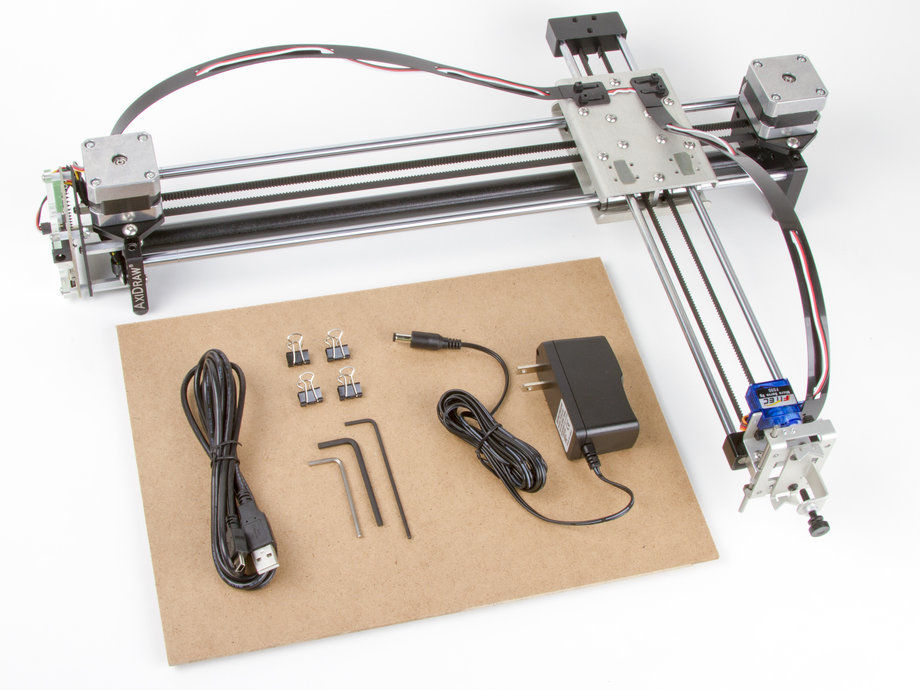 Everything else works in full, which means that it is quite possible to test the program, settings and your hardware as much as you like. And if you don’t need the result with high accuracy, then you can do without buying a license at all. nine0085
I needed accuracy, since the main thing I wanted to scan was miniatures from the Warhammer board game (so that later I could change them as I wanted and print them :)). The height of these "soldiers" is only 3 cm, but this does not prevent them from being very detailed.
If you do not need to shoot such small objects, then your equipment requirements will be lower, which means that it will be much easier to assemble a similar scanner for yourself.
The principle of the program, and accordingly scanning, is well described in the article, which was linked above (I think it is not necessary to duplicate this). It is advisable to read that article first, as this one will be in some way its logical continuation.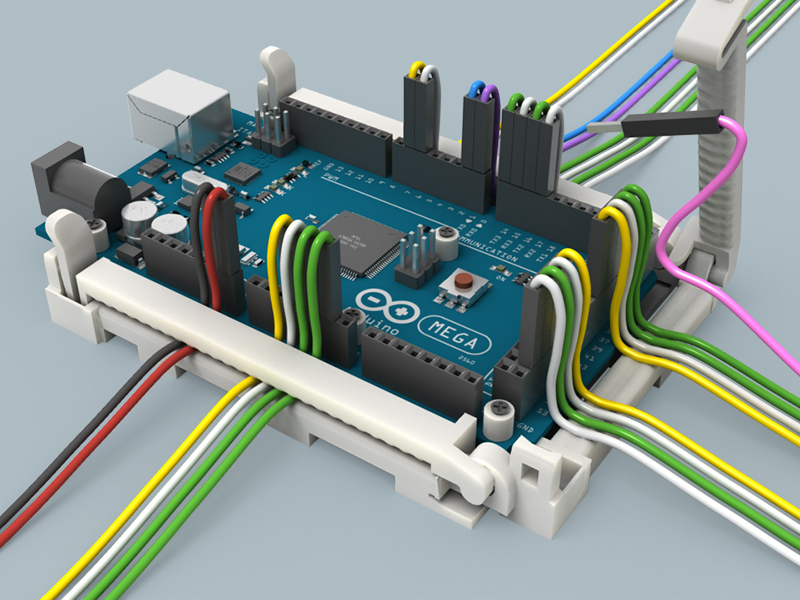 nine0003
But let's start in order. What you need to try 3D scanning at home:
1 - projector.
2 - webcam.
That's all, the short list turned out surprisingly well. However, if you want to get very accurate and high-quality scans, then you will have to modify some things with pens. Of course, you can’t do without additional costs, but in the end it will still cost less than buying any of the commercially available 3D scanners, and the quality of the result can be obtained much better. nine0003
Now, in order and in detail.
PROJECTOR.
I, like the author of the previous article, started my first experiments on scanning with a laser pointer, but they immediately showed how inconvenient this method is. There are several disadvantages here at once:
- the impossibility of obtaining a beam with a sufficiently thin line. Moreover, when you turn the pointer, the distance from the lens to the object changes, which means the focus is lost.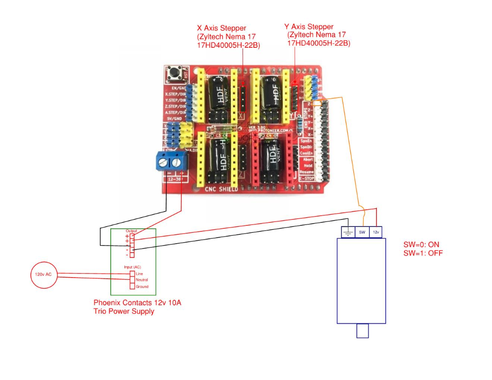
- if you need to scan regularly, turn the laser pointer with sufficient accuracy and smoothness by hand is very difficult, and tiringly easy - the hands are not such a stable tool when it comes to a long time. nine0085 - you have to scan in the dark so that only the laser line is visible and nothing more.
And if the second drawback can still be dealt with by creating a special rotary mechanism (although this is already not such an easy task, in any case, this cannot be done in 5 minutes on the knee), then getting rid of the first drawback is more expensive.
When I realized all this, I decided to try scanning with a projector, for which I borrowed some simple model from a friend. nine0003
A small clarification should be made here - in the last article, the author mentioned the possibility of scanning using a projector, although the proposal was, in my opinion, very strange -
A projector with a powerful lamp will do, the light of which must be directed through a narrow slit to the object being scanned
This may have been the only option in earlier versions of the program, but in version 3 that I experimented with, the projector was used much better, because there's a feature called Structured Light Scanning (SLS).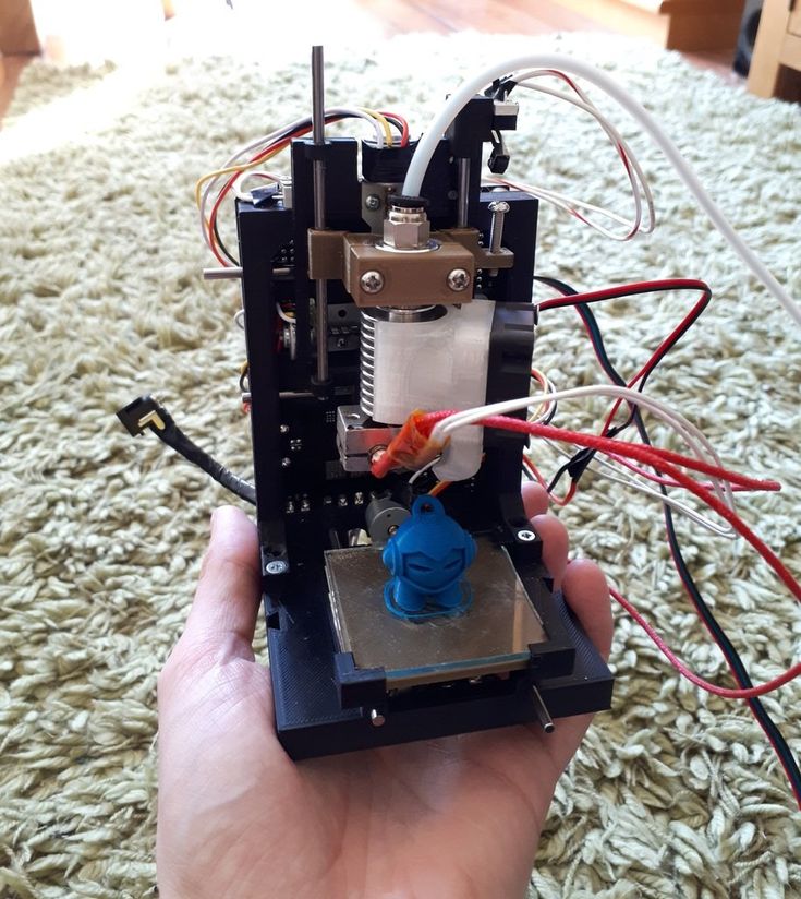 Unlike laser scanning, the projector immediately projects a grid of vertical and horizontal lines of various thicknesses onto the object, which reduces the scanning time by an order of magnitude and allows you to automatically shoot the color texture of the object. Well, with good focus, a 1 pixel wide line is much thinner than you can get from an inexpensive laser pointer. nine0003
Unfortunately, I didn’t take pictures from those first experiments, and there wasn’t much to take pictures of - the projector is on the table, next to it is a webcam, all of this looks in one direction :) However, even such a simple design showed that this option much better both in terms of scanning speed and quality. Then I decided to buy myself a projector for these purposes.
The criteria for choosing a projector were simple - higher resolution, lower price and dimensions :)
The choice settled on IconBit Tbright x100 - an ultra-compact DLP LED projector, 1080 resolution - at that time it seemed to me that you couldn’t imagine better, but as it turned out later, I was wrong, although while working with it, I got a lot of interesting experience.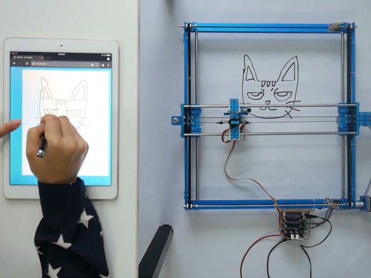 nine0003
The first problem that occurs when scanning a small object with a projector is that for best results, the size of the projected grid should roughly match the size of the object being scanned. This projector made it possible to obtain the smallest screen diagonal at the closest focus - about 22 cm. Agree that against such a background, a miniature 3 cm high is far from the concept of "approximately equal sizes." The answer was found on the official forum - people in such cases install camera lenses on the projector for macro photography. Given the small size of the projector lens, I opted for marumi lenses with a thread diameter of 34mm. nine0003
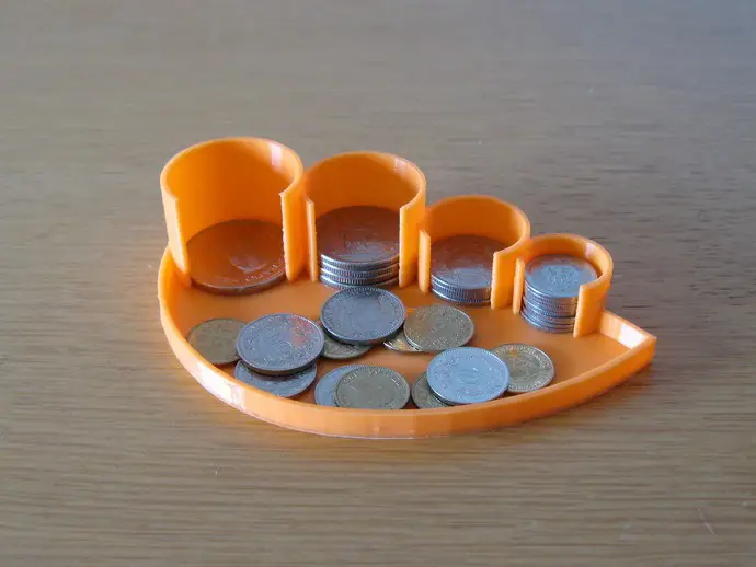
Using two of these kits, I managed to get a projector screen with a diagonal of only about 3 cm. Which turned out to be quite enough to make my first microscan -
This is a single scan, therefore there are “holes” on the model, torn edges and etc. By turning the coin and scanning from different angles, you can get several of these scans, which are subsequently combined into one object (the scanning program itself allows you to correctly combine different scans, stitch them together and save them as a single object). In the process of stitching, the shape of the object is also specified. But saving the results of such stitching is possible only after purchasing a license. nine0003
And now the moment has come for the first thing that is not necessary for scanning, but with it the process is much more convenient - this is a stand for a projector with a camera. The calibration process itself is needed not only for the program to recognize the parameters of the equipment - the software must also calculate the relative position of the camera and the projector. In the course of work, their change is not allowed (as well as changing the focus of the camera), which means that it is necessary to firmly fix all this, because the number of scans can be large even for one object. nine0003
David's main page shows a similar system - it is nothing complicated. Yes, and looking through the forum and seeing how different people organize it for themselves, I realized that nothing complicated is required here.
For these purposes, a stand was taken from a burned-out LCD monitor, and plexiglass from it, cut and glued like this design, as it looked in the first version , which allowed changing the screen diagonal and scanning objects of different sizes. nine0085 It should also be mentioned that scanning with a projector does not require the constant presence of calibration panels in the field of view. After the calibration is done, they can be removed. This allows, having calibrated the installation, to easily transfer it, move it, etc.
That is, you can use a large calibration template to calibrate at home on the walls, and then go outside with this stand and laptop and scan your car, for example. We took a smaller template, put a couple of lenses - and you can scan jewelry. nine0003
Recently, the company has released an improved scanning kit, here the stand looks much more serious and interesting -
2000 euros is not entirely justified, it is not difficult to assemble something like this yourself and much cheaper.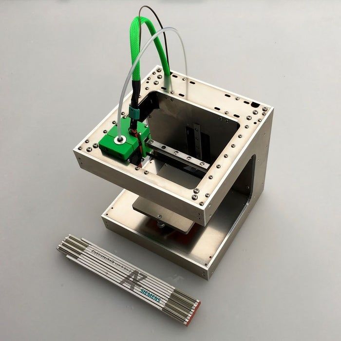
Let's go back to the projector. As it turned out, this projector had one major disadvantage for being used in a scanner, namely its native resolution (854*480). And everything would be fine if it produced the same output, but alas, the picture was converted to standard resolutions (such as 1024 * 768), and as a result, a line one pixel wide was somewhere brighter in different parts of the screen, where - something dimmer, somewhere already and somewhere wider ... All this had a negative effect on the quality of scanning, expressed in the form of ripples and stripes on the resulting model. nine0085 By that time, I was already thinking about buying a projector for a stereolithographic 3D printer (http://geektimes.ru/post/245590/). After considering several options, I settled on the Acer P1500 model, because. it does not need any modifications to be used in a printer (this projector, without any lenses, is able to give a focused image on a screen of about 4 * 7 cm). So, for the scanner, it will fit perfectly.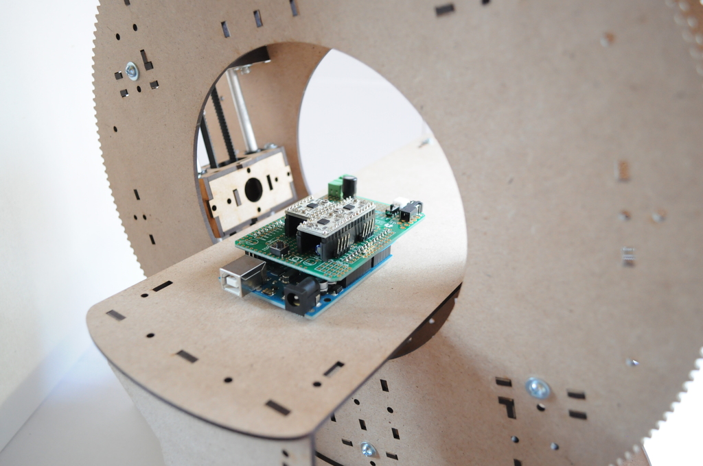 At the same time, the resolution of 1920 * 1080 is real. And so it happened, I still use this projector and am completely satisfied with the results. nine0003
CAMERA.
The criteria for choosing a camera were the same as when choosing a projector. Having gone shopping, I stopped at the Logitech C615. The scan of the coin was made from it, without any modifications. But when I tried to scan the figurine, I ran into a problem called "depth of field". When the object is so small, then in fact we get macro photography, and sharpness with such shooting is achieved only in a small segment, literally just a couple of millimeters (which is why the coin was scanned well - the relief fit perfectly into the sharpness area). It was decided to convert the camera to a different lens. Several different lenses were ordered on Ebay for testing, and a new case was cut out for the camera board. The plan was like this0003
The final result was slightly different
The main idea, I think, is clear.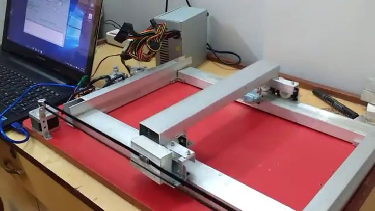 And now, both on Thingiverse and on the forum of the program, you can download stl for printing cases for different types of webcams.
I had to remove the standard lens from the camera board, and as it turned out later, the IR filter was removed along with it, so be careful in this matter. The filter will then come in handy for use with other lenses, although you can buy them separately - the price is cheap. nine0003
Thus, I have formed such a collection of lenses.
While I was waiting for the lenses to arrive, I was reading various photography forums. Studying the issue with depth of field, I found out that you can increase it by closing the lens aperture more. This means that the lens was required one in which it was possible to adjust the aperture (alas, among those ordered, not everyone had such an opportunity, but luckily I got a couple of them). In general, to improve the camera, it is desirable to have a varifocal lens with a zoom and an adjustable aperture.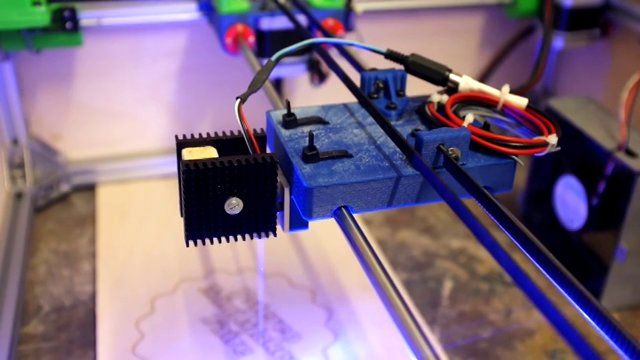 In practice, everything turned out the way it was in theory - closing the aperture, an increase in the depth of field was immediately visible, which made it possible to scan three-dimensional, but small objects. nine0003
The main lens I use is mounted on the camera in the photo above. The second, with an adjustable aperture, is the largest, in the center. I use it for very very small objects. The rest are without a diaphragm, so I don’t use them - it turned out that these two were quite enough.
Now I plan to either find a webcam with a higher resolution (the quality and detail of the scans directly depends on the resolution of the camera), or try to use some digital camera for this purpose with the ability to shoot video - usually you can get a lot more resolution in them, and lenses are better. nine0003
Actually, this could be the end - it seems that he told about everything. I also thought that this was the end of my scanner assembly, but the farther into the forest .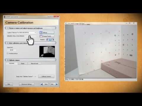 .. While studying the forum of this program, I often came across various schemes of turntables - fortunately, the software allows you to automate the scanning process. After one scan, a command is sent to the com port, the turntable rotates, turning the object by a given number of degrees, and gives a command to the next scan. As a result, with one click of the mouse, we have circular scans of the object - it would seem, what more could you want? I tried this system with interest, but alas, I absolutely did not like this approach, and there are a couple of reasons for this. nine0003
1 – if the object has a complex shape, then simply rotating it will not be enough – you also need to tilt it in different directions so that the camera with the projector reaches all the depressions and other hard-to-reach places.
2 - even if there are no such places, and considering all the scans that were made, there are no parts left on the object that did not fall into the scan, the question of the accuracy of the scan remains.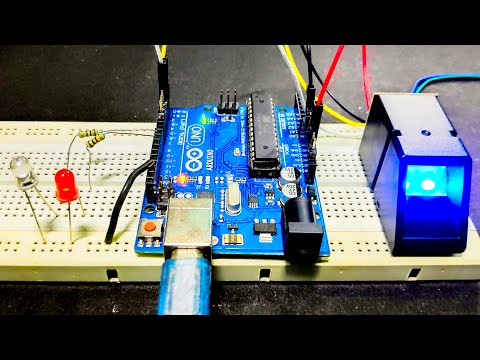
Let's say that some part of the model on one of the scans came out perfectly. But this does not mean that on all the scans in which this part fell, it also looks perfect, and when stitching scans from different angles, the result will be averaged, which cannot please. The program allows you to slightly edit the received scans (you can cut out the unnecessary part). If we rotate the model by 20 degrees, then after a full rotation we will have 18 scans, the part we need may well be present on half of them, therefore, in order to leave the best result, we will need to remove this piece from 8 scans ... And such pieces with a complex There can be many models, as a result, almost half will be cut off from each scan, which is very laborious and time consuming. nine0003
Instead, it is better to immediately scan adjacent areas after the first scan and check the result. As soon as a piece is ready, we move on to scanning the next one, and so on, until the entire model is in perfect shape.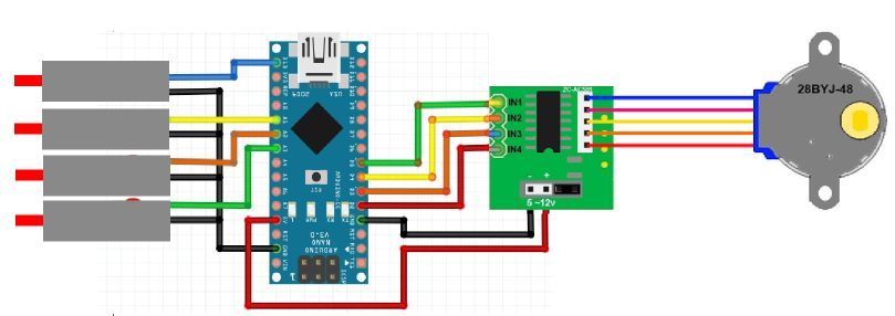 This approach gives the best results in less time.
But the question of convenience arises. Agree, it’s inconvenient to manually try to rotate an object, looking not at it, but at the monitor - in order to control the hit on the lens without changing the distance to the camera and the projector at the same time (so as not to lose focus). With the next similar balancing act, I accidentally touched the camera, which accordingly knocked down the entire calibration, and the whole process had to be started anew. I categorically did not like this alignment, and after some thought I came up with a plan for such a design (which, as you understand, I subsequently assembled). nine0003
This is not a turntable in the usual sense of the term. Thanks to this design, I can not only rotate the model, but also tilt it as I need. In this case, the center of the model remains in the plane of focus, but even if not, you can move the mount with the model back and forth.
All this was assembled on arduino, a small control program was written, and as a result, now I don’t have to get up from the computer when scanning - using the program, I change the position of the object being scanned, and at the same time, right there, in the window cameras I choose the best angle for scanning.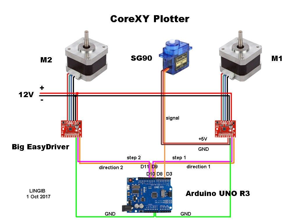 nine0003
Entrails
I put in the program the possibility of automatic scanning, as well as scanning not only in a circle, but with inclinations of 45 degrees in one direction and the other, which gives three times more scans. Nevertheless, in the end, I still never use this opportunity - it's too inconvenient to sort through the resulting pile of scans and clean them from unsuccessful pieces.
We should also mention some nuances of scanning.
1 - it is impossible to scan shiny and mirror surfaces. The light from them is reflected, or gives such a glare that the program cannot correctly recognize the line. If there is a need to scan such an object, then such parts will have to be masked with something (washable paint, paper tape, etc.). nine0085 2 - it is more convenient to scan monotonous objects, since when the camera is set to a light color, the projector's brightness is not so high, the exposure is low, etc. And a dark-colored object needs more brightness, so if you have a multi-colored object, then different parts of it require different settings to get the best result. Here, too, it is more convenient to use scanning the object in parts.
3 - if you want to immediately get a color texture, then please note that the settings of the camera and the projector for scanning do not affect the settings for removing the texture (the scan is generally done in black and white mode), so play around with the settings in the texture mode just as you would do in scan mode. nine0003
My scanning process now looks like this:
- Focusing the projector and camera
The projector's light is too bright and the projected grid is not visible in the photo, but here is the view from the camera in the program
- scanner calibration
printed on magnetic paper - so you can very quickly adjust to different sizes of scanned objects. nine0003
Software view
It is recommended that the combined angle between the beam of the projector and the camera be around 20 degrees. Therefore, such a stand is used - when scanning large objects (for example, a person), the camera should be set aside much further from the projector, but here they are close to me. The location of the camera relative to the projector can be only vertical, or only horizontal, depending on the geometry of the object. In this case, the arrangement is diagonal (13 degrees vertically and 36 degrees horizontally). nine0003
Scan results from different angles. These are already cleaned up scans, i.e. all unsuccessful and unnecessary parts (figure stand, mount that got into the frame) parts have been removed.
Combining scans for subsequent merging into one object
Due to the fact that each scan has its own color, it is convenient to control the correct alignment.
Well, after combining the scans from different angles, we get the following models
Miniature of Boromir from Lord of the Rings. nine0085
When scanning a multi-colored object, the result is slightly worse if you do not bother much. But then you can get an object immediately with a texture :)
Original models
In the gallery of user works on the developer's website (http://www.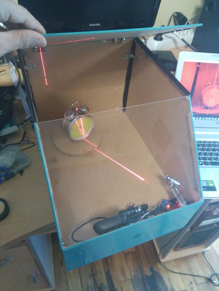 david-3d.com/en/news&community/usergallery) you can find many more interesting scans , even fingerprints people scan. And there are even scans of the same miniatures from Warhammer
In conclusion, I would like to say that no matter what hardware you use, no matter what expensive 3D scanner you buy, this is not a panacea for printing anything. Theoretically, of course, you can send the resulting object to the slicer and print, but there are several reasons why you should not do this, but in any case, you should study 3D graphics packages. nine0003
1 - The resulting scans, with good scan quality (and we want to get the best quality) have a lot of polygons. No, even is VERY a lot. The scan of Boromir after the merger contained more than 8 million polygons - not every slicer will be able to work with such an object.
2 - Any objects bear traces of assembly and manufacture. And if in reality needle files and sandpaper are used to fix this (and sometimes there are still inaccessible places where it is impossible to use tools), then working with a digital copy of an object, we can change it as we like - remove defects, improve detail, etc.