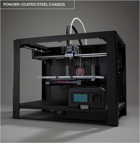
Cnc from 3d printer
What's the Best Way to Make Your Part?
Introduction
The development of stronger 3D printing materials has encouraged manufacturers across industries to explore CNC vs 3D printing, and find ways to 3D print functional parts that were previously CNC machined. The 3D printing process can save manufacturers considerable time and money, while still generating the quality necessary for industrial-level production.
Manufacturers that make the switch can leverage 3D printing software to prototype and produce parts in a single day, for a fraction of the cost of traditional CNC machining. However, there are still several key areas where CNC may still be the right choice for part production.
From physical to financial, let’s walk through some of the key areas to evaluate before deciding between CNC vs 3D printing.
Read our 3D Printer Buyer's Guide
Physical Considerations
Geometry
Feature Size: Both CNC and 3D printing processes are constrained by tool size; in the case of CNC, the tool diameter dictates the smallest negative feature that can be created. In the case of 3D printing, however, the nozzle diameter dictates the smallest positive feature that can be produced. The nozzle diameter for extrusion-based 3D printers is typically between 0.25mm and 0.8mm, and the minimum feature size for those machines is 4 times that, resulting in a minimum feature size between 1.0mm and 3.2mm.
For more detail on minimum feature size for continuous fiber reinforcement, we’ve created a guide to minimum fiber feature sizes.
Surface Finish: With the right tools, CNC machines are capable of producing much smoother surfaces than 3D printers. 3D printers are capable of producing parts for fit and finish, but for parts that require exceptional smoothness for mating with other precision components, CNC machining may be preferable.
Tolerances: Some of the best composite 3D printers can hold dimensional tolerances down to +/- 0.005”, and typically have a compliant surface for press fitting. Tight tolerance features on 3D printed parts can be post-machined. However, depending on the other features on the part, it may be easier to machine the whole thing. Your results may vary based on machine, material, and part geometry.
Get a free sample part
Loading: Non-structural parts are typically easy targets for conventional 3D printing. Structural parts that need to withstand significant physical loads can be produced with continuous fiber reinforcement, or by CNC machining. While continuous fiber reinforcement can provide significant strength improvement over other 3D printed parts, composite parts are stronger in two axes (X, Y) than in Z, and do not exhibit isotropic properties like metal parts. To learn more about how this might affect designs and orientation of parts for printing, read this piece on Isotropic Fiber Fill, which explores these parts in greater depth.
Check out our white paper on how to 3D print your own tools and fixtures
Environment
3D printing and CNC machining are both capable of producing parts in metals and polymers, so the choice will revolve around which process is more readily available for forming the material that you need.
Temperature: 3D printing and CNC machining are both capable of producing parts in metals and polymers, so the choice will revolve around which process is more readily available for forming the material that you need. The service temperature of a particular metal typically has some relation to its melting temperature. “Pure metals usually weaken seriously at about half the melting point on the absolute temperature scale (melting point in degrees F plus 459).” Alloys can typically push the useful range higher, in some cases to about 65% of melting temperature.
3D printed composites and polymers have service temperature limits lower than metals. Markforged materials typically should not be used for extended periods at elevated temperatures above 150 °C.
Moisture: Some polymer filaments absorb moisture and may lose strength through prolonged exposure or submersion. A coating, such as Liquitex, may be required. Moisture typically does not affect aluminum, but may cause steel to rust.
Chemicals: If your part will be subjected to any chemicals, check the chemical compatibility of your material with the chemical. While many metals are suitable for use with a variety of chemicals, always check for compatibility before introducing a new material or environment. Markforged nylon-based materials are chemically resistant and are unaffected by most petrochemicals. They are not suitable for use in strong acid or base environments.
Economic Considerations
When do you need it?
Machining in-house: If the part is needed immediately, there are no other holdups to the operation, and you have a machine, operator, materials, and workholding available, you should CNC machine your part. If there are more urgent jobs, or the part can wait, 3D printing can usually get you a part in hand the next day, freeing up operator time for more critical tasks.
CNC machining usually is capable of removing material much faster than 3D printing can deposit it. Size usually does not play into the time constraint as much for machining; the amount of material removal required is much more critical. If the part volume/stock volume ratio is very low (material removal is high), 3D printing may be a good option.
With 3D printing, the part size does affect time; larger parts take longer to print. if a part fits in the palm of your hand, you can usually have it the same day. With smaller parts, it can often be faster to 3D print than to machine. With a CNC machine you have to spend time getting stock, writing G-code, figuring out work holding, setting up tools, and cleaning up after. Some parts can print in the time it takes just to get a CNC machine ready.
Machining out-of-house: The process of outsourcing machined components to CNC machining services typically requires several days at minimum, between part review, creating drawings, sending out for quote, and reviewing with purchasing. This, plus shipping and lead time from the shop, can sometimes result in a very lengthy process.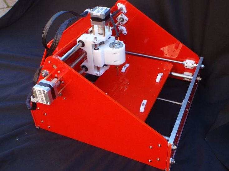 Printing, in this case, may be a suitable way to check fit and finish or have a part ready the next day while a permanent part is being cut.
How many do you need?
When you break down the cost of low-volume machined parts, the bulk of the cost comes from the time required for programming and setup; the actual time for cutting metal is generally fairly short. Scaling up production volume is generally achieved by making larger setups to cut more parts unattended. As part complexity and the number of features increases, programming time and the number of required setups may also increase. However, the cost of additional units drops off fairly quickly. Depending on geometry, CNC per unit cost scales well into orders of hundreds or low thousands of units per month since the programming and setup can be reused.
With 3D printing, the programming (slicing) happens in a matter of minutes, and complexity has little effect on the programming time. While the first unit cost and effort is low, the per unit cost is not affected much by volume.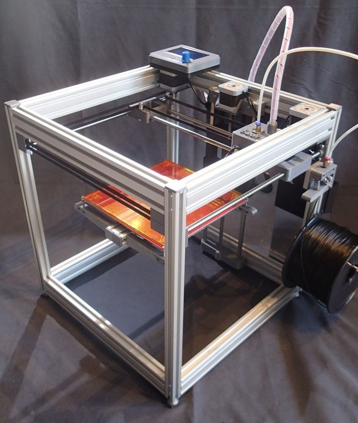 Scaling up production volume is generally achieved by bringing more machines online.
What is your budget for equipment and operators?
CNC machines can run unattended when properly set up, but typically trained full-time operators and programmers are critical to success. Machines are not always easy for owners to service, requiring expensive maintenance plans.
3D printers can easily run fully unattended, operators require minimal training, and programming is made easy by software. Machines are typically easy to service and have far less expensive maintenance costs.
CNC machines and 3D printers come in a range of prices based on features and build quality, but typically 3D printers can be owned for a significantly lower investment than a CNC machine.
The upfront cost and operating cost of additive manufacturing is low, making it ideal for low volume applications such as prototyping and tooling. However, when scaling to higher volumes, subtractive manufacturing and forming are more cost effective.
Request a demo
Where should you fall on the CNC vs 3D Printing Debate?
The case is seldom as simple as a one-to-one process replacement, and 3D printing is not going to solve all of your production problems overnight. Economic constraints limit the cost effective part quantity for 3D printing to low volumes, and the materials and process constraints may limit the application space. CNC machining, on the other hand, sees favorable economies of scale once quantities are a bit higher, usually on the order of hundreds of units per month.
When To CNC Machine Your 3D Printed Parts | Stratasys Direct
- December 20, 2017
Computerized numerical control (CNC) machining has been around since the early 1950s and is one of the most popular low volume manufacturing processes. Starting with a large block of raw material, a tool mills away material along a computer designated path to create a part.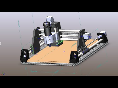 These programmed tool paths can cut incredibly precise and repeatable geometries in a variety of plastic and metal materials.
CNC machining is traditionally used to manufacture low volume, end-use parts, but it has also been adopted as a secondary process for additive manufacturing technology. Companies often will 3D print plastic or metal parts and then CNC machine them for the following reasons:
- Dimensional accuracy – Industries with high functional and tolerance requirements, such as automotive, medical and consumer products manufacturing, need to hit repeatable, tight specs. Most additive manufacturing technologies, such as Fused Deposition Modeling (FDM) and Direct Metal Laser Sintering (DMLS) can achieve up to ±0.005 in., but that’s not enough for some critical part features. With CNC machining you can bring tolerance down to ±0.002 in. which can make a huge difference if you’re producing an assembly aid, manufacturing fixture or any in-process tool with a long service life.
- Speed – The second reason why companies combine the two technologies is speed. Accounting for print time, CAD/CAM set up and machining, the process is still much faster than designing and producing a tool for injection molding. And 3D printing and machining give engineers more flexibility in the timeline to make design improvements. It just involves updating CAD/CAM files, and printing and machining a new part, whereas making changes to an injection molding tool can be nearly impossible and expensive, causing major delays in production.
The most widely used machining technique for additive manufactured plastic parts is horizontal or vertical 3-axis milling because of its ability to move in the X, Y and Z planes. For more complex features and geometries, we recommend 5-axis milling, which can rotate and tilt on the A and B-axis to reach undercuts and small features.
Parts made from direct metal laser sintering (DMLS) are often designed for demanding applications so they are almost always machined with multi-axis milling to achieve precise surface dimensions. For high-value production metal parts, companies will apply a micro-machining process that combines a chemical reaction with a fluid flow removal process to create a mirror-like surface quality. This polished surface finish is often needed for rubber gaskets to create a tight seal.
If your application requires specific dimensions, you will need to adjust your part’s 3D CAD data accordingly. There are a few things to consider when preparing your design files:
- Build in excess material – Additional material needs to be built into the raw 3D printed part so that when it’s machined, there are enough layers for the tool to remove to achieve the correct spec.
- Note areas of tight tolerance – When consulting with the service bureau project engineer be sure to show them the critical dimensions that will need to be machined. Often they recommend design adjustments to optimize the build for machining, such as increasing certain wall thicknesses or going up a tip size.
- Make critical features accessible – Place components that need to be machined to spec in an easy-to-reach area. Even 5-axis mills can’t reach some 3D printed geometries so move application-critical features to a tool-accessible spot if possible.
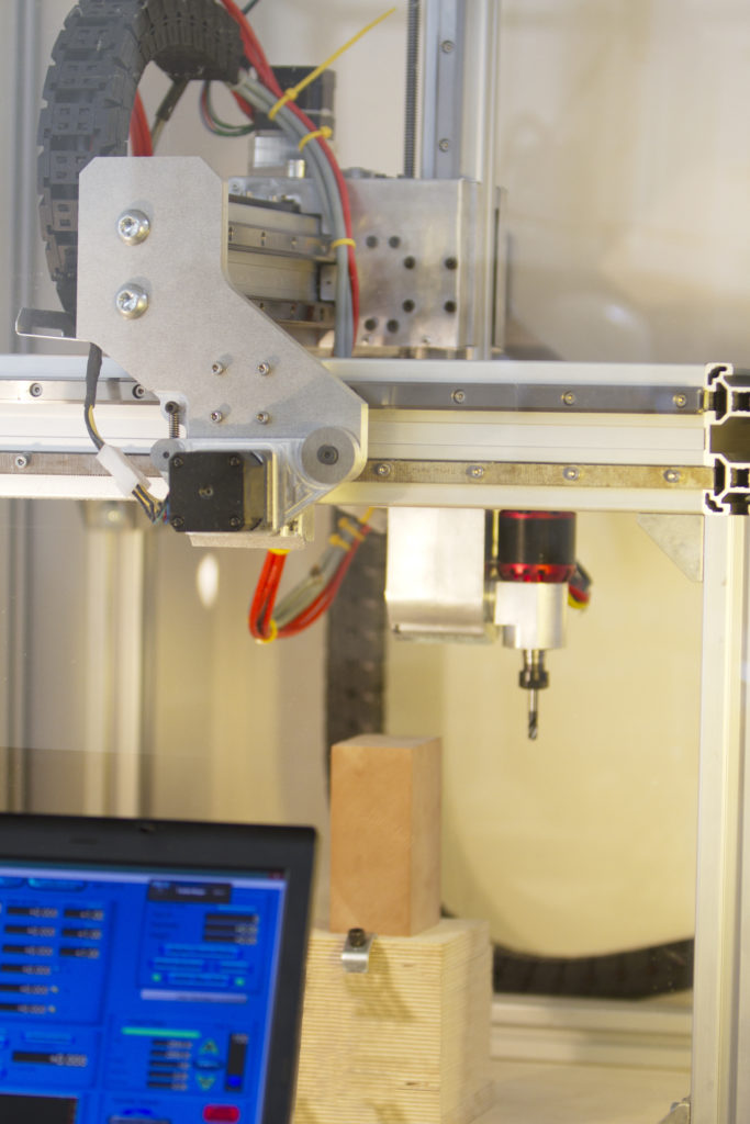
CNC machine from 3D or everything has already been done before us / Sudo Null IT News In addition, changing drills inevitably led me to miss holes or errors in diameters. It was decided to spend the day but in 5 minutes
to drill.
A short video of how it all looks in operation.
I had a purchased toy, not cheap for those times, a 3D printer called “Anet A6” on the seller's page. Why not CNC? 3 axes, 2 cooling channels, table heating and filament supply. The set was completed with an incomprehensible firmware, tk. when loading wrote "OMNI 3D PRINTER A8" + liquid plexiglass frame design. I use SprintLayout (Sprint) for drawing printed circuit boards, then laser-ironing technology. It was necessary to export the drill file in Exellion format from the Cprint program, the program has such an opportunity, and convert it into a G-code readable by the machine. The code is specific to 3D printers. It is further assumed that the first acquaintance with the theory and practice of printing is available.
We draw in SprintLayout 6 with pins the Latin letter “F”, such a figure will allow us to unambiguously determine how the image with holes on the board will look on the printer table.
After exporting the drilling file, we get a list of hole coordinates with a title.
; Drill file ; Format: 3.3 (000.000) M48 METRIC T01C0.7 % G05 G90 T01 X38.100Y-43.180 X38.100Y-38.100 X38.100Y-33.020 X38.100Y-27.940 X38.100Y-22.860 X38.100Y-17.780 X38.100Y-12.700 X38.100Y-7.620 X43.180Y-7.620 X48.260Y-7.620 X53.340Y-7.620 X58.420Y-7.620 X48.260Y-22.860 X43.180Y-22.860 M30
This format is not suitable, it is apparently for "adult" machines, there is no movement along the Z axis.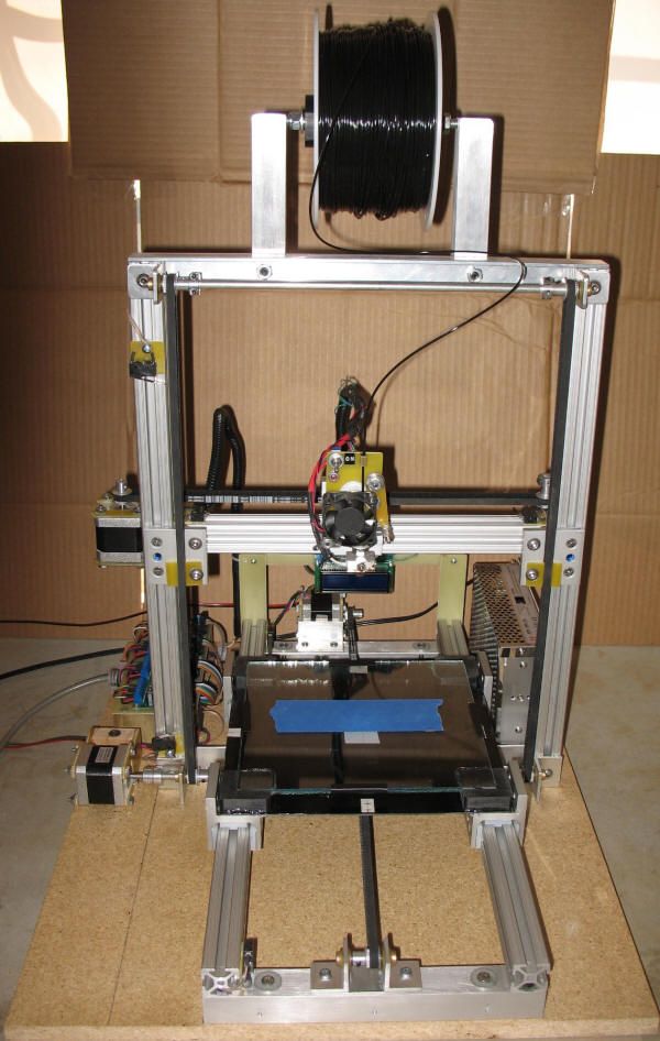 Using the very convenient Notepad ++ editor, you need to edit the file. It can create macros by recording actions and then apply them to any files.
First, delete the "head" and "tail", leaving only the coordinates. Using the "Search-Replace" menu, we look for "X" and change it to "G0 X". Next, look for "Y-" and change to "Y" (with a space in front). It should look like this: G0 X38.100 Y43.180 - the first line and beyond. Then after each line we insert the movement of the drill using a macro:
G1 F50 Z10.000
G0 F7200 Z15.000
In order not to break the tool, before the first drilling coordinate, insert a lift with a margin into the code: G0 F7200 Z50.000, the Z value can be adjusted later to speed up the workflow.
It will be cheaper to clamp into the chuck for tuning, more precisely, not a drill, but a piece of filament or cutting a rod from a handle of equal length.
Add a header and a "tail" from the G-code file of any model obtained in Repetier Host by the Cura slicer.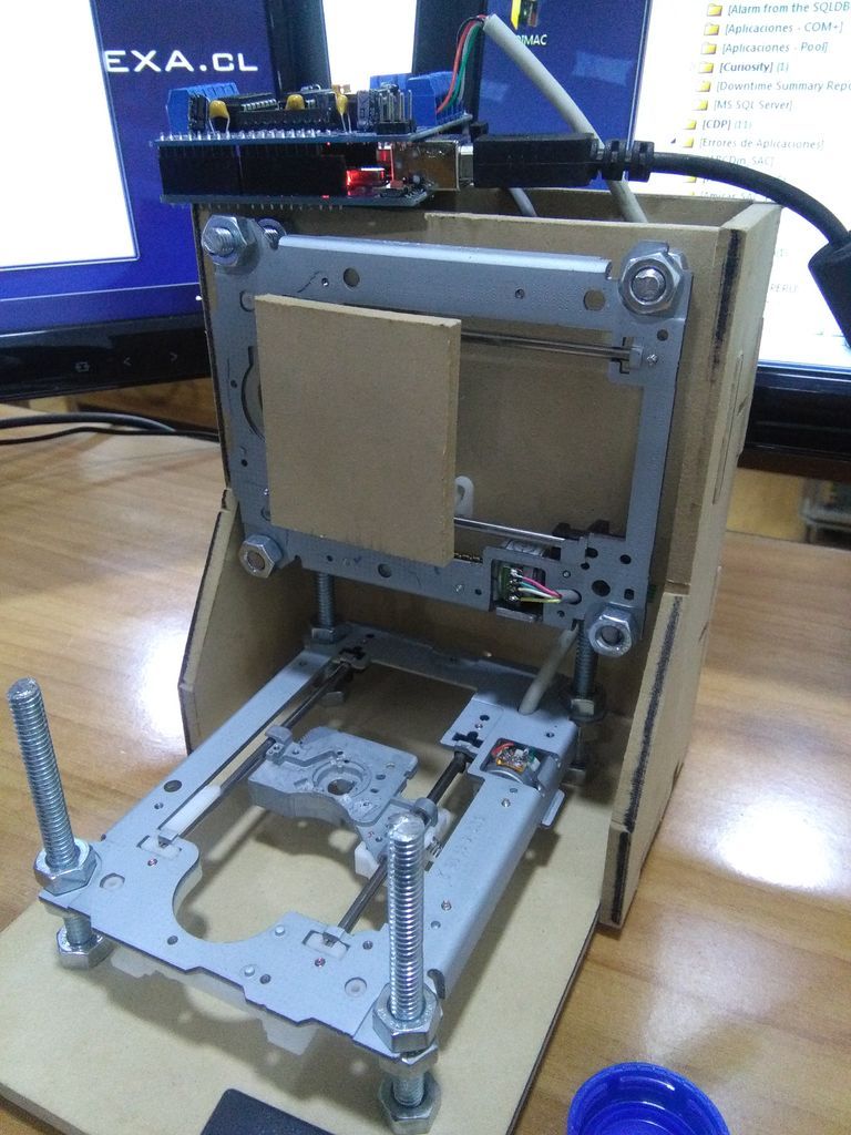 The result should look like this:
G28; ALWAYS FIRST AND FIRST! G0 F7200 Z50; obviously high lift of the drill M107; turn off fan G90; absolute positioning M82; Extruder in absolute mode M190 S30 ; Activate all used extruder M104 T0 S30 G92 E0 ; Reset extruder position ; Wait for all used extruders to reach temperature M109 T0 S30 M107 ;G10 F100 Y0; corr Y if necessary G0 F7200 Z50; obviously high lift of the drill G0 X38.100 Y43.180; first drilling point G1 F50 Z10.000; working feed of the drill G0 F7200 Z15.000; idle feed (rise) and start level ;Tool cutting feed for the next point G0 X38.100 Y38.100; next drilling point G1 F50 Z10.000 G0 F7200 Z15.000 G0 X38.100 Y33.020; next... G1 F50 Z10.000 G0 F7200 Z15.000 *** G0 X43.180 Y22.860 G1 F50 Z10.000 G0 F7200 Z15.000 G0Z50; drill lifting G0 F4800 X0 Y0; starting position M107; turn off fan ; Disable all extruder G9one ; relative positioning T0 G1 E-1 ; Reduce filament pressure M104 T0 S0 G90; absolute positioning G92 E0 ; Reset extruder position M140 S0 ; Disable heated bed M84; Turn steppers off
We save it with the .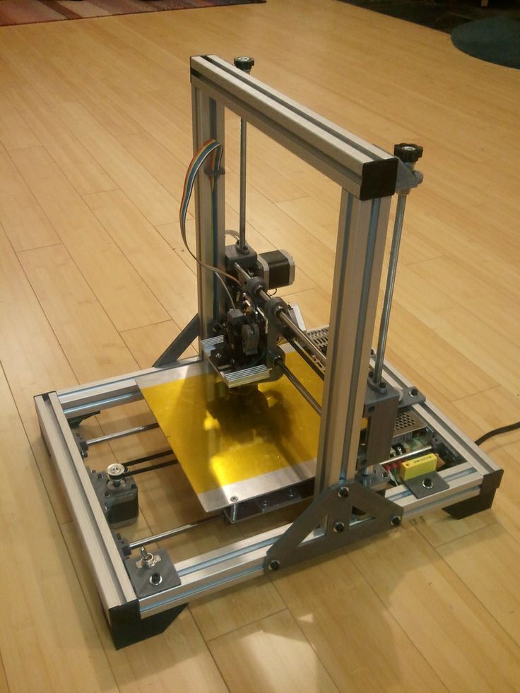 gcode extension, which can already be given to the printer for
execution after adjusting the initial position of the “X” axis with a steel stop by +100 mm as in the photo.
In the code "S30" - neutralization of the heating of the table and extruder, it will heat up to 30 Celsius. Further, I did not understand the code, perhaps there are safer options for the header. "Fxxxx" - execution speed, not indicated until the G-code is changed to another one.
Microdrill from DPR-52 with a diameter of 30 mm with a collet chuck, the holder is printed on the same machine. The holes of the holder are marked and drilled in place, along the holes where the nozzle of the hot end and the additional M4 screw for fastening the extruder enter. Its model for printing in the G-code is
To fix the DPR-52, a clerical clothespin is used, which is put on the lips of the collar holder obtained during printing.
Having wrapped the felt-tip pen with foamed polyethylene and inserted it into the holder, we look at how everything happens on paper. The letter was located exactly as in the Sprint, if you look at the printing table lying down. The origin of coordinates (“Origin of coordinates” - “Left corner (Top)”) in Sprint coincides with the origin of the 3D printer.
In the case of a real board on the scheme in Sprint, you need to put technological contacts - patches, on which you can align the board before fixing it on the table. For example, at the corners of a rectangular board, not forgetting the drill radius allowance. Naturally, these coordinates must be moved to the beginning of the drilling coordinates code, immediately after the header. Finding them is easy, set the finest grid in Sprint and using the Meter tool, the accuracy will be up to the second decimal place. Then search in Notepad++. Having reduced the speed to a convenient minimum, having determined the position of the board, we mark the position of 2 sides of the same corner with a pencil on the table. It is more convenient to mark the position of the near side and the left.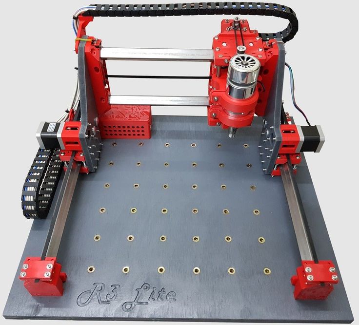 The board is attached with double-sided tape to the table. It is easy to peel it off, if you make an effort to wait a little, then there will be no gaps in thickness and you do not need to clean two surfaces, the board and the table.
To drill with a different diameter, you should find the commands T02 or T03, etc. in the import file. Txx, they mean a tool change (if you checked the “sort by diameter” checkbox during export). By setting the command G4 S180- we get a pause of 180 seconds, during which time we need to change the drill and set its level. A pause must be inserted at the drilling coordinates of the first point after the code for changing the drill and drilling a new (larger) diameter with the still previous drill. After replacing the drill, we drill manually and fix the microdrill in the desired position with a clothespin. The Txx change code must be deleted, leaving a mark for yourself.
You can split the entire file into drill files with different drill diameters.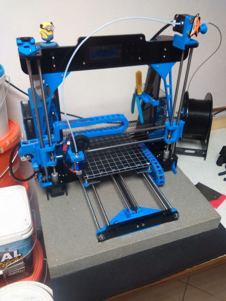 This requires the replacement of limit switches with reed switches or optical ones, since the regular ones are generally mounted on nylon ties and do this from one installation.
Naturally, this method requires a lot of refinement and operator involvement, but as a "take it out" solution it is more than suitable.
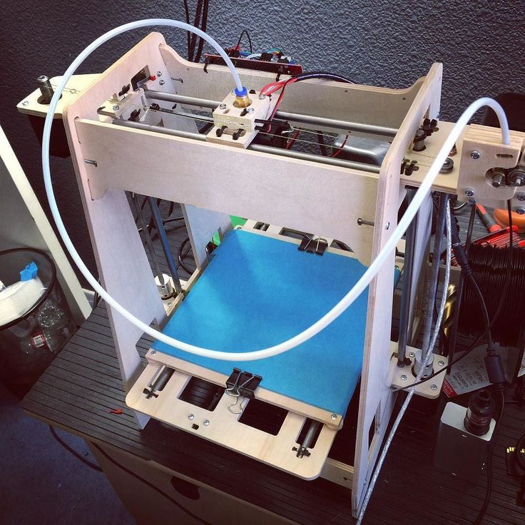
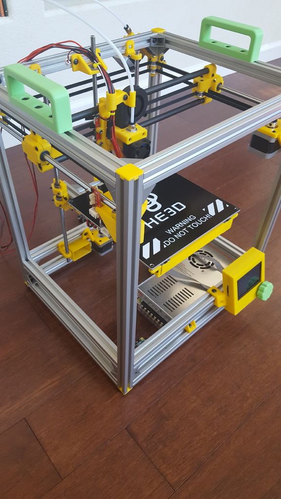
CNC 3D printer
Drawings of a CNC machine that can be printed on a 3D printer
Probably every owner of a 3D printer has thought more than once that: 3D printing is, of course, good, but it would also be cheaper to make a CNC router. Wood costs an order of magnitude less than plastic, and if the object being manufactured can be assembled from flat parts, then plywood cut on a CNC machine turns out to be almost waste material.
At the end of this article, you can download drawings of CNC machine parts and print them on a 3D printer. Also in the article there is a video of the assembly and operation of this router.
The CNC machine turns out to be very technological and easy to assemble, in fact, after printing, you will have a constructor that you just need to connect with nuts and screws.
If you collected constructors in childhood, then you can also handle the assembly of the CNC machine!
Despite the fact that the machine is assembled on parts printed from PLA, it is quite capable of working with the Makita RT0700C router - it is he who was photographed. You can also supply a budget spindle with Aliexpress ER1 500w, see links to electronics and spindle at the end of the article.
What you saw in the photos at the beginning of the article is a modified version of the CNC machine, with cable channels and connecting a vacuum cleaner. But initially the concept was much simpler and at the same time - it worked great!
Video of assembly and testing of the printed CNC machine
The video above shows the assembly of the CNC machine from parts printed on a 3D printer, as well as its test runs.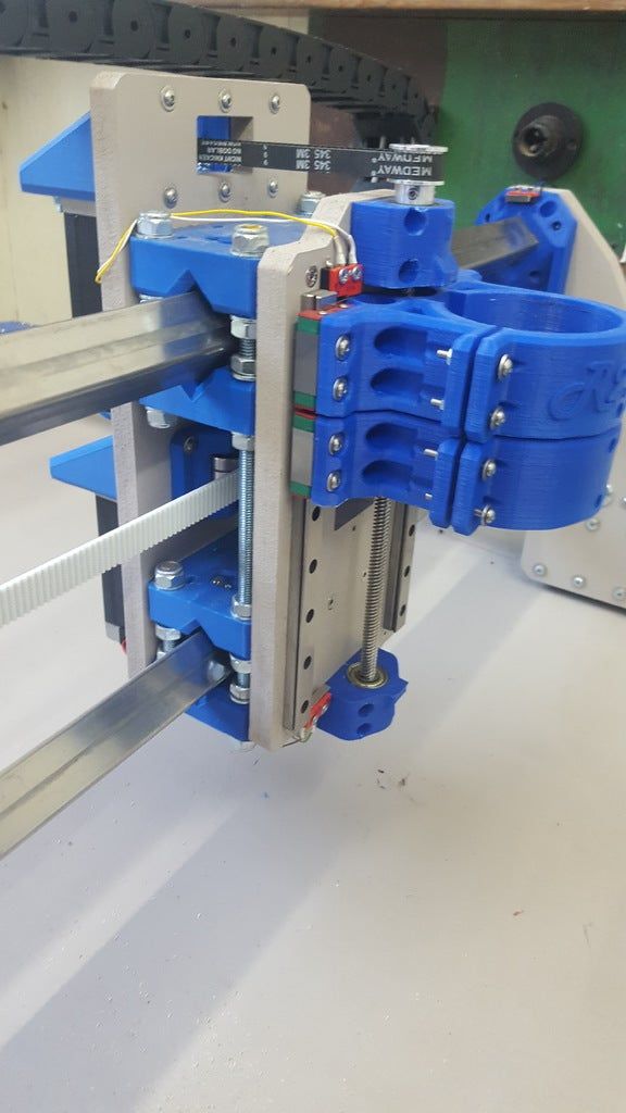 Printing is done with PLA plastic, it is quite strong in bending and has less shrinkage than ABS plastic. See below for a list of fittings and electronics for assembly.
As you can see, despite the apparent fragility of the design, the CNC router performs test tasks without problems. And if you need faster work with a large depth of the cutter, then with this machine you can cut a set of drawings of a durable plywood CNC machine.
Like any other do-it-yourself homemade product, this CNC machine printed on a 3D printer has undergone improvements. Cable channels and a nozzle for connecting a vacuum cleaner are not only beautiful, but also practical! Detail drawings can be found in the archive with the machine itself at the link at the end of the article.
The third video shows another refinement, this time an increase in the size of the working area.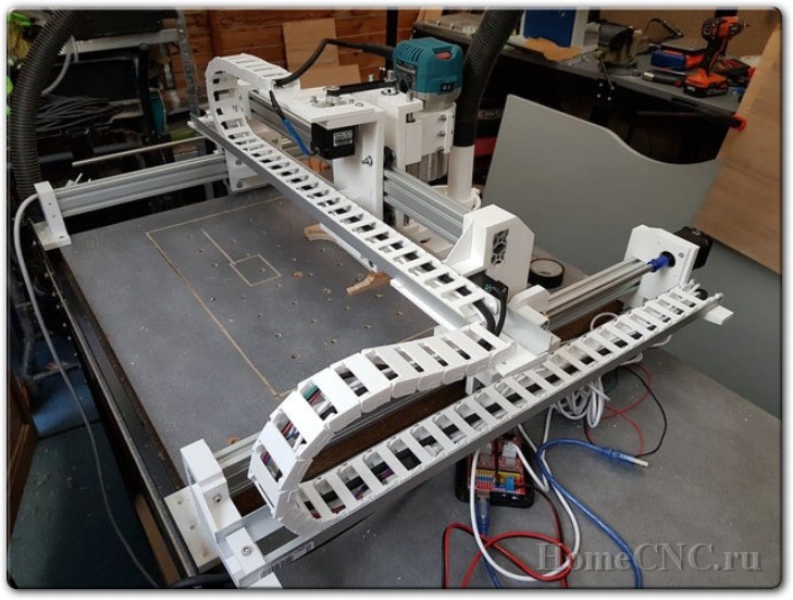 Fortunately, for such a refinement, it is enough just to change the profile to a longer one and put the corresponding lead screws, which in this case are made from an ordinary construction stud.
The whole alteration takes an hour, a maximum of two of your time. By the way, you can store the machine in disassembled form, assembly and disassembly takes only 10-15 minutes. If you only need the CNC machine from time to time, then you can save a lot of space in your home workshop by disassembling the CNC when you don't need it.
Accessories for assembling CNC machine
- 04x | Stepper motor Nema17
- 03x | Flange nut M5 / M8
- 04x | Aluminum profile 20x40 mm (see length according to your working area)
- 03x | Lead screw T8, with nut (100 mm shorter than aluminum profile)
- 14x | Nylon wheel with 5 mm bearing (type B in the link)
- 02x | Chrome steel rod 8 mm in diameter and 180 mm long (Z-axis)
- 01x | 200 mm lead screw T8, with nut (Z-axis)
- 04x | LM8UU linear bearing
- 03x | Standard 8mm bearing
- 01x | Pulley GT2 20 teeth, 5 mm inner diameter
- 01x | Pulley GT2 20 teeth, 8 mm bore
- 01x | Toothed belt GT2 200mm ~ 220mm
Screws and nuts (also take a nut and washer for each screw):
- 12x | M6 x 30 mm screw
- 04x | Screw M6 x 35mm, 35mm VERY important for attaching the spindle to the Zaxis cart
- 26x | M5 x 50 mm screw
- 22x | M4 x 15 mm screw
- 08x | M4 x 10 mm screw
- 16x | M3 x 15 mm screw
- 20x | Wood screw 4mm (fixing the CNC machine to the base)
- 30x | M4 clamp nut
CNC electronics
Arduino CNC Shield from Protoneer is used as control electronics, there will be a separate article about it soon.