Arm based 3d printer controller
The Top Robotic Arm 3D Printing Solutions
3D printing news News What Are the Robotic Arm 3D Printing Solutions on the Market?
Published on October 14, 2022 by Claire S.
One of the trends we have increasingly seen as additive manufacturing industrializes is an increased focus on large-format additive manufacturing. Though this can of course be achieved with large machines, notably those using FDM, robotic arms offer a number of advantages for users. Robotic arms allow not just for large-scale printing thanks to the long reach of the arms, but also more freedom thanks their multiple axes as well as the fact that the resulting parts often do not require support structures. Though there are only a handful of manufacturers who create the robotic arms, they have been adapted by 3D printing manufacturers for both polymer and metal AM solutions. In the following list, in no particular order, we take a closer look at what is currently on the market, both for original arms and adapted solutions.
Original Robotic Arms Manufacturers
KUKA
The German company KUKA is undoubtedly one of the leaders in the automation market, offering robots that enable the electronics, automotive and healthcare industries to simplify their manufacturing processes. KUKA develops solutions that can be adapted for additive manufacturing. It is therefore not surprising to find the KUKA brand on many robotic 3D printers, whether for designing metal, plastic or even concrete parts. One example is the KR QUANTEC line of robotic arms, which offers machines with a reach of 2,671 to 3,904 mm and a load capacity of 120 to 300 kilos.
The KR QUANTEC arm was equipped with a nozzle to extrude concrete for the Besix3D company (photo credits: KUKA)
ABB
ABB group is a multinational company which produces robotic arms, including those used for 3D printing. Their robotics portfolio is diverse with different types of industrial robots to fulfil consumer needs.Their RobotStudio® programme is the world’s most popular offline programming and simulation tool for robotic applications.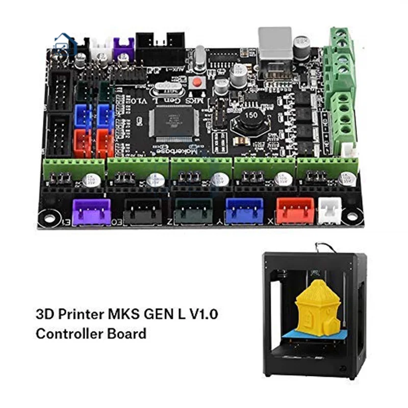 According to the company, with its solution, users can unlock flexibility and upgrade their business productivity to the next level. They are even able to design robots to suit their own unique needs, notably in additive manufacturing. As you will see further down the list, ABB six axis industrial robot is used by Massive Dimension, a company which works on sustainable development in the 3D printing industry.
Massive Dimension and ABB Additive Manufacturing Demonstration at IMTS 2022. (Photo credit: Massive Dimension)
Comau
Comau is an Italian industrial automation and robotics company. The company develops systems, products and services compatible with Industry 4.0. In particular, its portfolio includes a complete family of robots, including robotic arm solutions. Since 1978, Comau has been manufacturing these machines with the aim of integrating and improving innovative applications in all industrial sectors. There are several robotic arms, and they differ in their payload capacities.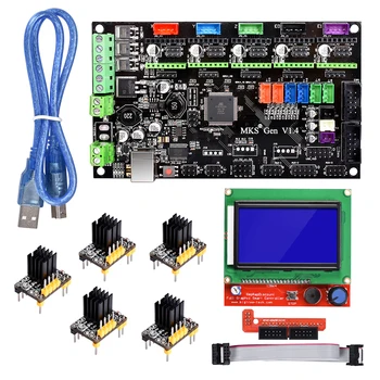 Still, they leverage IoT and AI technology to operate autonomously.
Third Party 3D Printing Companies Using These Solutions
CEAD
CEAD is a Dutch company based in Delf that develops large-scale 3D printers. This company stands out as it offers robot-based solutions that combine printing and CNC milling processes in one process. Another solution is the AM Flexbot, a robot-based solution for large-scale 3D printing. Siemens Sinumerik controllers are responsible for controlling the Comau robot arm, thus not requiring any robot controller. This controller can control 31 axes at the same time as it moves along its path. Your AM Flexbot can be expanded with additional functions such as a rotary table, additional robots, or other production processes such as CNC milling. It is the perfect choice for a customized solution with a specific application.
DXR Series from Weber Additive
German company Weber Additive, dedicated to the development of different manufacturing technologies, also has robotic arm solutions for 3D printing.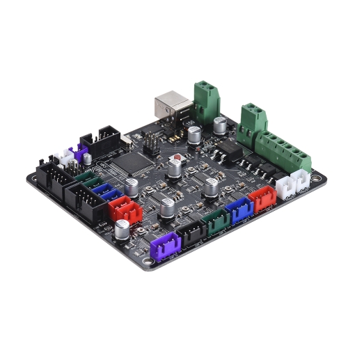 Weber’s DXR robotic system features a high-quality extruder capable of 3D printing. The extruder is powered by a 6-axis industrial robot that allows it to move precisely. Its robotic arm based on the manufacturer Kuka and its AE series extruders are adapted to the needs of its customers to provide the most optimal results. These systems offer great advantages, such as 3D printing with 6-axis kinematics, a variable angle of the manufacturing head or overprinting on existing parts, among others. You can take a look at the solution in the video below:
The robotic arm from Hyperion Robotics
Founded in 2019 in Helsinki, Hyperion Robotics is a company specializing in the construction industry. It uses additive manufacturing to design more affordable structures, wanting to make the market more sustainable and most importantly, more automated. To do this, it relies on KUKA robots on which it mounts an extruder capable of depositing Hyperion Robotics’ material. This is a special concrete mix that uses a reduced amount of cement thanks to recycled waste components. It also designed its own software that allows it to work with any robot. In terms of applications, the Finnish company has already built decorative elements, structures imitating coral reefs and energy infrastructures.
Photo credits: Hyperion Robotics
Massive Dimension
Massive Dimension, as their name undoubtedly suggests, is a manufacturer of large format 3D extruders and full solutions, including turnkey robotic printing cells. Specifically, the company was founded with the goal of contributing to sustainable solutions in order to reduce waste on the planet. Currently, Massive Dimension’s solutions are centered around polymer pellet 3D printing. For their robotic cells, they include six-axis industrial robotic arms from ABB. When combined with the ABB 3D Printing Powerpac software, users have access to a comprehensible workflow for pellet 3D printing.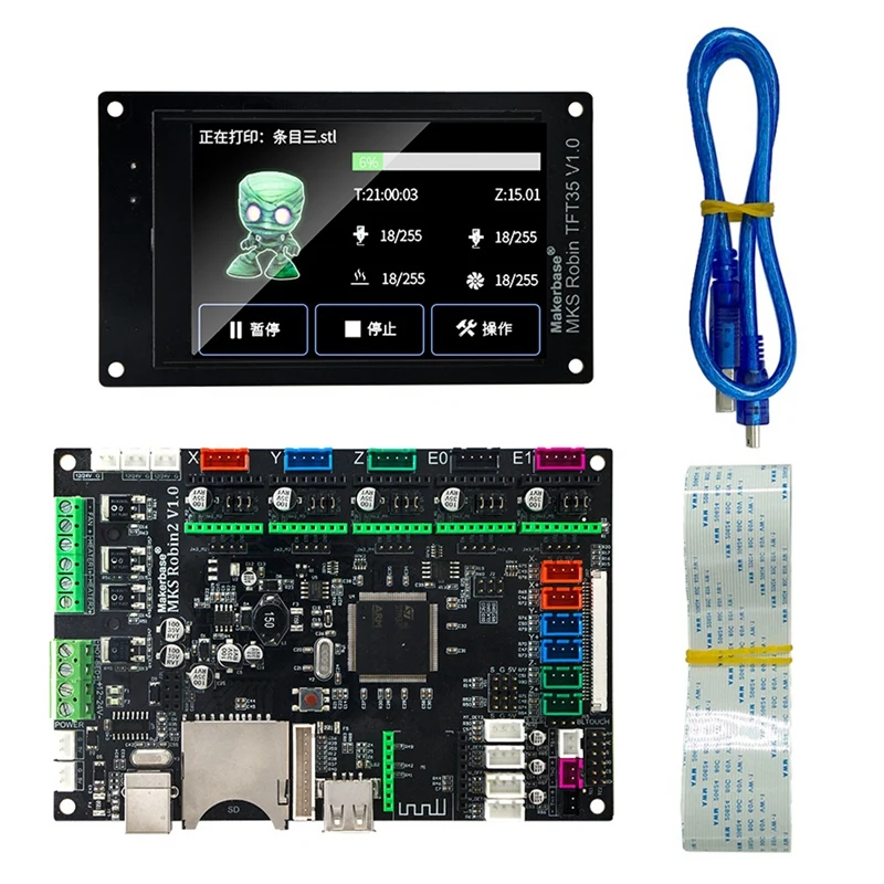 The company notes that their robotic arms have been custom-tailored for robotic printing, including large format printing thanks to a build volume of 3ft x 5ft x 5ft. Moreover, these cells can also be further customized to fit each user’s individual needs.
Massive Dimension
Orbital CompositesOrbital Composites aims to disrupt the 3D printing industry. They believe that robotics is the answer to the limitations faced by the industry, such as scale, speed, strength and design. Their Orbital S, the first robotic 3D printer built for industrial scale, was released to tackle these problems. The impressive robot has a maximum speed of 2m/s, has a maximum payload of 10kg and a maximum reach of 1.1m. The build platform is 1m x 1m x 1m, giving the ability to create relatively large end use parts. Furthermore, the user has a choice of materials. It uses the Kuka KR10 R1100 robot arm; Kuka is an official partner of the company.
Orbital Composites’ Orbital S robotic 3D printer.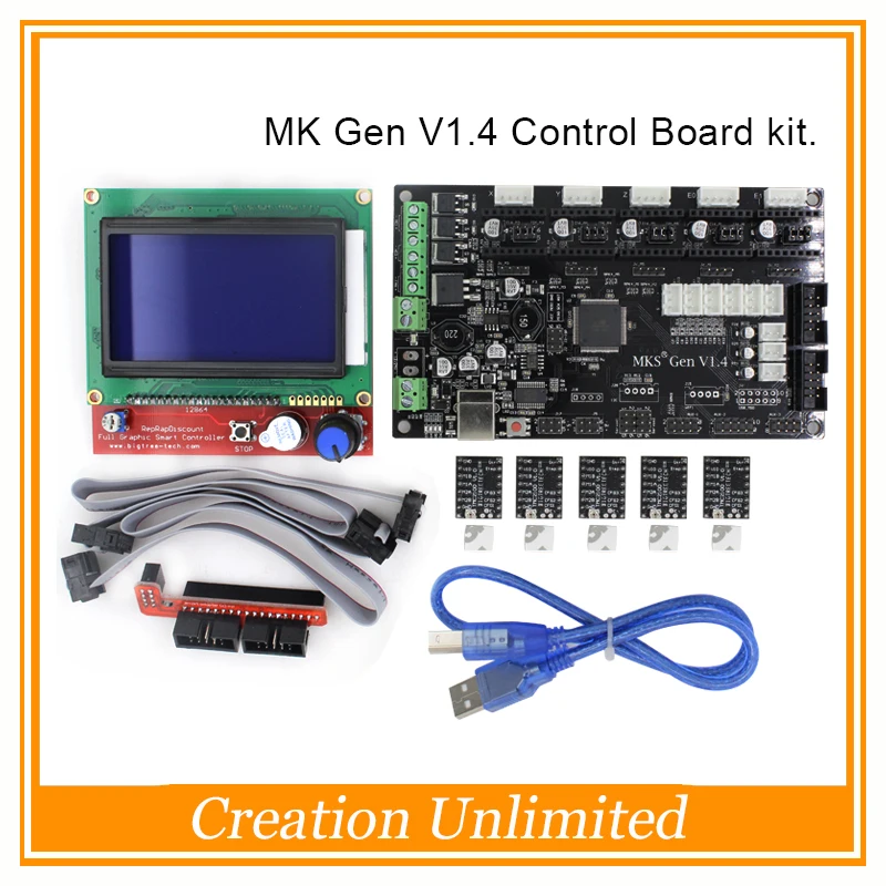 Photo Credit: Orbital Composites
Dyze Design et Pulsar
Pulsar is a state-of-the-art, large-scale, high-speed plastic pellet extruder. It was designed with one goal in mind: to 3D print large parts as quickly and inexpensively as possible. Pulsar is compatible with robotic arms for 3D printing and is capable of producing up to 500 mm3/s (2.5 kg/h) of material. It can also be used with large nozzles from 1.00 mm to 5.00 mm. Finally, Pulsar is ready for all environmental conditions. The water cooling loop ensures that the entire system is at a constant temperature. With an additional heat shield, Pulsar can withstand a 200°C environment. This makes the machine compatible with plastic materials such as PEEK, Ultem and PSU.
Branch Technology
This company combines additive manufacturing, prefabrication and digital technology on a large scale. Thanks to their patented technology, it allows the team of designers and architects to imagine, compose and finally build those structures that were previously impossible with traditional construction methods. One example of a project they have carried out is in the construction of a 3D printed pavilion in which they have used KUKA robotic technology. The combination of robots with 3D printing has enabled the architects and designers from Gould Turnes Group with whom they have collaborated to not only tackle the construction of the final structure but the design process from start to finish. The 3D printing process applied to the KUKA robots is a great combination as it allows the production of precise, lightweight and cost-effective components from a variety of materials.
At this point, if you are interested in WAAM technology, you have almost certainly heard of MX3D. The Dutch company made waves for its creation of an entirely 3D printed, metal bridge which is currently located in the center of Amsterdam.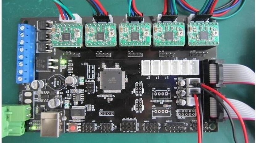 This among other large-scale metal 3D printing feats has made them a popular choice in many sectors. And the company uses robotic arms for its solutions. More specifically, MX3D uses an 8-axis ABB industrial robotics system in its M1 metal AM system, allowing for the creation of medium to large-scale metal parts. To ease the process, the company also offers MetalXL, a software that controls their WAAM-based systems, ensuring that the part is manufactured as intended, controlling everything from design through monitoring during the actual printing.
mx3D printer
Continuous CompositesContinuous Composites was recently selected by NASA to produce low coefficient of thermal expansion (CTE) open isogrid composite structures for space applications, using its patented Continuous Fiber 3D Printing (CF3D) technology. This printer combines high performing composite materials with rapid curing thermoset resins. They say that this will demonstrate the printer’s capability to produce high quality and consistent printing, with excellent accuracy and precision. The printer is configurable and scalable and therefore can be applied to projects of various dimensions. They turned to Comau for their robotic arm needs.
A robotic 3D printer with Comau arm capable of producing thermoset objects with continuous carbon fiber (Photo credit: Continuous Composites)
What do you think of this listing? Have we missed any? Let us know in a comment below or on our LinkedIn, Facebook, and Twitter pages! Don’t forget to sign up for our free weekly Newsletter here, the latest 3D printing news straight to your inbox! You can also find all our videos on our YouTube channel.
Robot-Based Large Scale 3D Printing Solutions
Skip to contentRobot based solutions large scale 3D printingadmin2023-02-22T14:00:30+00:00
A large scale 3D printing solution using robotic arms where multiple processes such as printing and milling can be combined into one cell
Download brochure
The AM flexbot is a flexible robot based solution for large scale additive manufacturing. This versatile system provides lots of options which can be integrated to configure the system to your specific needs. This system has proven itself to be the go to system for large scale 3D printing implementations in the industry. The system is delivered and installed worldwide.
Download brochure
Features
- CEAD Pellet Extrusion technology
- Comau robot
- Siemens Sinumerik 840D
- Working table(s)
- Safety caging
- Pedestal for robotic arm
- Dryer
Modular System
The AM Flexbot is ideal for custom solutions to fit a specific application. Siemens Sinumerik is used to directly control the Comau robot arm, meaning no robot controller is needed. This enables very accurate operation of the robot, especially in terms of position accuracy while travelling along a path. The Siemens Sinumerik can control 31 axes. Therefore your AM Flexbot can be easily extended with additional functions such as a rotary table, additional robots or other production processes such as CNC milling but also other processes.
Printing and Milling
The AM Flexbot offers the unique option to combine 3D printing and milling into one automated process. For mold making and tooling applications ideal to achieve the required surface finish. For end use parts the CNC milling functionality can ensure high tolerance mounting flanges and holes.
AM Flexbot additional options
- CNC Milling upgrade
- Robotic arm with payload up to 290 kg
- Heated working table
- Larger working tables
- Larger extruder for higher throughput up to 84 kg/hr
- Lineair track for large work volume
- Dynamic flow control
- Rotary table for complex shapes
Services
In most cases, we start off with a Pilot Project. This means we’ll investigate important aspects such as your design, the required material needed for your application and the print strategy.
Learn more
Technology components
Stand alone extruder systems, lightweight and ideal for mounting on existing systems such as robots and CNC equipment. Used by integrators and clients for their specific applications.
learn more
Gantry based solutions
Ideal for efficient production of large parts or multiple parts in one production run. Complete turn key machines, ready to start printing your parts immediately.
learn more
Page load link Go to TopWe assemble a 3D printer with our own hands. Step-by-step instruction. Part 4.
Friends, hello!
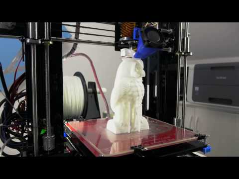
At the end of today's part, our printer will be printing.
Let me remind you what we have already done:
1. Introductory. Purchasing everything you need. 2. Assembling the printer. Part one. Body and mechanics. 3. Assembling the printer. Part two. Electronics. 3.1. Additional photos.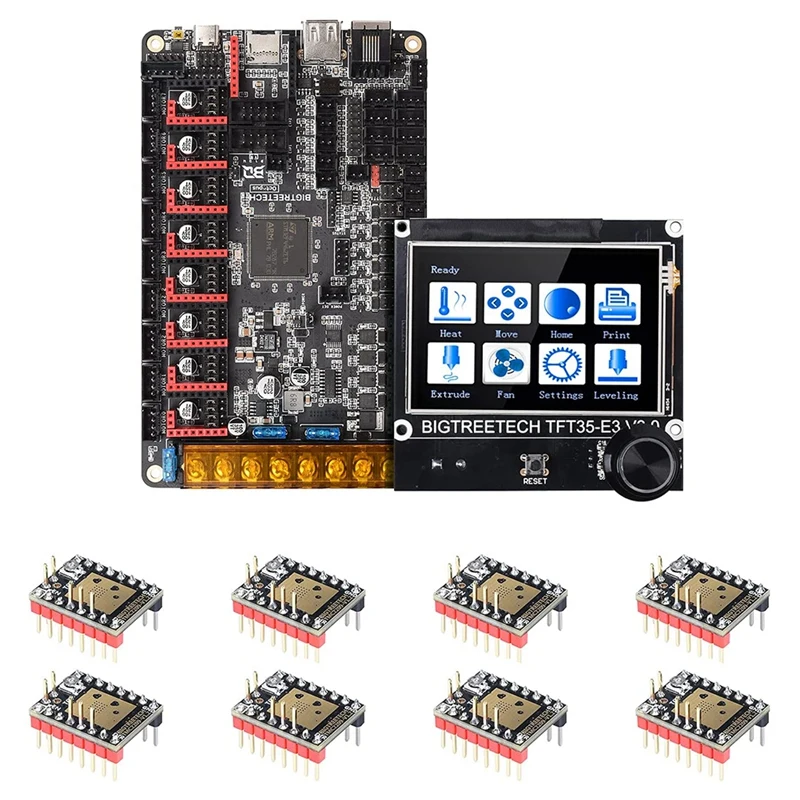 3.2. Connecting the electronics 4. Firmware and printer setup - Marlin.
5. Firmware and printer setup - Repetier-Firmware.
Today we need a multimeter, a computer, the USB cable that came with the Arduino Mega, an SD memory card.
I warn you right away, before plugging this whole thing into a socket, check whether everything is connected correctly 7 times, and when working with a multimeter, one awkward movement and Arduino to replace. I have already killed 3 Arduino Mega, including one when setting up this printer, and so that you do not have to wait another two weeks for this post, I quickly found a new 'dunya' on Avito. If in any doubt, double-check or ask again! If I warned.
First things to check:
1. Position of the drivers.
2. Correct connection of limit switches.
3. Polarity of all wires.
4. General wiring diagram for all electronics.
Have you checked? 7 times? Let's go further:
Turn on our printer, turn on the switch (on the power cable connector with a fuse and do not forget to install the fuse), it should turn on:
1. The fan on the power supply.
2. RAMPS blower.
3. Print head heatsink airflow.
4. Screen backlight.
5. Printer backlight, can be turned on or off with the switch.
Working?
No - go to the previous chapters.
Yes, let's move on.
I took a picture from my neighbors:
Using a multimeter, we measure the voltage (DC Volts - V). By the way, just at that moment my hand trembled, and I first soldered the stabilizer, which is most often on fire in this situation, then I realized that not only the stabilizer had burned down, I went for the 'dunya'. On A49 drivers88 can be handled without a multimeter, just by the sound, but we follow the rules, set the voltage to 0.68V on all drivers, for A4988 you can up to 1V.
Ready?
Let's go further:
Download here - Arduino Software, strange things have been happening with this program lately, I have version 1.6.5, my colleagues have other versions.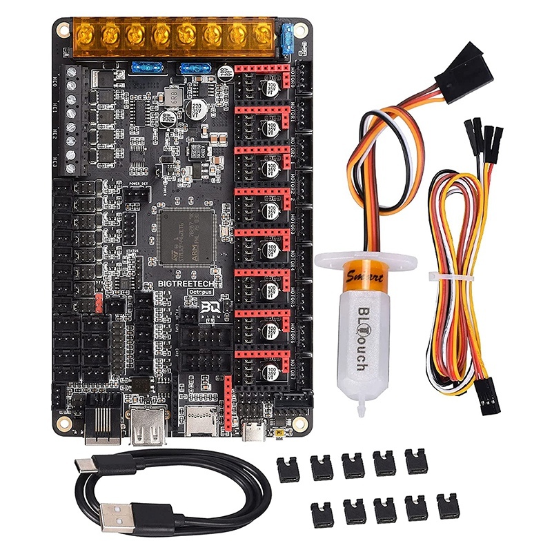 Install on your computer.
most likely we have a 'dunya' not a 'dunya' at all, but a Chinese clone on the Ch441 chip, then we also download the driver, for example here - install it on your computer.
Download the firmware - Marlin - unpack the archive with the firmware to a convenient place.
Downloading the library - u8glib - do not unpack the archive.
We connect the printer to the computer via a USB cable, the drivers are installed and as a result you should see the following picture in the device manager of your computer:
Remembers the number of the COM port on which your Arduino board is installed.
Open the file ...Marlin-RCMarlinMarlin.ino (in Windows Explorer it can be just Marlin without extension) using Arduino Software:
Next go: Tools - Board:... - Choose your Arduino/Genuino Mega or Mega 2560 board.
Next: Tools - Processor:. .. - ATmega2560(Mega 2560).
Next: Tools - Port: ... - We select the same COM port that we remembered in the device manager of our computer.
Going further - open the Configuration.h tab:
All basic settings will be made in this tab.
We need to add a library to work with our screen - u8glib, we have already downloaded it, then we need to add it to our firmware.
Go Sketch - Include Library (Add Library) - Add .ZIP Library...
In the window that opens, look for your archive with the u8glib library, select it and click open.
Next Sketch - Include Library (Add library) - at the very bottom we see u8glib appeared, select it.
A line appeared in our sketch:
#include Starting the firmware configuration:
1. You need to select the controller of our printer, for this we go to the boards. h tab
h tab
We see a huge list of controllers with which the Marlin firmware can already work:
Let me remind you that we use Arduino Mega 2560 + RAMPS v 1.4 and we have a heating table, controlled blowing of the part and one print head. I think everyone has already found our board:
#define BOARD_RAMPS_14_EFB 43 // RAMPS 1.4 (Power outputs: Hotend, Fan, Bed)
Return to the Configuration.h tab line:
2. Setting the table temperature sensor.
Most likely you, just like I have a regular Chinese 100K thermistor, in this firmware it is denoted by the number 1:
// 1 is 100k thermistor - best choice for EPCOS 100k (4.7k pullup) hotend and for the table:
We can leave the maximum and minimum temperatures unchanged or adjust to our needs:
3. PID settings - I recommend doing it after you have printed on your printer for several hours.
This is done as follows, in the Pronterface program, you need to connect to the printer
and give the command
Where M303 is the calibration command, E0 is the hot end, C10 is the number of heating-cooling cycles, S260 is the typical temperature of the nozzle.
The printer runs the hotend heating 10 times, after that it outputs the values Kp, Ki, Kd. We write these values into these firmware:
The same for the table, only the command:
M303 E-1 C10 S110
Where E-1 is the table, S110 is the typical table heating temperature.
Due to prolonged table heating, a timeout error may occur, just restart the command.
Enter the obtained values into the firmware:
4. Set up the operation of the limit switches:
Let me remind you that in our case we use:
//)/uncomment the corresponding lines:
And also change the direction of the location of the 'house' in accordance with the position of the trailers:
4. Print field size settings.
In my case, it turned out exactly 200*200*190 mm:
Your values may differ slightly, literally mm, but this is established empirically later.
5. Setting the speed of moving home:
Set empirically, while leaving the default.
6. Setting the movement steps along the axes.
We need to find out how many steps our printer takes per unit of distance (in our case 1 mm) along each of the axes.
In our case, we use a motor that takes 200 steps per revolution, and we break this step into 16 microsteps.
Further along the X and Y axes we have a belt drive with a pitch of 2 mm for each tooth and a spool with 20 teeth.
Thus, our engine makes 200 * 16 = 3200 steps in one revolution and overcomes the distance 20 * 2 = 40 mm in these 3200 steps.
Therefore, in order for the printer to move 1 mm, it takes 3200/40 = 80 steps (this value is the same for the X axis and the Y axis).
A trapezoidal screw is installed on the Z axis, which has a different pitch, who purchased which one. For example, 8 mm per full turn, i.e. our printer travels 8 mm in one turn of the screw along the Z axis and does the same 3,200 for this, although to accelerate the Z axis, you can set crushing (with jumpers) and 1/8, how to do this is written in 3 parts.
So, on the Z axis, in order to move 1 mm, the printer needs to make 3,200/8 = 400 steps.
Extruder feed. In order to understand how much our extruder feeds plastic, we need to calculate the circumference, from the school geometry course, remember that the circumference is 2 * 'number pi' * radius of the circle or 'number pi' * diameter of the circle. Now we don’t need special accuracy (we will adjust it more precisely later), the diameter is approximately 5.8 mm, therefore, in 3200 steps or one revolution, our extruder delivers 3.1415 * 5.8 = 18.2207 mm of the bar, and for the feed of one mm he needs 3,200 / 18. 2207 = 175.624 steps, rounding up to the whole step 176.
We write the obtained values into the firmware:
Here, in order X, Y, Z, extruder.
7. Setting speeds and accelerations:
leave these parameters unchanged for now and will adjust them in a more precise setting:
8. Setting the screen:
Uncomment (remove the double slash //) from the lines
#define ULTRA_LCD
#define DOGLCD
#define SDSUPPORT
#define ULTIPANEL
#define REPRAP_DISCOUNT_FULL_GRAPHIC_SMART_CONTROLLER
9. You can name your printer after yourself, for example 'Plastmaska'
To do this, uncomment the line:
//#define CUSTOM_MACHINE_NAME 'Plastmaska'
All basic firmware settings are done, check by pressing the 'Check' button :
And download by pressing the 'Load' button:
After that, our printer will reboot and show you various parameters.
Now we need to fine-tune the printer:
1. the correct direction of movement along the axes.
Should be:
X-axis - left 0 (or minus), right 200 (or plus)
Y-axis - towards you 0 (or minus), away from you 200 (or plus)
Z-axis - up 0 (or minus), down 190 (or plus)
extruder - feeds plastic is plus, rolls plastic is minus
If everything matches, move on, if not, then change the parameters, change the parameter true to false or false to true - parameter changes only where it is needed (where movement along the axis is incorrect):
#define INVERT_X_DIR false
#define INVERT_Y_DIR true
#define INVERT_Z_DIR false
#define INVERT_E0_DIR false
compile and re-upload the firmware, check, match.
2. Limit switches operation:
Place the carriage and table in such a way that the limit switches are not pressed.
Command M119 via the Pronterface program.
We see something like this:
or so
should be correct:
or
x_min: open
y_max: open
z_max: open
This is only for normally closed contacts, if you use normally open, then you should have the opposite, the limit switch did not work - open, the limit switch worked - TRIGGERED.
If something is wrong here, then most likely they made a mistake in the previous setting of the limit switches or in their connection. go back and check.
3. Proper travel home.
We send a command to the printer to go home, it is possible through the printer menu, it is possible through the programs on the computer.
The carriage should move to the left and away from you, the table should move down.
Is everything correct? moving on. No? we return to the firmware
4. We select the dimensions of the movement:
here everything is empirically and with a ruler we select the parameters for all axes and enter them into the firmware:
5. Checking the bar feed:
We take a line, measure 10-20-30 cm bar, mark and give the printer a command to squeeze out 10-20-30 cm of the bar, check how accurately he did it, based on the values we correct the firmware.
6. Selection of speeds and accelerations:
No one will tell you better than Sergey Taranenko:
We enter the obtained parameters into the firmware, fill it in the printer, check it.
7. Setting the gap between table and nozzle.
The table must first be coated for good adhesion to the table, I personally use a glue stick (3M Scotch, UHU, Kalyaka-Malyaka). I put glue on cold, clean, dry glass, after that you can heat the table, one of these days I plan to try glass-ceramic glass, nothing works from a pencil that has been tested better.
We heat up the table and the nozzle to the operating temperature (110/250) send the table to point 0, then three points further (where we have the adjusting screws)
Adjust the distance with nuts so that a sheet of paper is pressed between the nozzle and the table nozzle to the table, but at the same time it could be pulled out without tearing, it is necessary to achieve this so that there is such a distance at any point of the printer, for this it is enough to align the table 2 times at 3 points.
Some of the parameters can be changed via EEPROM, this can be done either in the Repetier-Host 9 program0003
Or via commands in the same Pronterface.
That's all, I'm waiting for your questions, on the basis of which I want to make a certain FAQ on the printer.
Also the last chapter '5. Firmware and printer setup - Repetier-Firmware.' is postponed indefinitely, because the printer on which it was planned to install this firmware suddenly received MKS Sbase, and that's another story.
Finally, another video of how the printer prints:
and this is what happened:
Another well-known model, but of higher quality and better material:
Well, the new owners of the printer are happy.
Inspected:
Adhesive coating applied:
We set to work:
What I plan to do next, the first thing is to complete the project with a double-headed printer:
But in the near future I want to make a plywood Ultimaker Go, I really liked the idea of wearing takeaway:
It is possible that Repetier-Firmware also sells there.
I also think in the direction of mixing colors during printing, in order to achieve this, but not with a gradient bar, but by mixing colors during printing:
How interested you were in following these projects, please unsubscribe in the comments.
Update
Part 5. Updates and additions. >> http://3dtoday.ru/blogs/plastmaska/small-update-ultimaker/ Please support this project in social networks. Article repost needed!
Just in case, I'm in touch.
90,000 3D Maternal Plant based on STM32F401CCU6 BlackPillReprap
Sign up for
Subscribe
I do not want
62
Good day to everyone who went to the light.
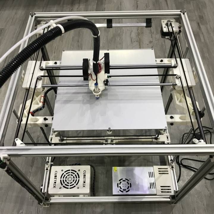
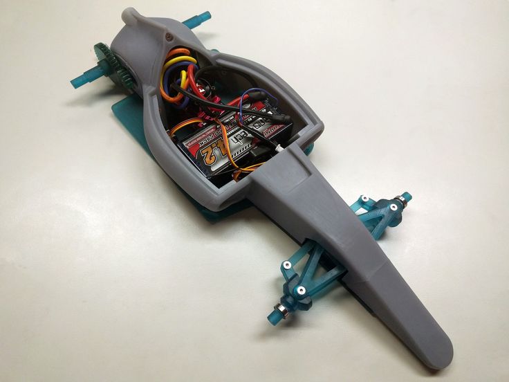
I would like to share with you a short review of my experience in creating your own printer motherboard based on the STM32F401CCU6 MK, commonly known as BlackPill.
I'll start with why:
- I was just curious to try something new. It would be possible to buy a 32-bit board instead of your old RAMPS, if not for excessive enthusiasm, as well as the desire to have everything you need and nothing more.
- no, but there is an economic component - the fee was not so expensive, the skill for change was pumped a little. And seeing the current prices for a set of Atmega2560 + RAMPS for the sake of outdated 8 bits, we can say that it turned out to be a plus.
So, what is the board like: this is the ideal of a minimalist in terms of capabilities - only 3 axes + extruder, 4 PWM controlled outputs: a table (with a powerful reliable field worker), a hot end, a model blower fan, an extruder blower fan (like me this was not enough before, the hotend cooled down to 50, the fan turned off and did not wind dust on itself all night), two temperature sensor inputs: for the table and for the hotend, respectively, 3 limit switch inputs, connectors to get 3.3, 5, 12 volts from the board. Powered by 24V. The inputs of the limit switches are protected by an optocoupler, the inputs of thermistors by suppressors, the USB input by a static protection microcircuit. I tried to make everything as compact as possible, but to fit into 2 layers (for those who want to repeat with LUT, photoresist or on a router), therefore 0805.
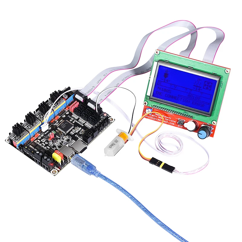
The firmware is built on the basis of Marlin 2.1.1 for self-assembled Core-XY in VisualStudio Code + PlatformIO. The board itself is added to Marlin under the name BOARD_STM32F401CCU6 , compile with environment env:blackpill_f401cc_env. EEPROM emulated in controller flash area, screen 2004 (RepRapDiscount Smart Controller) tested and working.
The board is already working successfully in the printer, but alas, there is no time to drive too much, again it is field work. However, I managed to test a couple of night seals, there are no complaints about the board.
GITAt the link to the github, those who wish will find all the sources: gerber files, a BOM list with approximate prices and links to all components, firmware, instructions for adding their board to Marlin (for those who want to assemble from the original sources themselves), instructions for adding its own thermistors (the board has a feature - a pull-up on the analog input of the ADC 1kOhm instead of the usual 4.7kOhm, this gives more ADC readings per degree at high temperatures).
P.S. Please share your experiences in the field of Open Hardware, together we can do something worthwhile.