3D printing multiple parts
Can You 3D Print Multiple Objects at Once? A How to – 3D Printerly
People wonder whether it’s possible to 3D print multiple objects at the same time on a 3D printer, so I decided to write this article to answer this question to let people know the answers behind it.
Can You 3D Print Multiple Parts/Objects at Once?
Yes, you can 3D print multiple parts or objects are once simply by placing more than one object in your slicer build plate, and slicing the models as normal. You can choose to 3D print one object at a time, or 3D print each layer of both objects simultaneously, which is the default.
Many people choose to 3D print single objects at a time, but it’s definitely possible to 3D print multiple parts. It can be safer to 3D print singular objects in case on of them fails.
I’d usually recommend for beginners to 3D print one object at a time until they have more confidence that they can get successful models to adhere to the build plate nicely.
It’s possible to duplicate models on the build plate in Cura, just by right-clicking your object and selecting “Multiply Selected” or clicking the object and pressing CTRL + M.
You can choose the number of copies to make.
Then you can rearrange where the models are on the build plate.
In most cases, you’ll be 3D printing objects layer-by-layer, so they will both be 3D printed at the same time. There’s also another technique where you can 3D print objects one at a time, also called sequential printing.
It can be useful in some cases, while it can also cause issues of one part coming loose and failing, causing potential failure to the other part. 3D printing smaller objects one at a time can be beneficial for better quality because it has more time to cool down.
How to Use Sequential Printing in Cura
To 3D print models one at a time, also known in Cura as sequential printing, you simply have to set your Print Sequence setting to “One at a Time”. This will print one model in its entirety before printing the next model. You may have to adjust your 3D printer’s build plate size in Machine Settings to bypass an error.
Here are the steps to use sequential printing in Cura:
- Find the Print Sequence setting in Cura under Special Modes, or by searching for “Print Sequence”.
- Select the arrow to open up the options and click “One at a Time”.
- You can then proceed to slice
- There may be an error with the build volume height being shorter. To fix this, simply go into Machine Settings by pressing CTRL + K, go to the “Printers” tab, then “Machine Settings” and simply edit your Z-height +1 (from 250 to 251 for example) and it should bring back the usual height and allow you to slice the model.
You can also get to the setting by going to: Preferences > Configure Cura > Printers > Machine Settings > then change the Z (Height).
The first model you add to the build plate should be the first model 3D printed with the sequential printing option turned on. You can choose which model to 3D print first by simply deleting the objects in a certain order, then hitting CTRL + Z to undo and re-add those deleted objects.
If you have two objects on the build plate, the first one you delete should be the first one to print, and vice versa.
With the two models below, to 3D print the model on the right first, you should delete the model on the right, then the left. After you undo this action, the model on the right should print first as shown in the “Preview”.
Adjust the slider on the right to see the view of a layer number to see which model prints first.
If the objects are too close or they intersect each other, the slicer will not be able to slice the prints when you click on the slice.
Check out the video below by CHEP showing how this all works.
How to Use Sequential Printing in PrusaSlicer
To use sequential printing in PrusaSlicer, simply go to the “Print Settings” tab, ensuring you are in “Expert Mode”. Go to “Output Options” and you’ll see a setting called “Complete individual objects”. Check the box and this will enable sequential printing, or printing one object at a time.
You can also set extruder clearance here.
You can duplicate any model on the build plate by right-clicking the object and selecting “Set number of instances…” then inputting how many models you want to add.
If the objects on the build plate are too close, you’ll be unable to slice them and you’ll get an error message saying the objects are too close and that the extruder will collide with them.
If you get this error message, you should space out the objects more, according to your extruder clearance.
After you space them out correctly, the “slice now” option will appear and you’ll be able to slice out the objects. Check out the video below that shows a user creating a specific order for the objects to print in.
You use the ‘E’ key to see the order of objects in 3D view before slicing. If you want to change the order, you can drag and drop models in the “Object List”.
Just like in Cura, the last model will be printed first while the first model will be printed last so you want to keep this in mind when adding the objects.
Can You Stack 3D Prints? 3D Printing Onto Another Object
Yes, you can stack 3D prints by placing them on top of another within your slicer. Many users have done this with facemasks and other basic models, though it could get complex with more detailed models. You can save a lot of time and space within your 3D printer by doing this.
It’s a good idea to leave a small space between the objects you are stacking so they can be separated after printing, as well as to maintain a smooth surface on both the objects.
In the case of face shields, users made sure to have a gap spacing close or equal to their layer heights, or in multiples of it. For example, if you are printing at a 0.2mm layer height, try to have a gap spacing of 0.2mm or 0.4mm.
How to Stack 3D Prints & Print on Top of Another Print – Cura
To stack 3D prints on top of another print, you first have to disable two key settings in the “General” section of the Cura settings. Disable “Ensure Models are Kept Apart” & “Automatically Drop Models to the Build Plate”. You can now import your objects or duplicate an object, and move one on top of another.
Simply use the “Move” function in your slicer and move the object upwards and over the model you desire. You can see that I’ve stacked up four XYZ calibration cubes on top of one another.
To do this, you first want to press CTRL + A to select all your models, then right-click and select “Center Selected” to put them all in the same center position. Then from there, you can move them in the Z-direction to raise them above each other.
After that, make sure to preview your models to see how accurately positioned they are.
Here’s the model 3D printed on the Ender 3 S1.
If you want to be able to separate the models that are stacked, you want to set a small gap between them, usually around the same as your layer height, but it’s important to do some testing to get it right.
Doing this can be very beneficial if you plan on printing several models in the shortest possible time. You can really make use of your build volume effectively.
One user who tried to stack models on top of another in Cura said they failed at first because the first layer of the next model had nothing to adhere to. You can actually use supports to provide a good foundation for the model.
You can have your printer settings dialed in to have really good bed adhesion without having to worry about one failed print running the other prints.
The video below gives a great explanation on how you can stack your 3D prints in Cura.
You can also follow up with the results of the prints in the video below/
How to Combine 3D Prints in Cura
When you combine 3D prints, you want to print them as a single print and you can do this by dragging and dropping the files into the Cura window and then orienting them like you would when printing one item.
Here is a step-by-step guide on how to combine models in Cura:
- Import your chosen STL files into Cura
- Go to Preferences and uncheck “Ensure Models are Kept Apart” & “Automatically Drop Models to the Build Plate” so you can freely move the models where you want them to be
- Select and drag the models on top of each other or by the side of each other as you choose
- Group the models to put them together so you can scale and move them together
- Slice the models
You can also combine 3D prints in Cura by first importing the model into Cura and then duplicating the model. The model will first appear by the side of the original model after which you will have to drag the duplicate model on top of the original model.
You can then proceed to work on the Cura settings and also ensure that you don’t leave too many gaps in between the models in Cura.
Here’s the layer view so you can see how they will print together. It would probably be better to create these models with 0% infill so there isn’t any collision or issues with the infill patterns between the models.
How to Add a Base to a 3D Model in Cura
To add a base to a 3D model in Cura, you can make a Raft and edit the Raft settings to provide a stable base as you desire. You can enable a Raft under the Build Plate Adhesion section in Cura, then simply select Raft from the dropdown menu. You can adjust the thickness, width, smoothness of the exterior, and more.
The Raft Extra Margin setting provides the Raft/base with more width.
You’ll have to select the “Expert” or “All” view/visibility to get access to these settings, or simply search for “Raft” using the Cura search function.
A key setting to adjust here is the Raft Air Gap because this tells the slicer to produce a gap between the raft and the model. I’d probably recommend using a value of 0 here, though I haven’t tried it myself so some testing could be useful.
You can also adjust the number of Raft Top Layers to increase the thickness/height of the Raft. The supports could potentially be an issue since you have to pull them off, and not take the model off the Raft.
If the model does come off the raft, you can simply superglue the model onto the Raft/base.
The issue with these bases though is they will be a very simple and elementary design, but if you want something a little more detailed and interesting, you can choose to add bases in a software called MeshMixer.
Check out the video below by Slice Print Roleplay to see how to add bases simply.
Multi-Part Printing
In this tutorial, we will be teaching you everything you need to know about printing multiple parts at once on your 3D printer.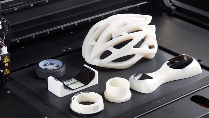 Many new users focus on printing only one part at a time until they are happy with the results, but as you get more experienced you also have the option of importing multiple STL files into the software and printing them simultaneously. This can save a lot of setup and post-processing time. For example, imagine printing all 32 pieces of a chess set overnight and then coming back to an entirely finished game set in the morning. It would take a lot more work to print each piece one at a time.
The Simplify3D Software gives you a wide array of options for multi-part printing so that you can choose the best method for your specific needs. There are 3 different multi-part printing modes that we will be talking about.
- Single Process Printing Mode
- Multiple Process, Continuous Printing Mode
- Multiple Process, Sequential Printing Mode
The number of processes refers to the number of FFF processes that you will be configuring to control the print settings for your parts. The Simplify3D Software has the unique ability of allowing you to use different settings for each model you print. For example, if the King and Queen pieces in your chess set require different settings, you can easily configure this in the software and still print these parts simultaneously. This is one of the big advantages of the software and we will cover this in more detail later on.
Single Process Printing Mode
The first technique we will be covering is the single process printing mode. This is the easiest of all three methods and one that most users are probably already familiar with. This is the technique you would want to use if all of your parts use the exact same slicing settings and you don’t need the reliability and performance benefits that sequential printing offers. For example, you might be printing four identical LEGO bricks, like in the model found here. The models are small, simple, and you can arrange them close to one another to prevent excessive oozing while moving between parts.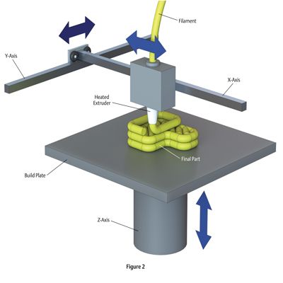 In this case, the single process printing mode is a great technique to use.
To begin, download and import the lego block STL file into the software. If you need to rename a model after importing, just double click on it to enter a new name. To make additional copies of this model, go to Models > Duplicate Selected Model. Make three identical copies and arrange them with a millimeter or two of spacing between them. Next, add a new FFF process and configure your slicing settings for the LEGO block models. In our case, we used medium quality, 60% infill. The last thing we need to do is select what models this specific FFF process will use. To do this, click the Select Models button in the bottom left of your FFF Settings. If we want to print all four pieces, make sure all four items are selected in the list or simply click the Select All button. Click Prepare to Print! to see the newly created printing instructions.
If you look at the G-Code preview, you should notice that the extruder prints all four pieces simultaneously. For each layer, the extruder prints one section of each block and then repeats this process. This results in a lot of movement back and forth between the different pieces, but as long as they are positioned fairly close together this should be okay.
Multiple Process, Continuous Printing Mode
For the next printing mode, we will be returning to the chess set example we described earlier. Go ahead and download the Knight and Pawn chess pieces. Import both of the STL files into the software and have a look at the features of the different models. You will notice that the pawn is very simplistic with gradual curves and features. The knight piece, on the other hand, has several fine detailed features such as eyes, hair, and teeth. It also has a fairly severe overhang on the chin of the model. In this case, it might be advantageous to use different slicing settings for these two models so that we can make sure they both print with the best quality possible.
As we learned in the previous section, we can use the Select Models button to determine what models a given FFF process uses. We could easily create one FFF process for the pawn and a second for the knight. That will give us more flexibility by letting us use the optimal settings for each model. First, let’s create the settings for the pawn. Create a new FFF process and call it “Pawn Process.” Use the Select Models button to make sure that this FFF process only applies to the pawn STL file. Now go ahead and configure the optimal settings for this model. We used 0.3mm layer heights with 3 outline perimeters and 0% infill. This will allow the part to print very quickly, which should be fine for the gradual rounded surfaces. If you want, you can Prepare and Preview this single process to make sure the pawn settings are configured properly.
Next, we will configure the settings for the knight. Add a new FFF process and call it the “Knight Process.” As before, use the Select Models button to make sure that this process only applies to the knight STL file. The settings for this part will be quite different than our pawn. We added support material for the chin overhang, used 0.15mm layer heights to help improve the quality of the fine features, and used 40% infill to help support the large flat surfaces at the top of the model. Save your settings and return to the main workspace.
The last thing we need to do is click the Prepare to Print! button to generate the printing instructions for our multiple FFF processes. The software will detect that you have multiple FFF processes and ask you which ones you want to merge together. Select both the “Pawn Process” and the “Knight Process.”
At the bottom of this window there is also an option to configure how these multiple processes will be combined. If we select the continuous printing mode, each process will be merged together, one layer after another. The result will look very similar to the single process printing mode that we described in the previous section, however, we now have optimized settings for each individual model.
Multiple Process, Sequential Printing Mode
The last printing mode we are going to talk about is sequential printing. This is a very useful printing mode that can help improve reliability and print quality, but you may need to re-arrange your models to use this technique. During sequential printing, the software will print multiple layers of a single model before transitioning to the next model. So it might print 30 layers of our pawn model before it moves over to the knight and prints 30 layers of it. This significantly reduces the amount of movement between models which results in a much cleaner surface finish. It also improves the reliability of the overall print since one model could actually separate from the build plate and fail without ruining the entire batch of parts. The image to the left illustrates the difference between the continuous (left) and sequential (right) printing modes. The thin red lines represent rapid movements where the nozzle is moving to a new location to begin printing. As you can see, the sequential printing mode results in much fewer movements between parts for faster and better looking prints.
So now that you know how sequential printing works, we need to check your hardware to determine how to re-arrange your parts. If the nozzle does not have sufficient clearance, your printer will end up colliding with one of the previously printed parts. The image to the left shows several common extruder configurations. Keep in mind that there may be external accessories such as fans or structural frames that reduce the available clearance of your extruder. The orange lines in the left image represent two parts being sequentially printed side-by-side. The spacing between these parts is an additional factor that determines if sequential printing would be successful. For example, the two bottom configurations do not have sufficient clearance with the current part spacing. However, if the spacing between the orange parts was doubled or tripled, the two bottom configurations would gain additional clearance.
To help illustrate this in more detail, let’s look at some real-world hardware. The Replicator 2 is a great example of how part spacing can affect your sequential printing clearance. The Replicator 2 blower fan sits right next to the extruder nozzle, which means that this printer has very little sequential printing clearance if the parts are arranged side-by-side and are only a few millimeters apart (see top image). However, if the part spacing is increased, the blower fan is no longer an issue and the X-axis rails become the new limiting factor (see bottom image). You could also arrange the parts so that one is positioned in front of the other, instead of side-by-side. As you can see, most printers will be able to use sequential printing, but it may require some extra planning and forethought to make sure the models are arranged in such a way to avoid any potential collisions.
Now that you have determined the best way to arrange your parts, the sequential printing setup process is very easy. You can follow the exact same steps outlined in the Multiple Process, Continuous Printing Section, however, we need to select a different option when we finally prepare our FFF processes. Instead of selecting the continuous printing mode when we choose what processes to prepare, we select the sequential printing option. This requires us to enter a value for the vertical clearance that was described above. For the Replicator 2 example, we have a measured clearance of 12mm, assuming the parts are far enough apart to avoid collisions with the blower fan. Enter the appropriate value for your printer and then press OK to create the combined G-Code file. If you followed these steps correctly, you can now enjoy better looking and more efficient multi-part prints!
We have now covered all of the multi-part printing modes available in the Simplify3D Software. Next time you have multiple parts to print, give these great time-saving techniques a try!
View the Complete Article Library
How to create models that are larger than the print volume of a 3D printer
Don't have a large format 3D printer yet? When evaluating the capabilities of a compact desktop 3D printer, do not limit yourself to print volume.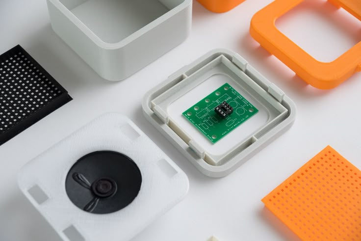 Many objects, like your smartphone or a bridge over a river, are made up of many individual components. Therefore, splitting the model into smaller parts that can be aligned after printing is a great solution for 3D printing large objects that do not fit on the platform.
Also, splitting the model can be a great way to get a high quality result, even if the whole model fits on the platform. This makes sense when multiple or opposing surfaces must be free from support structures, when the model has complex ledges, or contains cavities where liquid polymer can remain.
3D printing of various parts opens up new possibilities, for example, the creation of prefabricated structures from various materials or the combination of rigid and flexible parts to simulate the overmolding method.
When choosing a gluing method, it is necessary first of all to take into account the required degree of strength of the glued joints, which depends on the purpose of the models:
-
chemical: use adhesive on artwork, scale models, and complex shapes that are not intended for functional use and should not be impacted;
-
Mechanical: Provide threaded holes or sockets for attaching parts that require a secure mechanical connection, or repeatedly detaching and attaching components as needed.
This tutorial focuses on building large, prefabricated 3D stereolithographic (SLA) printed models with chemically bonded components. Read on to learn all the steps in this process, from model separation to post-processing for a professional finish.
Formlabs Form 3L is the first affordable, easy-to-use large format 3D printer optimized for reliable production of industrial-quality models. The Form 3L stereolithographic 3D printer features a huge print volume of 30 x 33.5 x 20 cm and unrivaled cost-effectiveness.
Meet the Form 3L
We recommend two ways to separate models: adding features to the design that will allow the parts to fit together, or separating the model with straight lines, which will require them to fit together properly during the bonding process.
Regardless of which method you choose, if you have a lot of parts, it's helpful to add a unique identifier (letters/numbers) for each one to make assembly easier.

Use CAD software to split a 3D model and add basic centering components such as slots, pins, slots, notches, and tabs, or more complex features such as dovetails and slots to match model folds.
Adding centering components to the design makes it easier to assemble parts.
Ideally, these components should make it easier to align and assemble parts, but can cause problems if they differ even slightly from your 3D models, preventing perfect centering. Therefore, it is best to use centering components only when the printer can print parts with accurate dimensions that are not subject to deformation.
Splitting a 3D model along straight lines requires less effort than adding components to center it. With this separation method, there are also fewer problems if the parts are slightly deformed or differ in size.
Adding IDs for each part makes the assembly process easier.
On the other hand, parts separated by straight lines can be time consuming to assemble, as each part must be manually centered and ensured that they all remain in the correct position until the adhesive is completely dry.
By default, when printing on a stereolithographic 3D printer, solid models without voids are obtained. Depending on the design, different requirements may apply to the manufacture of large items. In such cases, 3D printing the outer shell or converting the structure into a hollow is a great way to save a lot of material and time. When printing hollow models on a stereolithographic 3D printer, be sure to add ventilation holes to avoid creating cavities filled with air and pressurized resin.
SAMPLE PART
Experience Formlabs print quality first hand. We will send a free sample of the printed model directly to your office.
Request a free print sample
Converting a model design to a hollow saves a lot of time and material because the printer only needs to print the outer shell.
Learn more about how to save materials and time by hollowing out 3D models.
Depending on the size of the details and the purpose of the model, we recommend three mounting methods:
| Epoxy glue (5-30 min) | cyanoacrylate (CCA, Supercollah) | Resin | ||||
|---|---|---|---|---|---|---|
Square. | Large | Small/Medium | Small | |||
| Paintable | Yes | Yes | Yes | 9006 70072Medium | Low | Low |
For large parts and maximum adhesion, use 5-30 minute dry epoxy. It takes longer to dry than other adhesives, allowing you to fit large 3D printed parts but slows down the assembly process. Most 5-minute epoxy adhesives stop changing shape in as little as five minutes and cure by about 75% in less than an hour.
For large parts and maximum adhesion we recommend using epoxy adhesive.
The next option is cyanoacrylate (CA or superglue), which quickly forms a strong bond, ideal for small to medium sized parts. Thoroughly clean the part before applying CA to the surface, because contaminants adversely affect the quality of the connection. CA has a moderate impact strength, but is not recommended for models that require high strength.
For small models, you can simply use liquid resin from a stereolithographic 3D printer. Pour a small amount of resin into a tray from a bottle or cartridge, pick it up with a pipette or syringe, and place it on the surface to be bonded. Connect the parts and wipe off excess resin that may spill around the edges. Aim a 5mW (405µm wavelength) UV laser pointer at the contact area to cure the resin and bond the parts.
This method produces a chemical bond similar to 3D stereolithography printing, but is only suitable for bonding small surfaces as a low power light pointer cannot penetrate the model deep enough to create a strong bond.
Note. Protective equipment must be worn when working with polymers, including proper eye protection and gloves.
Download PDF
Don't have time to read the article now? Download it in PDF format.
Download as PDF
After assembling the model, it's time to move on to post-processing. This step includes geometric correction of the model to provide a smooth surface that matches the original 3D model, and aesthetic finishing to obtain a uniformly colored surface.
Depending on the precision of the printer and the size of the printed parts, there will almost always be slight voids or mismatches at the contact points. Automotive sealant (e.g. Bondo 907) adheres well to polymers, therefore, to eliminate such inconsistencies, it is recommended to apply it in a thin layer on the surface. Lightly sand the surface after each coat has dried to bring the model to its final shape.
Sealing models with automotive sealant (red area in image) will help eliminate small gaps and inconsistencies between parts.
Sanding helps remove traces of support structures and remaining inconsistencies in the model. Gently start sanding the surface with 150-grit sandpaper to remove traces of support structures and smooth edges where parts meet. Once the surface is smooth, sand it wet using 320 grit sandpaper to remove any remaining layer lines. Sand the surface in random motions so as not to leave marks. In most cases, these two methods will produce a fairly smooth surface, but you can continue to increase the grit of the sandpaper up to 2 times and, after wetting it, sand the entire model until the surface is reasonably smooth.
Power sanding is great for large flat surfaces, but can ruin fine details. Grinding of small models is recommended to be done by hand, and for large ones, a combination of manual and mechanical grinding is recommended.
Machining large parts with mechanical and manual grinding saves a lot of time. Power sanding is great for large, flat surfaces, but can ruin the fine details, sharp corners, and subtle contours that are typical of stereolithography. As a result of mechanical grinding, a lot of dust is also generated, so before starting processing, it is necessary to prepare the working area.
Note. The use of power tools requires full attention and the use of protective equipment.
The surface can be damaged very quickly without even realizing it, just by leaving the sander without moving.
When finished sanding the model, rinse it in soapy water to remove dust and debris and dry thoroughly before proceeding to the last step.
The primer helps the paint adhere to the surface and can indicate areas where additional sanding is needed or removal of traces of supports that you may have missed. The Universal Matte Gray Plastic Primer shows these spots exceptionally well. For best results, apply it to the surface in several thin coats. Sand critical areas and reapply a thin coat of primer. Repeat this process until the entire surface of the model is level.
Note. Use protective equipment during priming and painting, including a respirator to protect against paint fumes.
All-purpose matt gray primer for plastics is exceptionally good at showing fine details and helping to identify areas that need to be sanded down.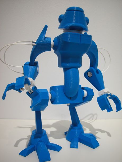
Find out more about sanding and priming in our detailed guide.
When painting with multiple colors, protect the model with a temporary coat. First, plan the order in which you will paint the model, depending on the color, transparency, and size of the area of a particular color. Start with small details so that fewer of them can be protected when painting with the main color. Apply painter's tape to the edges and corners. To quickly cover large areas, attach sheets of paper to them. Ribbon guides (laser cut) can also be useful for creating straight lines, circles and complex shapes.
When it comes to masking, figuring out the correct order is your first priority. In our case, the parts were first painted silver and the sections that would remain silver on the final part were then covered with painter's tape to hide them from the next l
painting. In our case, we first painted the parts silver and put masking tape on the areas that should remain silver in the finished model so that they do not get paint of a different color.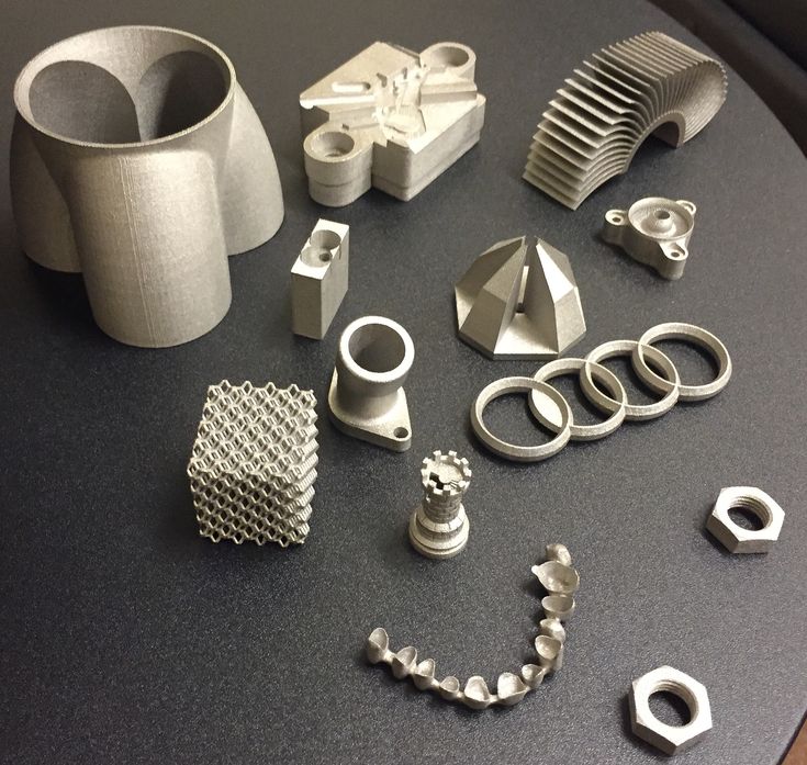
As with primer, several thin coats of paint should be applied for optimal results rather than one thick coat. Most spray paints will achieve the best color in warm and slightly damp conditions in the absence of wind. In this case, you must always follow the manufacturer's recommendations, which can be given on the paint container or in the technical documentation.
Consider the time the paint needs to dry: Allow layers to settle before applying the same color and allow the paint to dry completely before applying a new color.
The area where we applied masking tape is still silver.
Become an expert in painting 3D models with our detailed guide
Already wondering what your finished model will look like?
"Sorry sir, that R2-D2 over there is in excellent condition and inexpensive."
Formlabs optics designer Adrien Tanner created this R2-D2 model from 105 parts printed on a Formlabs stereolithographic 3D printer. It even has working electronics borrowed from the Form 2 printer - a galvanometer drive for sound reproduction, a cartridge dispenser for lamps, and a Z-axis drive for dome rotation.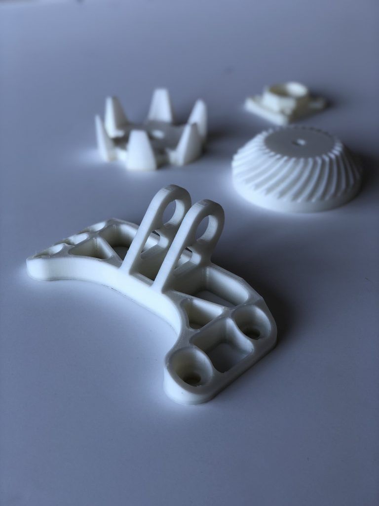 9The 0003
Form 3L is the first large-format 30 x 33.5 x 20 cm 3D printer for producing massive, industrial-quality models.
Reduce order processing time when outsourcing or manual work when assembling large-scale 3D models. Now you can print large 3D models in their entirety on the Form 3L, the first affordable large format SLA printer.
Want to see how stereolithographic parts work? Explore our resources to learn more about stereolithographic resins, or request a free sample to evaluate print quality for yourself.
Request a free print sample
(There is a solution) Will 3D printing multiple copies at the same time save time?
diy-3d-printer
I'm wondering - of course, if the 3D printer's table is big enough - printing multiple copies of the same print can save me a significant amount of time in a small production line, eliminating minor losses such as setup time , time after treatment, etc.
For example, if my print takes 10 hours, will printing 2x copies at the same time take 2x longer, increasing linearly, or will it be significantly less?
@Mehrad, 👍14
Talk
7 answers
Best answer:
▲ 11
Actually no.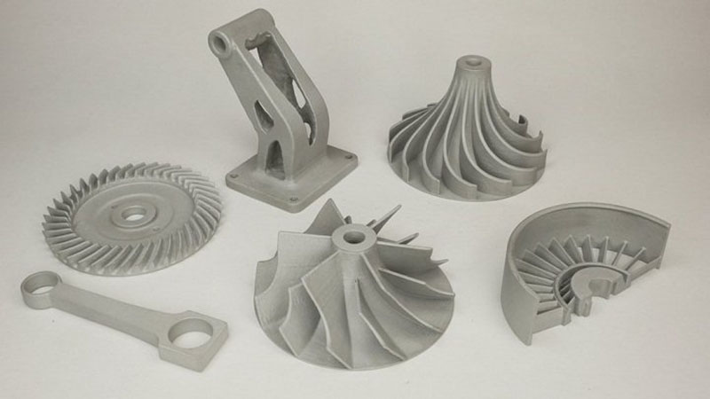 It will take a little longer for each addition. You also have a point of failure where you are knocked down and all prints are destroyed.
The fastest way to print multiple objects is to print one at a time. In fact, slic3r allows you to do just that with its sequential printing feature.
The reason is that the time it takes to go up 0.5mm, move a few mm to the next object, drops 0.5mm back.. Repeat for inner shells, outer shells, fills.. all add time. It doesn't seem like a lot until you've done it 14,000 times.
In the case of your example, this would be negligible. In more complex or well-spaced prints, it has a different story.
For extra extra speed, look into PLA loss casting...
, @ StarWind0
▲ 2
The percentage of production improvement generally depends on the size of the printed products. Unfortunately, it is volatile enough to make it difficult to give a precise answer.
Consider one single print. I am using my printer as an example. Other printers may have similar sequences. Printing has started and the table should be up to temperature. Once the set level is reached, the print head(s) must also reach temperature. Ignoring for the moment the duration of the print, it is then considered that the printer bed must cool down in order to release the print.
If you have ten items to print, you'll get nine times the time shown above. This can take up a significant amount of production time.
On the other hand, ten prints instead of one won't be of much use over time. You may lose some time in post-processing if you have stringing between elements.
Another complication is directly related to printing quantities. If you have one print failure, you've lost that time. For example, one print might take 18 minutes. Twelve minutes after printing, you have a clogged nozzle and have to stop working. This is an unfortunate loss.
With ten prints on the table, you print for two hours and fail. Much worse is the loss of time and productivity.
Obviously, it would be preferable to have a properly functioning printer and be able to work with confidence that these failures will not occur.
Hobby grade printers can't provide this level of confidence, but industrial/commercial grade printers should, further increasing the time it takes to print multiple items on a table.
If you have hot swappable plates, perhaps combined with the ability to preheat the incoming platen, you save time. I don't know enough about commercial grade printers to suggest such a feature exists. My printer table is attached with magnets and could be hot-swapped if I was careful. The table will begin to cool down quickly, making the preheated plate even more valuable. Instead, I'll just print a few articles and hope for the best.
, @ fred_dot_u
▲ 5
Yes and no. It depends.
For FDM printing, the print time in general scales linearly with the number of objects. However, some printers have a "minimum layer time" which prints smaller layers more slowly so that each layer takes at least this minimum time. This gives the seal enough time to cool.
Since the model shown in your example is quite small, it is likely that it will reach the minimum layer time. This means that printing one copy will take exactly the same time as printing two copies, which will take exactly the same time as printing three copies, until you reach the minimum layer time. At this point, adding more models will simply add some constant number of minutes to your print time.
If the model is large enough that the minimum layer time is not a factor, then printing objects one at a time is generally faster because you save on moves between layers of two objects (and also results in better printing, since moving between objects can leave stringing behind them).
This only applies to FDM printing. For DLP printing, the print time for a (set of) models only depends on their total height and therefore the number of layers required, since each layer takes the same amount of time regardless of the amount of material printed. So the times for 1, 2, 3,...n models are exactly the same.
There are many other types of printing in which the number of layers is much more important than the amount of material used, such as inkjet binder, SLA and SLS, in... there, as a rule, some time the cost of the material is printed, but The main factor in print time is the number of layers (and for SLS, the amount of time it takes for the volume to cool down after each print, which is quite significant.).
, @ Tom van der Zanden
▲ 8
Printing multiple parts can save you time .
The issues other posters point to are all great, but one factor that was neglected is the time it takes for you to clear the build plate and restart printing.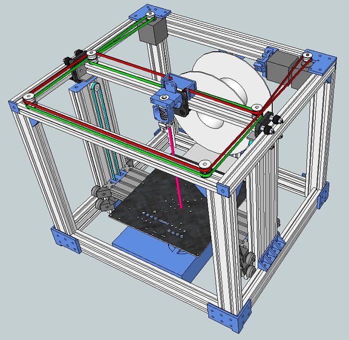 I found that for small parts (less than 1 inch cube) printing multiple parts at once was more convenient and minimally fast. Much of the time saved came from the fact that I could leave the printer for a few hours and work on other tasks without having to babysit the printer and wait for it to finish each part. I printed about 100-200 pieces this way. I ended up losing one "batch" when one part broke off and started causing problems, but I found it was a small price to pay for being able to do a lot of other things.
Everything will depend on the criticality of your deadline for completing the parts. If you're doing the giggle details and don't need them to be done immediately, then I'd say one at a time. Less risk of breakage, less wasted materials and time is not super critical. If you are producing parts for a prototype product that needs to be tested in the field for several weeks, I would choose small batches of a few parts. This will give you more time to work on other things, less exhaustion, and you can check in from time to time to see if everything is in order, usually by doing nothing, assuming everything is going well.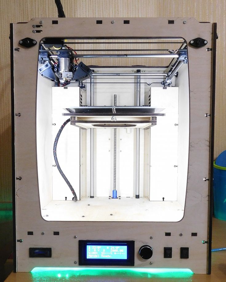
, @ Diesel
▲ 0
Actually the answer is yes and no. So I had to print 12 identical little objects for a science experiment. It's just that I made some stones from domes with some offset edges, anyway, the minimum wall width of my printers is 0.5mm. The volume of the objects was 2 cm3. The first print failed because they were detached, but then I connected 12 items with hardened 1x1x5mm cylinders in a blender and ran them through my cutter and they printed with no problems. After that I just cut off the cylinder and was ready to go. Just make sure your object is connected at every point facing each other. Based on your picture, it should be related something like this:
, @ Collin Elliott Clark
▲ 1
usually takes more than time to complete actual prints due to additional moves, but this saves you time in one important way: if you trust your printer, you can run a large batch and then just to leave .