How to join 3d printed parts
How To: Bond Your 3D Printed Parts
Learn how to properly bond your 3D printed parts and blend the seams in this in-depth guide.
Alec Richter
March 14, 2018
If you’ve ever split a 3D model larger than your build plate into smaller pieces so you can print it, you probably found yourself trying to reattach all the pieces. Sometimes, the pieces don’t butt against each other as cleanly as you’d like to, or there’s a huge gap between the seams that you can see through. If you have wanted to print a model larger than your print volume and you’ve never done it before, check out the article by our MatterHacker Pro, Scott, here.
There are several post-processing methods to help hide those seams or to reattach each piece with a cleaner seam, although some are more noxious than others.
There are two steps to this process: attaching and blending. Attaching each piece will be done with adhesives or solvents and blending will use various putties to actually fill it in.
Roughing the Edges of Your Prints Allows More Glue to Hit More Surface Area
Before you get into adhering your parts together, you’ll want to rough up the two surfaces you are going to stick together. This will give just a little more surface area for the adhesive to stick to, allowing for a stronger bond. With whatever grit sandpaper you have on hand (it really doesn’t matter as long as the surface feels rough when you’re done) sand the 3D print until it’s noticeably rougher than the clean sides.
For most materials (like PLA, ABS, or PETG), cyanoacrylate (or superglue) is going to be the most common and easiest way to keep two pieces together. Some more flexible materials, like TPE, TPU, or nylon, aren’t very reactive to superglue. While superglue’s biggest advantage is that it almost instantly cures, that’s also it’s biggest curse.
Super Glue is Extremely Easy and Widely Available, But it Can Be Somewhat Smelly
Any mistake you make with one edge not completely lining up with the next or any drips will solidify and stay there.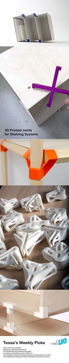 Sometimes it’s beneficial to have that immediacy in gluing your parts together, so you aren’t holding or clamping parts together in perpetuity. An unfortunate characteristic of super glue, however, is that it is harder than most putties or filaments, so any drips of superglue or seams that superglue spilled out from will be that much harder to hide. When you try sanding the seam, the surrounding area will start getting sanded before the seam, leaving you with a drip shaped island on your print.
An alternative to super glue is a 3D printing pen like Crafty Pen. You can utilize a Crafty Pen as a welding tool, using either the hot end to melt the two sides together, or using filament from it to fill in some of the larger holes. You can even use the Crafty Pen to bridge holes if your prints aren’t quite as flush as you planned them to be.
Using More of the Native Filament To Bond Your Print Can Help Fill Seams and Small Mistakes
JB Weld or 5 minute epoxy works well too. I personally find 5 minute epoxy is most helpful to back seams that are superglued together, to give it that extra bit of rigidity to keep the two parts together.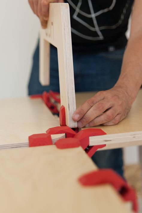 Of course, this is only viable if the back side isn’t visible or doesn’t need to look pretty. Either of these two are applied in basically the same way; mix up the two part of the epoxy and smear it onto each side of the parts that are going to be adhered, or spread on the JB weld onto both sides.
For a Serious Bond, JB Weld or Epoxy is Excellent - But Again, Can be a Bit Smelly - Use a Well Ventilated Area
Bondo Body Filler, filler primers, Evercoat Body Filler, Bondo Glazing and Spot Putty, wood filler, and 3M Acry-fill Spot Putty are all excellent choices to fill in the larger gaps or discrepancies between the two halves. Only consider using these putties and fillers on your 3D prints if you intend to finish and paint them, because not only will it be a significantly different color than your print, but it will also have a smoother finish than the layer line striations of a 3D print.
Using Bondo to Fill Seams and Mistakes is also Excellent - Multiple Applications with Liberal Sanding in Between Can Give You Incredible Results
Hopefully this gives you a good headstart on printing some really big projects on smaller desktop printers, because you don’t need to be limited by your build volume.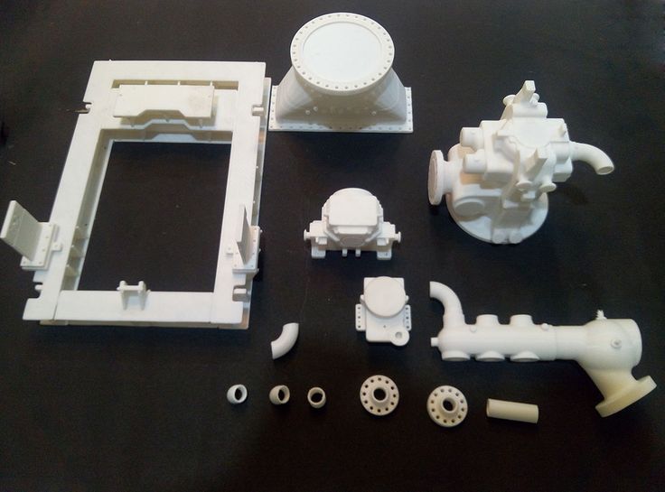 Of course, there are many different resources out there, so if you feel like I’ve missed any that you feel are important, feel free to leave a comment down below.
Happy printing!
Now, these are all adhesives, which means an adhesive force is what holds them together. Chemically, there are still two distinct parts with a sticky third material holding them together. 3D Gloop is different: it starts dissolving the plastic when it is applied, and when they are pressed together and time passes, the 3D Gloop evaporates and the plastic rehardens, leaving one part. There are a couple different formulations specific to 3D printing filaments, so make sure to use the PLA formula only on PLA. First thing's first: wear proper PPE like a respirator and goggles with adequate ventilation. To fuse parts simply apply 3D Gloop!, press and hold together for 15-30 seconds to achieve a strong tack hold. Bonds will achieve 80% strength after an hour and full strength within 6 hours of application.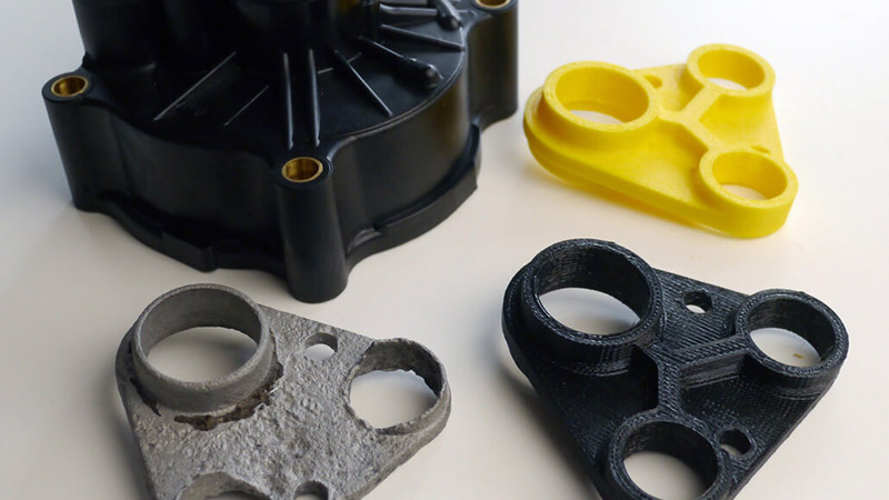
How To Attach 3D Printed Parts
Affiliate Disclaimer: Some of the product links on this page are affiliate links. We may recieve commission if you purchase something after using one of these links, but using these links will never affect the price you pay.Attaching 3D printed parts together is something you’ll probably run into sooner rather than later if you’re 3D printing often.
A lot of the time its because elements are just too large to fit on a print bed, meaning you need to print a full model in segments. Other times, you may be printing an object which simply cannot be printed as a single 3D model.
However you’ve come across the issue of how to attach 3D printed parts, you’ll need to find a solution. And that solution can come in many forms, as there are a few tried and tested techniques when it comes to attaching 3D prints.
The best options for attaching 3D printed parts
Technique 1 – Gluing 3D printed parts together
Technique 2 – What is a 3D printed snap-fit?
Gluing your 3D printed parts
Gluing step 1 – Prepping your 3D model
Gluing step 2 – Choosing a glue
Printing 3D joints and snap-fits
Can you use any material for 3D printed joints?
The two main types of snap-fit
Conclusion
The best options for attaching 3D printed parts
There are two primary approaches when it comes to attaching 3D printed parts together, gluing and snap-fit. Let’s take a quick look at the two options, and then I’ll look at both methods in more detail.
Technique 1 – Gluing 3D printed parts together
Gluing 3D printed parts together is possibly the most common form of 3D model assembly. When done correctly, a glued 3D model can look very professional with very little evidence of the glue or seam.
Gluing involves a process similar to smoothing your 3D model, where you’ll spend the majority of your time preparing your model. Once you’ve spent some time prepping, you can then form a really strong, and almost seamless bond with the glue of your choice.
There are a variety of different methods to gluing your model together, which I’ll cover in more detail below.
Technique 2 – What is a 3D printed snap-fit?
If you are assembling a complex or move-able 3D object, then gluing just isn’t right. Instead you should look at printing a joint into your model. A joint will allow the model to join together without any outside influence such as gluing.
One of the most common form of 3D printed joints are snap-fits. These joints kind of do what they say on the tin. They snap together thanks to part of the joint being flexible. And once attached, they’re very sturdy and stable.
Essentially, one part of your 3D model will have a hook or rod built in. While the other part will have a hole or slot where the hook fits in to. You then snap them together to complete your object. The flexibility of the hook allows it to bend in to the join, while “snapping” in to place to lock the model together.
Let’s look at both methods in more detail, starting with the gluing technique.
Gluing your 3D printed parts
Gluing is one of the most accessible methods of 3D print assembly. And it can be one of the most effective. When done correctly, a glued 3D model can be sturdy for years, and it can be very hard to see the seam. But how do you achieve this level of finish?
Gluing step 1 – Prepping your 3D model
Gluing a 3D model is essentially the method of joining two parts together along a seam.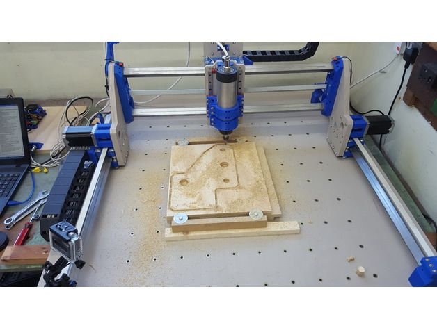 Therefor that seam needs to be prepared correctly to allow the bond to be as strong as it possibly can.
As I mentioned in my overview above, prepping your model is very similar to smoothing. If you want to learn how to smooth your 3D model, read my complete guide to smoothing here.
The main difference for prepping a model for gluing rather than smoothing completely, is that you will want to stop part way through the full smoothing process.
Essentially you will want to use sand paper to rough up the areas which are going to be joined together, just like we do when smoothing. However, you will only want to sand the join with a fairly large grit sandpaper.
The idea is to create a visibly roughened area. This will allow the glue to bond to the surface better, in turn forming a much stronger bond.
Once you have sanded your edges, make sure you clean away any excess dust. You will want to make sure the edges are as clean as possible before applying the glue.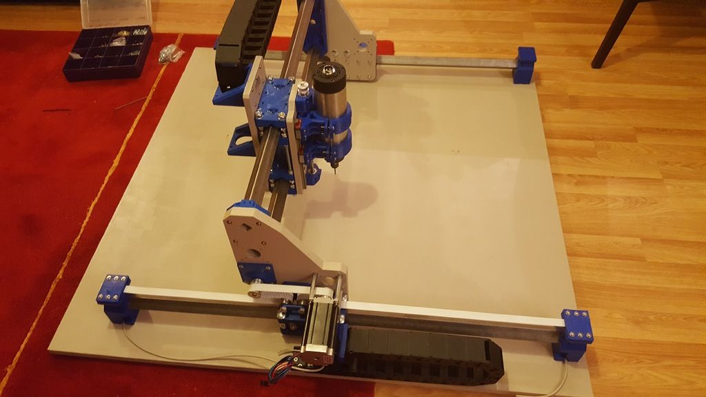
Gluing step 2 – Choosing a glue
There are a few different types of glue that you can choose from when it comes to gluing a 3D model together. One of the most accessible is superglue, and most 3D print materials such as PLA and ABS both adhere well to superglue.
If you are using a print material which has more flex to it such as TPE, you may want to look at a different adhesive.
Superglue
Superglue is a great choice of adhesive for assembling 3D printed parts for many reasons. It’s easy to use, cures quickly, drys clear and most people have it in the house already. If you don’t, it can be very cheap to pick up.
For those reasons it is one of the most popular adhesives within the community. As I mentioned, many materials lend bond well with superglue, ABS, PLA and PETG to name a few.
When using superglue, you should absolutely stick to my prep technique above. Use a medium-large grit sandpaper to rough up your edges. You can always use a finer grit if you find the edges appear too rough. Remember, you just want enough roughness to allow the glue to grip.
Once you’ve finished sanding, ensure you fully clean the surfaces and clean away any dust or dirt. You can do this with a rubbing alcohol such as isopropyl. Make sure you let the areas dry fully before applying any glue.
Top tip: Use disposable gloves when applying superglue as it is extremely fast curing. If you get any on your hands you could easily become a little unstuck (pun intended!).
Solvent
Rather than using glue to attach your 3D printed parts, you can actually fuse them together by slightly melting them. This may sound counter-intuitive, however if you use just the right amount of solvent, you can create a strong and invisible seam.
The best part about using solvent as a bonding method, is that once your 3D print is bonded together there is absolutely no glue left behind. All you have is your 3D printed parts, and a very tidy seam.
Solvent, such as Acetone, works by ever so slightly melting the edges of your parts.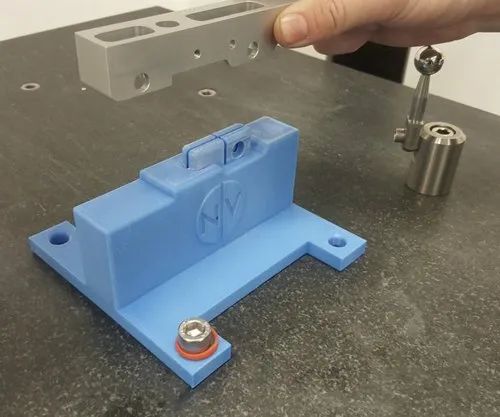 Then while in a melted state, you hold your parts together, clamping them for a few hours or over night. Once the plastic has hardened, the two parts will have bonded together.
Solvent is a great technique to use on ABS, and some PLA materials as well. It could be well worth experimenting with this method if you are becoming tired of sanding away excess glue.
Top tip: Apply using a natural brush for more control over your placement. If your parts don’t sit flush together, you can mix some excess filament to your acetone to create a thicker texture. This will allow you to essentially mold your solvent solution to fill any gaps.
Heat
Using a similar technique to solvent above, you can use heat on its own to create a bond. This method involves absolute precision as you will be using a heat gun or soldering iron to slightly melt part of your 3D printed part.
It can be tricky with heat, to direct it to the area you intend, so I would recommend trying both methods above before moving onto heat.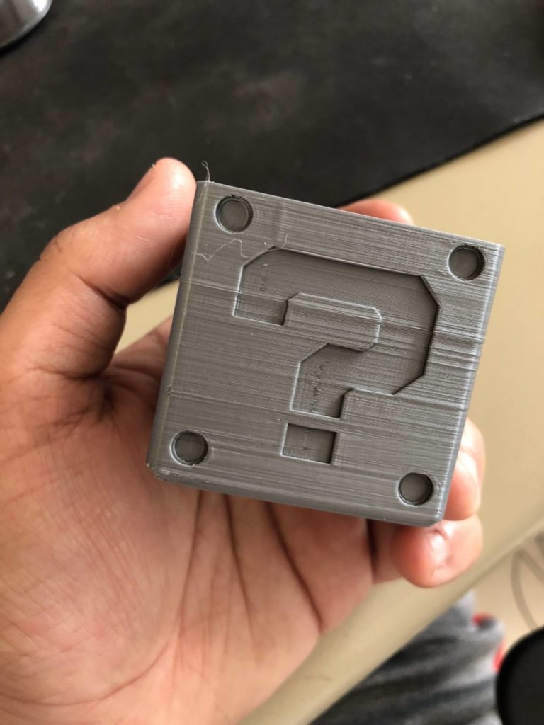
However, if you fancy giving this a go, it can be very effective. Similar to acetone, you wont get any residue or third party substance left on your parts after bonding. so you can create a seamless bond if done correctly.
The method involves directing heat using a soldering iron, or a hot air gun to the edges of your parts. And then as the parts start to harden, hold them together with a clamp, and they will form a good bond.
Top tip: Speed is crucial with this method, as you will need to heat all edges that will form a bond evenly. This can be hard because as soon as you remove the heat source the part will start to harden.
3D Printing Pen
Another technique of forming a bond is using a 3D printed pen. This is a good technique to add to the list if you don’t want a visible bond to show. By using the same colour and material as your 3D printed parts, you can create a completely seamless bond.
Essentially, this method involves you drawing along your edge line in the same material used to print your parts.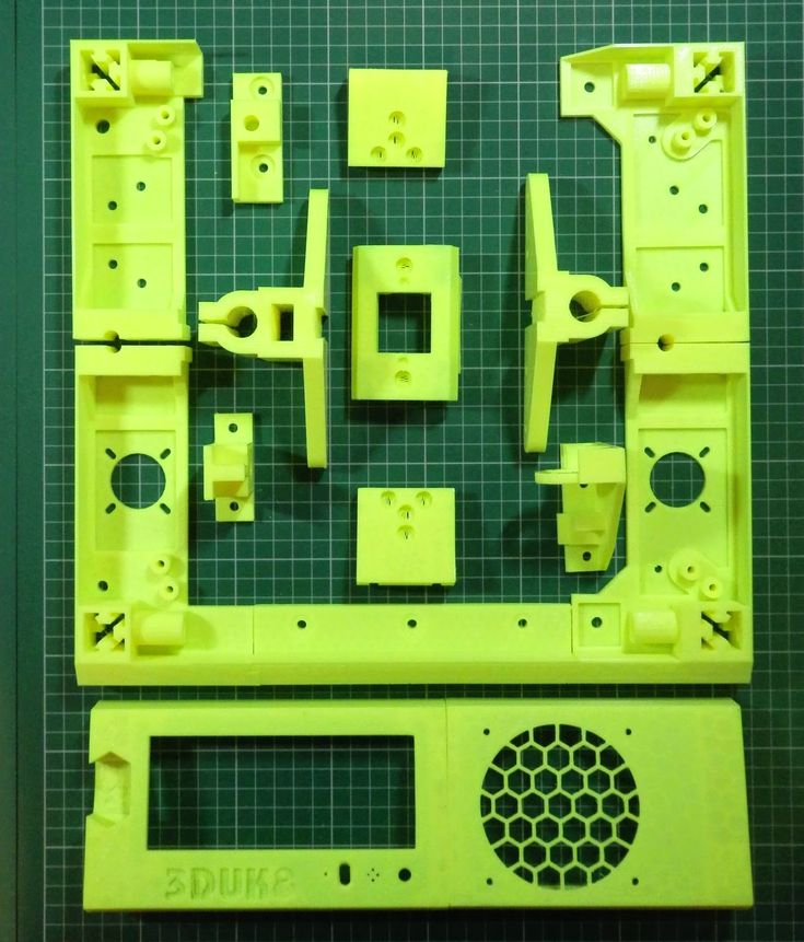 And then fixing your 3D printed parts together for a few hours while the new filament hardens.
You can achieve some very good results using this method, however the bond generally isn’t as strong as using glue or solvent.
Top tip: Only use this technique on decorative or non functional models, as the bond can break away over time. Match the material colour to create an almost seamless bond. And ensure you clean your edges thoroughly before applying for maximum strength!
Epoxy
Using epoxy to bond together parts is another efficient method, and is very similar to using any form of glue. Epoxy is extremely strong once cured, meaning your bond should hold up very well.
It can also be used as a filler, similar to the method I mentioned above with solvent. So if your edges aren’t a perfect match, epoxy can sit in any gaps that appear.
The main downside of using epoxy is that it requires much more preparation than using other forms of glue.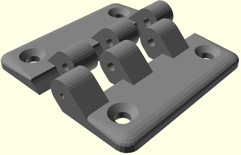 Generally epoxy comes in two tubes, which then need to be combined to form the final epoxy.
One of the benefits is that you can get some extremely quick curing epoxy, minimising your clamping time.
Top tip: If you melt down and mix in some filament, into your epoxy, you can create a filler material allowing you to fill any uneven surfaces.
Printing 3D joints and snap-fits
Designing your models with an in-built joint is one of my favourite ways to create larger, more complex 3D prints. It allows for moving mechanisms, and it looks extremely mechanical and interesting.
If you design the joints in the correct way, they can provide both flexibility and strength to your model.
It is also a fantastic way to save time assembling your model. Just think, gone are all of those hours of preparing your edges, gluing, clamping, curing and finishing your edge. All of that assembly can take up to 24 hours! And most of that time vanishes when using snap-fit joints.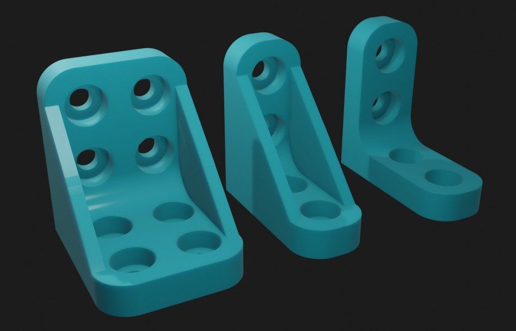
If you are printing multiples of the same object, either for manufacturing or retail purposes. That time can quickly add up!
Can you use any material for 3D printed joints?
You can use almost any method of 3D printing to create snap-fit joints. This includes all popular methods such as FDM, SLA and SLS. However your mileage, strength and accuracy may differ depending on your method.
FDM printed joints
As we know, FDM printing is less accurate than both SLA and SLS, but is much more accessible. You can still print snap-fit joints with FDM, however using regular PLA might not be the best material choice.
You should look to opt for a more stress resistant material like ABS, as this will hold up much better under the strain of movement.
SLA printed joints
An SLA 3D printer will produce a much more accurate fit when it comes to printing joints. However, the resin itself isn’t designed to be repeatedly moved, meaning it isn’t the strongest. You can get specific durable SLA resin which will fair much better than regular resin.
SLS printed joints
SLS printing is similar in many ways to SLA. They both use a laser to essentially build your 3D print. However the material is much different. An SLA 3D printer uses liquid resign, which hardens under the laser. And a SLS 3D printer uses powder which is fused together.
The latter is more costly to produce, but is great to prototype strong 3D printed joints. SLS 3D printing is my preferred method of printing snap-fit joints which are designed to last.
Top tip: You can always use the other methods to quickly prototype your joints, before committing to the costlier SLS method. SLS nylon is a fantastic choice for printing joints.
The two main types of snap-fit
There are multiple types of snap-fit joints, however there are two which are much more common place than others. They are cantilever and annular snap-fits.
Cantilever snap-fits
Cantilever is by far the most common form of snap-fit joint, and works in a very similar fashion that I mentioned at the top of this guide.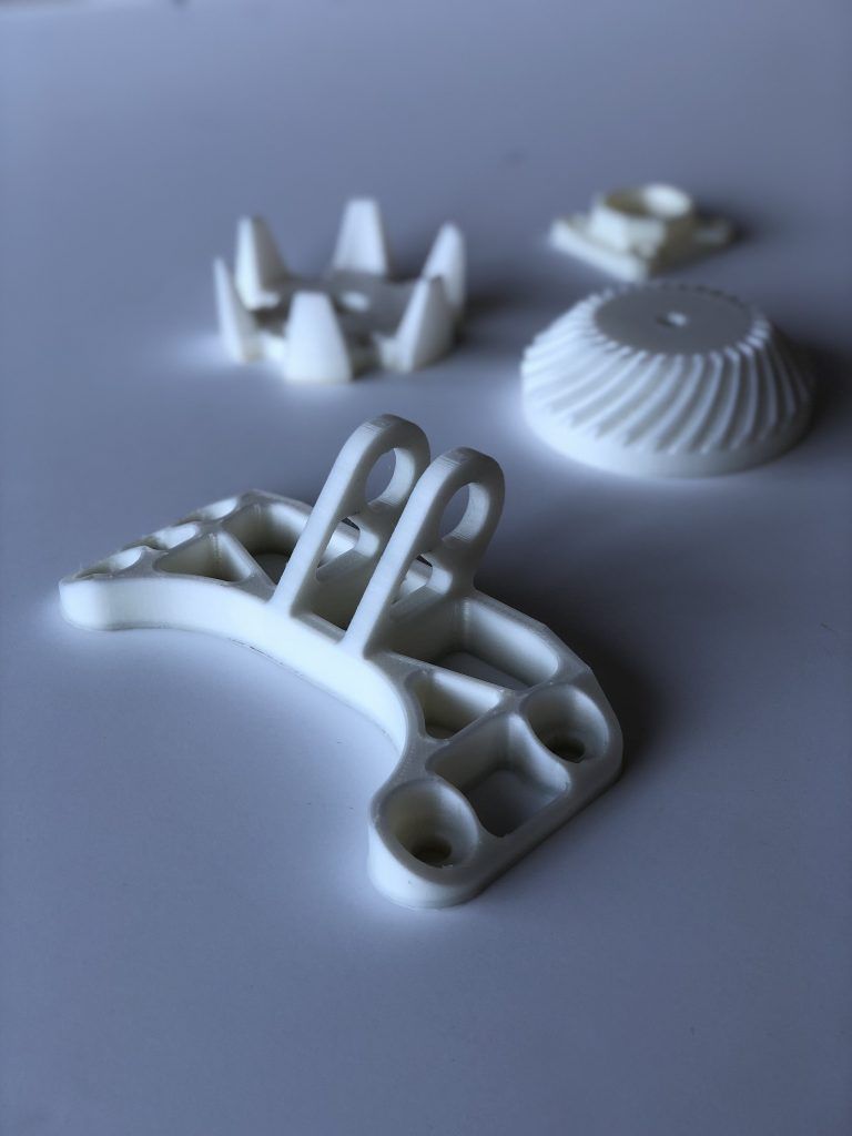 One part will have a hook, and the other part will have a slot for that hook to snap into.
You connect the two by pushing the hook into the slot or cut-out and it will “snap” in to place. The two elements will lock together forming a strong join.
Annular snap-fits
When thinking about annular snap-fits, think about a pen cap, or a push-pull bottle cap. With annular joints, you can push one part of your model over the other forming a seal. This seal can be waterproof.
The method can only be applied to circular parts, and uses grooves on both parts. You build in a groove into your main 3D printed part, and then the exact same groove but inverted into your secondary part.
As you push the parts together, the grooves will interlock forming your seal. Annular joints are much more specialist and have much fewer applications.
How to design and implement snap-fits
Now we’ve run through exactly how snap-fits work, lets look at a few top tips on how to design strong and sturdy snap-fits.
The most important things to remember when designing snap-fits is to ensure you create a strong joint. One which will last multiple uses and wont bend or snap under stress.
To achieve this, you need to design your joint correctly. Ensure that your joint fits flush with your slot once attached, and that the joint isn’t in a constant state of stress. Meaning your snap-fit should return to its original position once attached, and shouldn’t remain bent or distorted while in position.
You can also look to widen your joint itself to distribute the stress better. Widening your joint isn’t always possible, but I’d recommend doing so if your design allows for it.
Also look to fillet your corners. Filleting any corner, especially at the base of your cantilever, distributes stress much better than a harsh 90 degree corner.
Look to implement an easy method of removal if your planning on using your joint often. You can implement holes allowing you to push your hook away from the build when disassembling.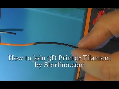
Finally, try to build your cantilever in the correct direction. Building it vertically will inherently weaken your part due to the way that anisotropic method that 3D prints construct objects. Try to print your cantilever horizontally where possible.
Conclusion
Designing 3D printed parts to be joined shouldn’t ever be a tricky task. There are a multitude of ways to bond together multiple parts effectively, both to form a solid object, and a move-able joint.
Hopefully the guide above will help alleviate any potential stress that you may have with assembly. And provide you with a few techniques to experiment with. Happy 3D printing!
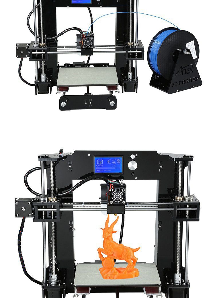
Important for beginners. Inside of a 3D printed part
The information that we will cover in the article is intended primarily for users who are just getting acquainted with 3D printing. Beginners have to learn a lot of nuances and questions in order to become experts. We hope this article will help answer some of your questions.
Structure of a 3D printed part
So that you like the result of printing and the part performs its functions (technical or aesthetic - no difference), think about its structure in advance.
As, for example, the construction of a house is made of bricks or logs, so any part printed on a 3D printer consists of layers that are superimposed on each other from the bottom up. Layers can be of different heights and printed with different nozzles - the smaller the nozzle diameter, the lower the layer height needs to be set and vice versa. For example, the vase in the figure below is printed with a nozzle with a diameter of 1 mm, a layer height of 800 microns.
When printing the vase, the characteristics are set so that the layers are clearly visible and tangible
How does layer height affect the finished model? The layered part will have more roughness and at times lower print accuracy (the thicker the nozzle, the larger the corner print radius).
also includes the perimeter and internal filling:
Perimeters create the form of the object
Filling can be made in the form of a pattern 9000
Interior filling can be performed in the form and may be complete. Forms of its execution: honeycombs, rectangles, lines, Gilbert curve, etc. The fill pattern affects the rigidity of the part, as well as the duration of printing and material consumption.
The number of outer and inner perimeters affects the strength of the part. If we set more perimeters, then the part will be stronger.
Almost always the optimal number of perimeters is 2-3.
with yellow, the perimeters (internal and external) are indicated by
there are more perimeters (5 pieces) and the part became stronger than
The larger perimeters is also established so that it is also established so that it appears to appear in order the ability to make a hole in the model without damaging it, and also for threading.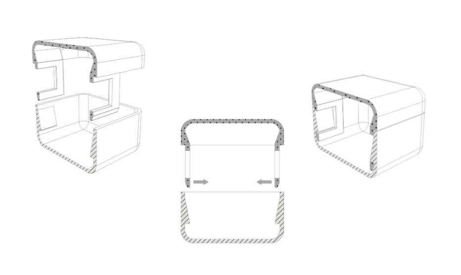
There are bottom and top layers. They are easy to distinguish: the bottom layer will be smooth and glossy, as it adhered tightly to the glass during printing, and the top layer will be rough due to micro-marks of the nozzle.
The lower layer is smooth due to contact with a glass table
A slightly rough
To get a more smooth surface, it is necessary layer. In this case, the nozzle makes more passes (eg nozzle d=0.5 mm, extrusion width on the upper layers = 0.25 mm). Instead of one line of top fill, the extruder will make two lines and the surface texture will become denser and smoother.
Extrusion Width is a configurable parameter that sets the width of the line when printing (the thickness of the plastic at the exit) smoothes unevenness with a nozzle.An infill is a structure within a part (perimeters). The part is most often not 100% filled and is not a monolith, but this does not affect the loss of strength, since the filling can be made in the form of a pattern that holds the part together and gives it rigidity.
How to take into account 3D printing when modeling a part
Often, people who first encountered 3D printing use their previously acquired design and modeling skills, or knowledge of resistance materials to model printed parts. In fact, in addition to knowledge of modeling, you need to take into account the features of 3D printing itself. More on these details below:
Part anisotropy - the strength of a part in only one direction.
Imagine that our task is to print a bracket that will be attached to the wall with 2 holes (see the figure below).
Spoiler: you can't model the bracket in this way
With this simulation, it turns out that the part will carry the load along the layers. Most likely the bracket will not withstand the load and break. When using technical plastics, the risk of breakage of the part is reduced (their sintering of the layers is better), but, nevertheless, you need to design the model correctly - place it across (put it on the table).
We recommend positioning the model in this way. In addition, support can be dispensed with e k
When printing the bracket in the supine position, the layers are perpendicular to the load vector. Such a detail will be stronger. It can be compared with the fibers of a tree - if the load is directed across the fibers, then it will be easier to break it. When we place the model horizontally, the layers are arranged correctly, so the product should be more practical and stronger.
First layer flat
Parts are being printed on a flat table and you need to plan in advance the flat part from which to start printing
For example, let's look at this detail:
Dmitry looks at the detail and understands that it will not be possible to print the same one without supports. The grooves are located just above the plane of the part and
As a result, the part was printed in this position
There was a lot of support at the bottom and a lot of material wasted.
But such a detail could not be printed otherwise.
By the way, this part was not designed for 3D printing. If its printing was originally supposed, then the issue of protruding grooves would probably be solved by drowning them behind the plane. This could have allowed the printing of the part with the maximum area of contact with the table.
If the contact area is small, then there will be a high probability that that the part will peel off the table when printing.
Consider the example of a rocket:
Imagine that its three small nozzles are slightly shorter than the main average e
In this case, there will be only a couple of perimeters with which it is in contact with the table (central nozzle) . This makes it very unstable when printing, and the movement of the extruder can drop nozzles hanging around the perimeter. Therefore, when modeling a rocket, all elements of the base were made on the same level.

Overhanging elements
Another point related to the specifics of preparing the model for printing.
Let's start with the fact that models with overhanging elements should be avoided :)
If such an element appears in the part, then most likely it will go to print with supports (and eventually they will have to be removed), or the element will sag. How to solve a problem? If possible, avoid models with overhanging elements, you can add a chamfer (cut corner).
There will be no sag at 45°. For example, the wings of the already mentioned rocket are printed without supports
Thin walls in the model
Often in modeling it is necessary to make a wall of a certain thickness. How to model a thin wall so that there are no errors during slicing:
Heat gun wall thickness = 1 mm, with a slight 1.5 mm thickening at the edges
Dmitry indicates the wall thickness of the hair dryer
The wall must be modeled with a thickness that is a multiple of the nozzle diameter (nozzle = 0.
5 mm, which means the wall is 1 mm or 1.5 mm). But what if there is no multiple match, and we need to make a layer 0.4 mm thick?
The answer is simple: you need to increase the width of the extrusion
A good example of increasing the width of the extrusion and
How can I save printing time? A few tips.
Let's imagine that we need to print a non-functional part (cover, casing) in order to “try it on” or “attach” it somewhere. In a word, make sure it fits its destination. Such a blank can be printed without internal filling at all (only with two or three perimeters), if there are no overhanging elements. The part will be empty and light, but it will do very well for trying on.
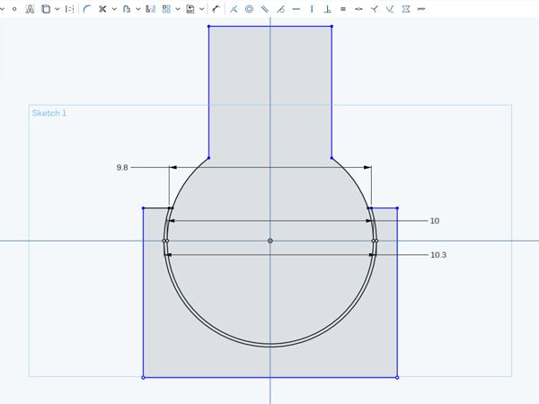
Consider the example of printing the FIFA Cup. This goblet can be printed without infill, but we have it with a small, thin infill bar from the base to the top of the sphere (an option in the infill slicer only needed).
Due to this, it does not sag. The case is printed entirely with perimeters.
In general, you can use the modifier and start filling only at the top. Until this part, printing is done only by perimeters and the pole of the sphere does not sag. It is also possible to set a very small extrusion width for filling, in which case the “inner wool” will not allow the top to fall through.
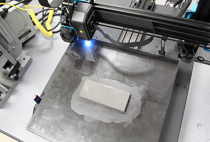
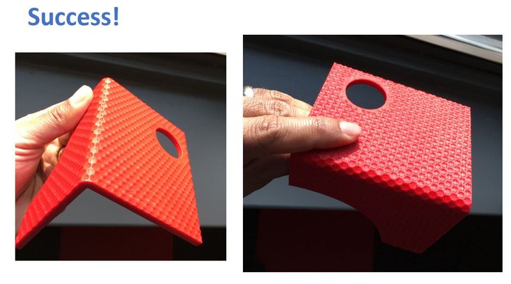
If we need a part whose surface does not have to be very smooth, then we can take a nozzle with a larger diameter (0.8 mm, 1 mm) and set a higher layer height.
The bottom square piece (see photo below) is printed with a 0.8 mm nozzle and a fairly high layer of 0.5 mm. It took 15 minutes to print. The top part is printed with a 0.5 mm nozzle and a 0.15 mm layer. This part is very smooth, but it took 39 minutes to print.
15 and 39minutes. Agree, there is a noticeable difference?
The time savings when printing the first part is very noticeable, and when printing a large part, you can save hours without losing accuracy, but only a little in appearance.
Layer height is the main parameter that significantly affects the speed of printing.
You can also save time by printing through-the-layer infill and increasing the extrusion ratio per infill (there will be only one infill layer per two perimeter layers).
Dual extrusion
Let's imagine that we urgently need an externally smooth and aesthetic part. A dual extruder printer will help with this. We will print the perimeters with one nozzle diameter, and the filling with another.
The perimeter can be printed with a 0.5 mm nozzle. The wall and layer will be thin (0.2mm layer)
The infill is printed by another extruder with a 1mm nozzle and through the layer.
Important: this can only be done on a printer whose two extruders are located at different heights.
As a result, we get an externally beautiful part, which is also rigid and strong due to the filling of 1 mm.
If the part was printed completely with this nozzle, then small seams on the perimeter or bumps at the corners become noticeable.
Thank you for reading! Leave comments, share your observations and tips for 3D beginners, ask questions :)
Link to webinar on 3D Printed Part Interior: COME IN AND LOOK AT
Threaded Connection of 3D Printed Parts
When creating complex or large models, parts often need to be printed separately and then connected. One of the most effective connections is threaded.
When connecting parts, it becomes possible to create objects that are larger than the working area of the printer. You can also end up with items of different colors and from different materials. Epoxy and other types of adhesives work quite well in some cases, but they are not compatible with all materials. In addition, these substances hold together tightly, so nothing can be changed later. If you connect the parts with screws, then the fastening is sometimes more durable than with glue or epoxy, and the structure can then be disassembled and adjusted.
In this article, we will look at the simplest and most effective threading techniques.
Read also:
How to print gears on a 3D printer
How to make a part more durable
5 safe ways to remove a printout
What filling out (Infill)
How to get in details
Gnegmar
One of the most effective ways to use a threaded connection is to create a socket or pocket where the nut will fit. Leave at least 2mm between the top of your part and the nut socket. This will allow you to apply enough force without breaking the part.
To design the socket, draw the nut you are using in the CAD program. Keep in mind that you will need to leave 0.3-0.5 mm tolerance, for the nut to go in without interference. Half of the drawing will remain the same, while the other half will be cut and extended to the outer wall of your part.
You won't like using props in the nut sockets because getting the props out is not an easy job.
To make it work, , seal the hole directly above the socket to a depth equal to the printing layer of (with a layer of 0.2 mm, 0.2 mm of plastic should be extruded). This will better cover the void, and then the screw will easily penetrate the hole through one layer.
Self Tapping Screws
This is one of the easiest joining techniques as it involves minimal design changes. We are talking about extruding the desired thread into the part, with the help of which the fastening will then be carried out.
To do this, measure the minimum and maximum diameters of the existing self-tapping screw. It is easiest to measure the minimum diameter at the end of the screw, and the maximum diameter at any of the threads. The screw will cut through the desired “tunnel”. Remember to use a self-tapping screw that matches your material. Self-tapping screws for metal and plastic are different screws.
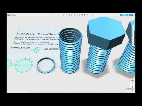
Thread Printing
This is perhaps the most ambitious technique, as it requires you to measure the size of the screw being used and draw a thread underneath it.
Most threaded profiles are very intricate and have steep overhanging angles - up to 80 degrees. FDM printers, when printing such parts, enter into an unequal battle with them, so this is more of an option for SLA. To get a more detailed understanding of thread printing on SLA printers, you can read the post on Formlabs. Most of the tricks discussed there apply to FDM technology as well.
The process of thread design will differ depending on the program in which it is carried out. In general, you will need to create a drawing for the overlapping parts of the screw, and then make a spiral along which these parts will be cut.
Heat Fit
This technique is only available for FDM because most compatible materials melt at relatively low temperatures. Make a notch for your nut, just make it about 0.5 mm smaller than the nut itself. Position the nut over the notch and remove the soldering iron. Heat the nut with a soldering iron until it sinks into the part.
Learn more