3D printer problem solving
Blobs and Zits | Simplify3D Software
Blobs and Zits
During your 3D print, the extruder must constantly stop and start extruding as it moves to different portions of the build platform. Most extruders are very good at producing a uniform extrusion while they are running, however, each time the extruder is turned off and on again, it can create extra variation. For example, if you look at the outer shell of your 3D print, you may notice a small mark on the surface that represents the location where the extruder started printing that section of plastic. The extruder had to start printing the outer shell of your 3D model at that specific location, and then it eventually returned to that location when the entire shell had been printed. These marks are commonly referred to as blobs or zits. As you can imagine, it is difficult to join two pieces of plastic together without leaving any mark whatsoever, but there are several tools in Simplify3D that can be used to minimize the appearance of these surface blemishes.
Common Solutions
Retraction and coasting settings
If you start to notice small defects on the surface of your print, the best way to diagnose what is causing them is to watch closely as each perimeter of your part is printed. Does the defect appear the moment the extruder starts printing the perimeter? Or does it only appear later when the perimeter is completed and the extruder is coming to a stop? If the defect appears right away at the beginning of the loop, then it’s possible your retraction settings need to be adjusted slightly. Click on “Edit Process Settings” and go to the Extruders tab. Right below the retraction distance, there is a setting labeled “Extra Restart Distance.” This option determines the difference between the retraction distance when the extruder is stopping and the priming distance that is used when the extruder is restarting. If you notice a surface defect right at the beginning of the perimeter, then your extruder is likely priming too much plastic. You can reduce the priming distance by entering a negative value for the extra restart distance. For example, if your retraction distance is 1.0mm, and the extra restart distance is -0.2mm (note the negative sign), then each time your extruder stops, it will retract 1.0mm of plastic. However, each time the extruder has to start extruding again, it will only push 0.8mm of plastic back into the nozzle. Adjust this setting until the defect no longer appears when the extruder initially begins printing the perimeter.
If the defect does not occur until the end of the perimeter when the extruder is coming to a stop, then there is a different setting to adjust. This setting is called coasting. You can find it right below the retraction settings on the Extruder tab. Coasting will turn off your extruder a short distance before the end of the perimeter to relieve the pressure that is built up within the nozzle. Enable this option and increase the value until you no longer notice a defect appearing at the end of each perimeter when the extruder is coming to a stop. Typically, a coasting distance between 0.2-0.5mm is enough to have a noticeable impact.
Avoid unnecessary retractions
The retraction and coasting settings mentioned above can help avoid defects each time the nozzle retracts, however, in some cases, it is better to simply avoid the retractions all together. This way the extruder never has to reverse direction and can continue a nice uniform extrusion. This is particularly important for machines that use a Bowden extruder, as the long distance between the extruder motor and the nozzle makes retractions more troublesome. To adjust the settings that control when a retraction takes place, go to the Advanced tab and look for the “Ooze Control Behavior” section. This section contains many useful settings that can modify the behavior of your 3D printer. As was mentioned in the Stringing or Oozing section, retractions are primarily used to prevent the nozzle from oozing as it moves between different parts of your print. However, if the nozzle is not going to cross an open space, the oozing that occurs will be on the inside of the model and won’t be visible from the outside. For this reason, many printers will have the “Only retract when crossing open spaces” option enabled to avoid unnecessary retractions.
Another related setting can be found in the “Movement Behavior” section. If your printer is only going to retract when crossing open spaces, then it would be beneficial to avoid these open spaces as much as possible. Simplify3D includes an extremely useful feature that can divert the travel path of the extruder to avoid crossing an outline perimeter. If the extruder can avoid crossing the outline by changing the travel path, then a retraction won’t be needed. To use this feature, simply enable the “Avoid crossing outline for travel movement” option.
Non-stationary retractions
Another extremely useful feature in Simplify3D is the ability to perform non-stationary retractions. This is particularly useful for bowden extruders that build up a lot of pressure inside the nozzle while printing. Typically when these types of machines stop extruding, the excess pressure is still likely to create a blob if the extruder is standing still. So Simplify3D has added a unique option that allows you to keep the nozzle moving while it performs its retraction. This means you are less likely to see a stationary blob since the extruder is constant moving during this process. To enable this option, we have to adjust a few settings. First, click “Edit Process Settings” and go to the Extruder tab. Make sure that the “Wipe Nozzle” option is enabled. This will tell the printer to wipe the nozzle at the end of each section when it stops printing. For the “Wipe Distance”, enter a value of 5mm as a good starting point. Next, go to the Advanced tab and enable the option labeled “Perform retraction during wipe movement”. This will prevent a stationary retraction, since the printer has now been instructed to wipe the nozzle while it retracts. This is a very powerful feature and a great option to try if you are still having trouble removing these defects from the surface of your print.
Choose the location of your start points
If you are still seeing some small defects on the surface of your print, Simplify3D also provides an option that can control the location of these points. Click on “Edit Process Settings” and select the Layer tab. In most cases, the locations of these start points are chosen to optimize the printing speed. However, you also have the ability to randomize the placement of the start points or align them to a specific location. For example, if you were printing a statue, you could align all of the start points to be on the backside of the model so that they were not visible from the front. To do this, enable the “Choose start point that is closest to specific location” option and then enter the XY coordinate where you want the start points to be placed.
Related Topics
Stringing or Oozing | Simplify3D Software
Stringing or Oozing
Stringing (otherwise known as oozing, whiskers, or “hairy” prints) occurs when small strings of plastic are left behind on a 3D printed model. This is typically due to plastic oozing out of the nozzle while the extruder is moving to a new location. Thankfully, there are several settings within Simplify3D that can help with this issue. The most common setting that is used to combat excessive stringing is something that is known as retraction. If retraction is enabled, when the extruder is done printing one section of your model, the filament will be pulled backwards into the nozzle to act as a countermeasure against oozing. When it is time to begin printing again, the filament will be pushed back into the nozzle so that plastic once again begins extruding from the tip. To ensure retraction is enabled, click “Edit Process Settings” and click on the Extruder tab. Ensure that the retraction option is enabled for each of your extruders. In the sections below, we will discuss the important retraction settings as well as several other settings that can be used to combat stringing, such as the extruder temperature settings.
Common Solutions
Retraction distance
The most important retraction setting is the retraction distance. This determines how much plastic is pulled out of the nozzle. In general, the more plastic that is retracted from the nozzle, the less likely the nozzle is to ooze while moving. Most direct-drive extruders only require a retraction distance of 0.5-2.0mm, while some Bowden extruders may require a retraction distance as high as 15mm due to the longer distance between the extruder drive gear and the heated nozzle. If you encounter stringing with your prints, try increasing the retraction distance by 1mm and test again to see if the performance improves.
Retraction speed
The next retraction setting that you should check is the retraction speed. This determines how fast the filament is retracted from the nozzle. If you retract too slowly, the plastic will slowly ooze down through the nozzle and may start leaking before the extruder is done moving to its new destination. If you retract too quickly, the filament may separate from the hot plastic inside the nozzle, or the quick movement of the drive gear may even grind away pieces of your filament. There is usually a sweet spot somewhere between 1200-6000 mm/min (20-100 mm/s) where retraction performs best.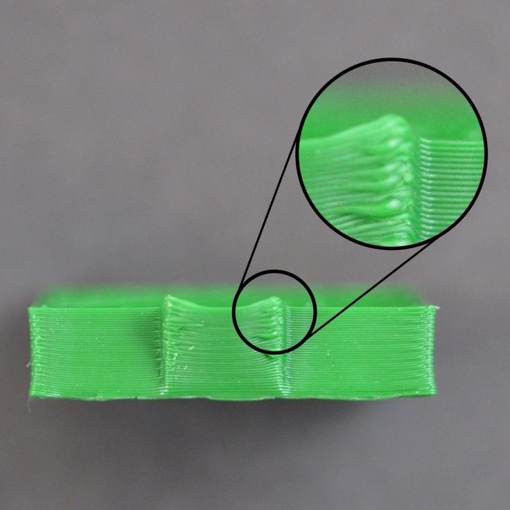 Thankfully, Simplify3D has already provided many pre-configured profiles that can give you a starting point for what retraction speed works best, but the ideal value can vary depending on the material that you are using, so you may want to experiment to see if different speeds decrease the amount of stringing that you see.
Temperature is too high
Once you have checked your retraction settings, the next most common cause for excessive stringing is the extruder temperature. If the temperature is too high, the plastic inside the nozzle will become less viscous and will leak out of the nozzle much more easily. However, if the temperature is too low, the plastic will still be somewhat solid and will have difficulty extruding from the nozzle. If you feel you have the correct retraction settings, but you are still encountering these issues, try decreasing your extruder temperature by 5-10 degrees. This can have a significant impact on the final print quality. You can adjust these settings by clicking “Edit Process Settings” and selecting the Temperature tab. Select your extruder from the list on the left, and then double-click on the temperature setpoint you wish to edit.
Long movements over open spaces
As we discussed above, stringing occurs when the extruder is moving between two different locations, and during that move, plastic starts to ooze out of the nozzle. The length of this movement can have a large impact on how much oozing takes place. Short moves may be quick enough that the plastic does not have time to ooze out of the nozzle. However, long movements are much more likely to create strings. Thankfully, Simplify3D includes an extremely useful feature that can help minimize the length of these movements. The software is smart enough that it can automatically adjust the travel path to make sure that nozzle has a very short distance to travel over an open space. In fact, in many cases, the software may be able to find a travel path that avoids crossing an open space all together! This means that there is no possibility to create a string, because the nozzle will always be on top of the solid plastic and will never travel outside the part. To use this feature, click on the Advanced tab and enable the “Avoid crossing outline for travel movement” option.
Movement Speed
Finally, you may also find that increasing the movement speed of your machine can also reduce the amount of time that the extruder can ooze when moving between parts. You can verify what movement speeds your machine is using by clicking on the Speeds tab of your process settings. The X/Y Axis Movement Speed represents the side-to-side travel speed, and is frequently directly related to the amount of time your extruder spends moving over open air. If your machine can handle moving at higher speeds, you may find that increasing this settings can also reduce stringing between parts.
Related Topics
Problems, defects, 3D printing errors and solutions
Often during the operation of a 3D printer, problems may arise due to which defects appear on the finished model. Or instead of a neat product, plastic noodles suddenly appear on the table.
In fact, the causes of defects can be conditionally divided into 2 types - these are physical and software.
Physical ones are those that arise due to problems with the mechanics or any other causes that can be eliminated physically. These include problems with printer mechanisms (belt tension, backlash), clogged or deformed nozzle, incorrect table geometry, etc.
Software - these are defects that occur due to incorrect slicer settings or, less often, errors in the printer firmware. For example, incorrectly selected print speed, retract settings, incorrectly selected temperature for plastic, etc.
Very rarely, the problem may lie in the wrong or “flying” printer firmware (although usually the printer simply will not start then), overheating of some boards during printing, etc. These are rather special cases, so we will not consider them.
Model peels off or does not stick to the build plate
This is the most common 3D printing problem.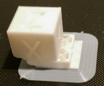 Every 3D printer has had a case when the first layer treacherously rolls, clinging to the extruder, or the most offensive - when it tears off a partially printed model from the table. The first layer must stick tightly otherwise nothing will be printed.
Gap between table and nozzle 9 too large0023
This is the most common reason. You just need to set the correct gap between the table and the nozzle.
Modern printers often use an auto-calibration (auto-leveling) table system or an auxiliary table leveling program. To calibrate such printers, use the instructions. If there is no manual, it can be downloaded from the manufacturer's website.
If you have a simple printer without auto-calibration, a self-assembly or KIT kit, use a probe or a piece of paper folded in half to calibrate. The probe should be slightly pressed against the table by the nozzle. Before calibration, the table and extruder must be heated. Align the table surface over each adjustment screw (there may be 3 or 4) in turn, and only then check the center point.
If you're having trouble getting your table surface perfectly level, try raft printing. Raft is a thick substrate in several layers that is printed under the model. It will help smooth out the slight curvature of the table.
A small cheat sheet to determine the correct gap on the first layer
Plastic with poor adhesion
Some types of plastic, due to various reasons, such as large shrinkage, do not adhere well to the surface of the printing platform. In this case, try using stickers or special 3D adhesives to improve adhesion between the table and the first layer of plastic.
In the early days of 3D printing, there were experiments with different homemade 3D adhesive recipes. ABS diluted in acetone, BF glue, sugar syrup and even beer. Some experiments have been successful. Until now, some enthusiasts use some types of hairspray or glue sticks as 3D glue. But still they are inferior in their properties to industrial 3D adhesives.
Some types of high temperature plastics with a high percentage of shrinkage (ABS, Nylon, etc.) may peel off the table during printing. This is due to uneven cooling and “compression” of the model (the lower layers have already cooled down, but the upper ones have not yet). For such plastics, it is imperative to use a 3D printer with a heated table and a closed case.
Plastic temperature too low
The hotter the plastic is when it exits the nozzle, the better it will adhere to the print platform. It is better to print the first 5-10 layers at a higher temperature (+ 5-10 degrees) and turn off the blower fan.
Wrong first layer settings (speed and thickness)
A thicker layer sticks easier, so the standard first layer is 0.3mm thick. With an increase in print speed, the heating block may simply not have time to heat the plastic to the desired temperature and it will stick to the table worse. Before printing, check the speed and thickness settings of the first layer in the slicer.
A lot depends on how the 3D printer prints the first layer. Try to control the printing of the first layer and only then leave the printer to work alone.
Plastic does not choke from nozzle
The printer has already begun to print, but the print table remains empty. Or part of the model did not print.
Clogged nozzle
In 3D printing, a nozzle is a consumable. The nozzles are clogged or worn out (frequency depends on the type of plastic). The simplest thing is to replace the nozzle. But if there was no spare at hand, you can try to clean the old one. To do this, there is a whole set of thin needles. Or you can heat a clogged nozzle above the melting point of the plastic and “burn out” the blockage. But later it is still better to replace the nozzle.
Low temperature nozzle
You need to increase the temperature of the extruder in the slicer settings or check the thermistor and heating block.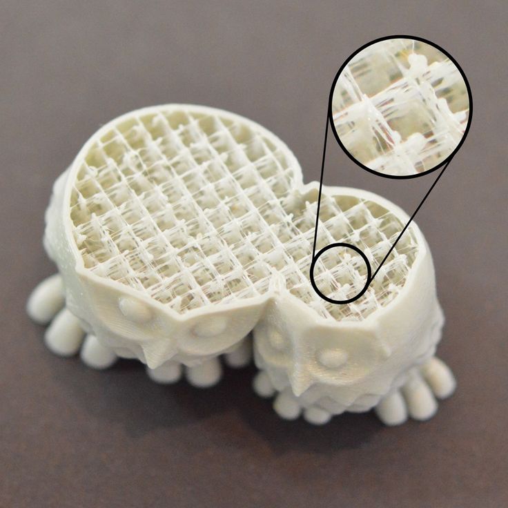 Sometimes the thermistor may not read the temperature correctly due to a malfunction or incorrect 3D printer firmware settings.
If the problem occurs after replacing the thermistor - contact the manufacturer or read articles about PID tuning.
Empty extruder
As the extruder heats up, plastic begins to ooze out of the nozzle. Because of this, the extruder may start printing half empty. Because of this, part of the first layer is not printed. You can push the plastic manually by simply pushing the bar into the nozzle. Or solve this problem programmatically - in the slicer, add a contour print around the model (one line).
Some manufacturers and 3D enthusiasts add a line print on the edge of the table at the beginning of each GCode. This is done so that there is plastic in the nozzle by the time the model is printed.
Feed mechanism does not push through plastic
The plastic pushes the feed mechanism to the extruder - a motor with a special pulley put on the shaft. If for some reason the plastic is not pushed through (nozzle clogged, extruder temperature low, etc.), then the pulley “gnaws” through the bar. You need to push the plastic bar with your hands or cut off the damaged piece.
Elephant foot
The first layers of the model are wider and protrude beyond the boundaries of the model. This is due to the fact that the upper layers put pressure on the first ones that have not yet cooled down and flatten them.
High table temperature
Due to the too high temperature of the table, the lower layers remain soft for a long time. Try lowering the table temperature. It is better to reduce gradually (in increments of 5 degrees). You can try to turn on the blower when printing the first layers.
Small gap between nozzle and platen
If, when printing the first layer, the nozzle is too close to the table, then excess plastic will be forced out. After a few coats, this will not be as noticeable, but can lead to the effect of an “elephant's foot”.
Plastic re-extrusion
When too much material is squeezed out of the nozzle, the walls of the model are not smooth, but bumpy, with sagging.
The solution is software - in the settings of the slicer, you need to set the material feed rate (fluidity) to a lower value. The average value is 95-98%.
It is worth checking the diameter of the rod. If its size is greater than 1.75, then the plastic will be squeezed out more than necessary.
Plastic underextrusion
The plastic is squeezed out too little, because of this, gaps may appear between the layer. The finished model will be fragile and fragile.
Wrong thread diameter
Check the filament diameter in the slicer settings. Sometimes, instead of the popular 1.75, the default is 2.85.
Incorrect feed factor settings
Check the fluidity settings in the slicer. The average should be 95-98%.
Clogged nozzle
Something could get into the nozzle and partially block the exit of the plastic. Visually, the plastic will choke from the nozzle, but in a smaller amount than necessary for printing.
Hairiness or cobwebs on finished model
Thin threads of plastic protrude from the outer wall of the model (most often on one side). The defect appears due to the flow of plastic from the nozzle during idle movement.
Insufficient retract
A retract is a slight pull of a plastic filament from an extruder. Due to the retract when the extruder is idle (from layer to layer or from model to model), heated plastic does not drip from the nozzle. For some flowable plastics (eg PETG) the speed and amount of retraction must be increased.
"Hairiness" can be easily removed by grinding or cutting off the threads with a sharp scalpel.
High temperature extruder
The higher the extruder temperature, the more fluid the plastic becomes.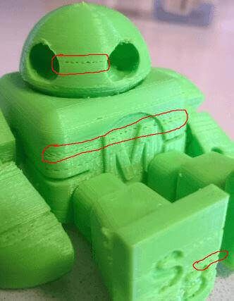 It is important to find a balance so that the plastic is not too liquid and sticks well in layers.
In the selection of the optimal extruder temperature, a test model - a tower - helps a lot. It clearly shows how plastic behaves when printed at different temperatures.
.
Temperature test
Top "perforated" or uneven
The top of the model is bumpy or with holes. The problem may arise if the top of the model is flat. For example, like a cube.
Insufficient airflow
When printing the top plane (cover), the plastic does not have time to cool down and remains too liquid. Because of this, the threads are torn and holes are formed. Increase the fan speed on the last layers.
Few top layers
The top of the print may be too thin and deform as a result. Check slicer settings. The number of upper layers is not recommended to be set less than 6.
Low percentage of filling
If the infill percentage is too low, then the top layer will simply have nothing to rely on. Increase the fill percentage in the slicer settings.
Model deformation
Some parts of the model seem to have melted in some places or on one side. The problem most often occurs when printing with PLA plastic. The defect appears due to the fact that the plastic does not have time to cool and deforms.
Insufficient airflow model
Turn the fans on to maximum. If their power is not enough (in some printers, the fan is located only on one side), you can put a regular desktop fan and direct it to the 3D printer table.
Small model
Small models are difficult to blow well. Try to print small items alongside larger ones, or place several identical models in different corners of the table. So the plastic will have more time to cool.
Layer offset
Layers shift along the x or y axis during printing.
Print head jam
Turn off the printer and try to move the extruder along the x and y axes with your hands. The extruder must move freely. If there are jams, check the mechanics of the printer. Bearing wear or the curvature of the shafts may be to blame.
Electronics overheating
Sometimes electronics problems can be to blame for misaligned layers. The most common cause is overheating of the drivers or too low current exposed to them.
Table top is loose
This is most often seen in 3D printers with glass. During printing, the nozzle may hit the model and move the glass slightly. Before printing, check if the glass or other printing surface is well fixed on the heating table.
Skip layers
Small holes are visible on the print, or the shell of the model is not continuous.
Teflon tube deformed
There are 2 types of thermal barriers - all-metal and with a Teflon tube. If overheated, the Teflon tube may deform. Plastic will pass through it, but in a smaller amount.
Low extruder temperature or high print speed
If the extruder is not heated enough, then the plastic will not be liquid enough and simply will not have time to be forced through the nozzle. The higher the print speed, the higher the extruder temperature should be.
Sometimes the outer walls print well, but the infill is “torn”. In this case, slow down the infill print speed in the slicer.
Model bundle
Cracks form on the surface of the printout during or after printing. Cracks can be large or very small. Most often, this problem occurs with plastics with a high percentage of shrinkage - ABS or Nylon.
Sudden temperature difference (if model delaminates during printing)
With a sharp temperature difference (for example, a draft), part of the model cools down faster. This leads to uneven shrinkage and incorrect distribution of internal stress. For plastics with low shrinkage, this is not critical. But if the shrinkage percentage is more than a few percent, the model may burst in layers.
For printing with such plastics, it is recommended to use a printer with a closed housing. If this is not possible, try to avoid drafts and sudden temperature changes in the room where the 3D printer prints as much as possible.
Print temperature
Due to too low printing temperatures, the layers may not “stick” well to each other. Raise the print temperature in the slicer settings.
Hardening (if the model cracks after printing)
Sometimes cracks appear on the model a few days after printing. This is due to uneven distribution of internal stress after cooling. You can try to “harden” the finished product.
For hardening, the model is placed, for example, in an oven, and heated to the softening temperature of the plastic. After that, the heating is turned off and the oven is left to cool slowly with the model inside.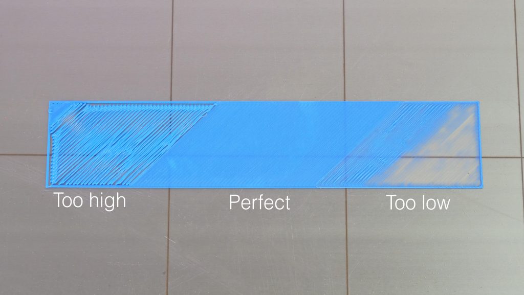 Due to this, the stress inside the print is distributed more evenly. But accuracy is very important in this method - if you make a little mistake with the temperature, the finished product can “float”.
Ringing
In places where the extruder changed direction, ripples are visible. Most often it looks like a shadow around the “sharp” protruding elements of the model.
Mechanical problems
Sometimes the problem occurs due to extruder play. Check if the extruder mount to the rails is loose. Be sure to check the tension of all belts.
High print speed or high accelerations
Moving the extruder too fast can cause vibrations that cause ripples on the wall of the model. The lighter the weight of the extruder, the less noticeable the ripples will be. To get rid of ringing, simply reduce the print speed in the slicer settings.
Slits for thin-walled models (not solid shell)
The thin wall of the model is not solid, but consists of two thin walls with a narrow gap between them.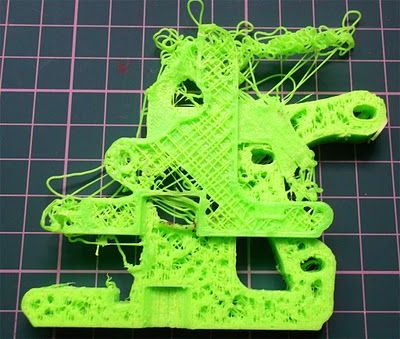 This problem is often faced by fans of printing "cutting" for baking.
Left model with wall defect, right without
Wall thickness and nozzle diameter mismatch
If the wall thickness is 1 mm, and the nozzle diameter is 0.4, it turns out that for a solid wall, 2 nozzle passes are few, and 3 are already many. The result will depend on the slicer algorithm, but most often you will get 2 walls with a thin slot in the middle (the slicer cannot change the wall thickness). The solution to the problem may be a slight refinement of the 3D model or the use of a different slicer.
Algorithms for calculating 3D models are constantly being improved and refined, and now this problem is less common.
When modeling, take into account not only the thickness of the nozzle, but also the percentage of “overlapping” of lines on each other. If you have a nozzle with a diameter of 0.4 - make the wall in your model not 0.
8, but 0.7 - 0.75.
Wrong model geometry
When instead of a circle you get an oval, and instead of a square you get a semblance of a rhombus.
The main reason is malfunctions in the mechanics of the printer. Be sure to check:
Belts
Check belt tension in x and y. Belts stretch over time and may need to be tightened or replaced. Each 3D printer has its own way of tightening the belt. If the belts are slightly stretched, you can tighten them with the help of a "spring".
Loose pulleys, etc.
Check if all bolts and nuts are tight. Are there backlashes. Pay special attention to tightening the pulleys located on the motors along the x and y axes.
Sagging of some parts of the model
Some parts are not printed, broken, or instead of a neat surface, a swollen plastic snot is obtained.
No support for overhangs
A 3D printer cannot print in the air, so if there are overhanging elements in the model, you need to set supports - supports. The slicer can set the necessary support itself, you need to check the appropriate box in the settings.
When printing with soluble support, you can set the gap between the model and support - 0. This will make the surface smoother. If the support material and the model are the same, you need to add a small gap. Otherwise, it will be difficult to separate the support from the model.
Split model
Sometimes the supports can take more plastic than the model. In this case, to save material and time, it will be more convenient to cut the model. If you have more than one 3D printer, then the model will print several times faster.
When cutting the model, you can leave grooves or mortgages so that the pieces of the model are connected without displacement.
Totals
In this article, we talked about the most popular 3D printing defects and how to solve them. Don't be intimidated by such a long list. Some problems are rare and you are unlikely to encounter them.
There is a list of problems that arise due to the design features of a 3D printer, so try to choose a printer that suits your needs. To do this, you need to understand what products and what material you need.
Problems associated with printing algorithms are quickly eliminated by software developers.
Do not be afraid of possible difficulties and each seal will be successful.
20 Most Common 3D Printing Problems (Part 1)
Good afternoon dear 3D Today community! I would like to present you a translation of the article Troubleshooting Guide to 20 Common 3D Printing Problems, which will be divided into 2 parts.
Everyone has problems with printing. We had enough of them to analyze and find solutions for the 20 most common 3D printing problems. In this article, we share our experience and hope that now you do not have to spend extra time diagnosing and solving problems that have arisen.
If you cannot determine what the problem is, compare it with the description.
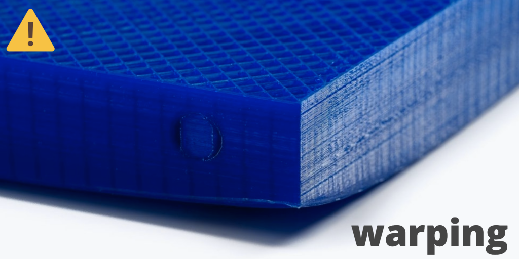
3D Printing Issue #1: Warp - First Layer Peeling
Description of Issue
At the base of the model, the print rises and does not stick to the platform. This problem can also cause horizontal cracks in the top sections of the printout.
Why did the problem occur?
Deformation of the print base is due to the nature of the plastic. ABS and PLA plastic cools very quickly and this is what can cause the first layer to come off.
Solve 3D printing problem: Printout warped
1. Use heated bed. The easiest solution to this problem is to use a heatbed and set the temperature just below the melting temperature of the plastic. If you set the temperature correctly, the first layer will not come off the platform. The printer bed temperature is often set automatically by the slicer. The recommended temperature for your plastic is listed on the side of the package or reel.
2. Use adhesive . If your printout is lifting around the edges, apply a thin layer of glue (or hairspray) to the platform to increase adhesion.
3. Try another platform. Change the platform to a platform with more adhesion. Manufacturers like Lulzbot use a PEI (Polyetherimide) coating that provides a good grip even without the use of glue. XYZPrinting Some printers include a few pieces of thermal tape for the liner. This is a good solution for cool platforms. Zortrax 3D choose a different solution - a perforated backing to which the printout adheres, thereby relieving the user of the problem of deformation at the base.
4. Calibrate the platform. Improper platform calibration can also affect the print quality of the first layer. Check the level of the platform and correct the height if necessary.
5. Increase contact between printout and platform.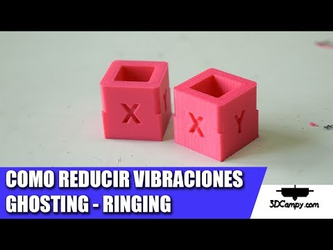 Often this problem also occurs due to insufficient contact between the model and the substrate. It can be easily corrected using the printer software by adding a skirt or backing.
6. Optimize temperature settings. If none of the methods worked, check the advanced settings of the printer software and the printer itself. Try increasing the platform temperature by 5 degrees.
7. Pay attention to the fan settings. As a general rule, the fans should switch to full power as soon as the print reaches a height of 0.5 millimeters, but you can increase the height to 0.75 millimeters to allow the layers to cool naturally.
8. Even if your printer has a heated bed, it is recommended that you use glue (or varnish) and constantly adjust the bed level.
3D Print Warp: Checklist to Avoid Problems
- Use Heated Platform
- Use Glue (Varnish) for More Adhesion
- Instead of Glass Platform, Use Kapton/Heat Tape/Glue/Varnish
- Recalibrate Platform or substrate
- Adjust temperature and fan settings
3D printing issue #2: First layer misalignment (Elephant's foot)
Problem description
The base of the model is slightly off.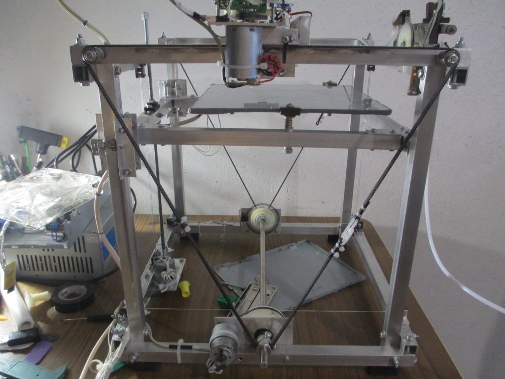
Why did the problem occur?
Typically, the base of the model is shifted due to the weight of the print, which presses on the first layer when the lower layers have not yet had time to cool. Often happens with heated bed printers.
3D Printing Solution: First Layer Offset
1. Correct balance. In order to get rid of the problem of first layer displacement, printed models must be sufficiently cooled to support the weight of the entire structure. Here you should be careful: excessive hypothermia can lead to deformation of the first layer. Finding a balance is hard enough. Start by lowering the platform temperature 5 degrees (but no more than 20 degrees below the recommended temperature). If Bottom / Top Thickness is set to 0.6 millimeters, turn on the fan immediately at a height slightly lower.
2. Platform level. Most 3D printing problems are related to the wrong platform level. For each printer, there is a specific approach for platform level calibration. Check the manufacturer's recommendations to determine what you need. Print out a calibration cube and look at the quality of the plastic feed. The calibration cube will help you determine if the plastic has been laid flat, and if the nozzle is too close to the platform and scrapes the melted plastic, or too high causing the plastic to bubble.
3. Raise the nozzle. Raising the nozzle a little can often help. The main thing is not to raise it too high.
4. Smoothen the corners of the model. If all else fails, try chamfering the corners of the model base. Of course, this is only possible if you created the model yourself or if you have access to the source file. Start with 5mm and 45º bevel and experiment to get the best result.
First Layer Offset in 3D Printing: Checklist to Avoid Problems
- Balance Platform Temperature and Fan Speed
- Raise Printer Platform
- Check Floor Height
- Make model corners smoother
Description of the problem
The first layer does not look right, some fragments are missing. There are unnecessary lines at the bottom.
Why did the problem occur?
Such 3D printing problems usually indicate that the platform level has not been set correctly. If the nozzle is too far from the platform, unnecessary lines often appear at the bottom of the printout or the first layer does not stick. If the nozzle is too close to the platform, this can cause formation bubbling.
Also note that the platform must be clean. Fingerprints on the platform may cause the first layer to not adhere to the platform.
3D printing problem solution: Other first layer problems
1. Set the platform level. Each printer has its own platform level configuration process. For example, the latest Lulzbots use auto-calibration, while Ultimaker offers step-by-step manual calibration. But to set up the Prusa i3 platform level, you will need to spend a lot of time studying the issue.
2. Set nozzle height. If the nozzle is too high, the plastic will not stick to the platform, if it is too low, the nozzle will scrape the printout.
3. Clean the platform. Be sure to clean the printer platform regularly, especially if you are using adhesive. Fingerprints, dust and adhesive residue affect how well the model sticks to the platform.
4. Use glue (varnish). Apply a thin layer of adhesive to the platform to increase the adhesion of the model to the platform. Remember to clean the platform regularly as excess glue can cause the opposite effect.
Layers shift in the middle of the printout.
The printer straps are not tight enough. The top plate is not attached and moves independently of the bottom plate. One of the rods in the Z-axis is not perfectly aligned
Solution to 3D printing problem: Misaligned layers in the model
1. Check the belts. First of all, check how tight the straps are: they shouldn't hang loose, but they shouldn't be too tight either. If you pull on the straps, you should feel a slight resistance. If you feel that the top strap is tighter than the bottom strap, this is a sure sign that they are not tight enough.
2. Check the cover. Check the cover, rods and other parts on top of the printer (if you have coreXY). Make sure all parts are properly fastened.
3. Check the z-axis screws. Many printer manufacturers use threaded studs more often than trapezoid screws, and while both do the job, the studs tend to bend over time. No need to disassemble the printer to check if the rods are straight. Simply use software such as Printrun to move the print head up and down. If one of the Z axis bars is bent, you will definitely notice it. Unfortunately, it is almost impossible to straighten a bent stud, but on the other hand, this is a great reason to replace old threaded rods with trapezoidal screws.
Supreme displacement: Checklist
- Check belts tension
- Check if the upper lid is
- Make sure that the hairpins along the zis are even
The description of 3D 9,000 9: the absent layers of 9000 9000: the absent layers of 9000 9000: the absent layers 9000: problems
Gaps in the model appear due to the fact that some layers are missing (partially or completely).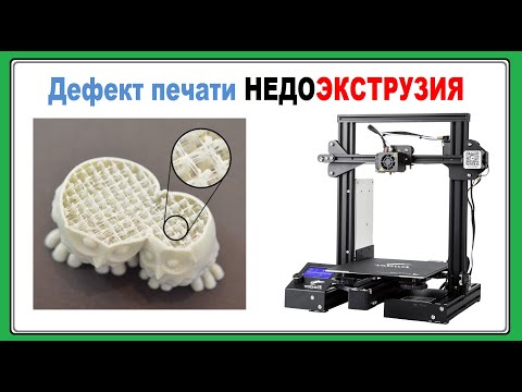
The printer was unable to produce the required amount of plastic to print the missing layers. In 3D printing, this problem is also known as under-extruding. The essence of the problem may lie in the plastic itself (for example, a different diameter of the material), in the coil, in the feed mechanism (extruder) or in a clogged nozzle.
Friction can cause plastic to get stuck. It could also be that the z-axis screws (studs) are not properly aligned with the linear bearings.
There may also be a problem with screws (studs) in the Z axis and with the bearings themselves.
3D Printing Solution: Missing Layers
1. Mechanical Check . If suddenly you find missing layers in the print - it's time to take a little care of your printer. Start by checking the screws (studs) and make sure they are firmly attached to the bearings or clamps.
2. Check rod alignment. Check that all screws (studs) are aligned and not misaligned. Turn off the power and gently move the print head along the X and Y axes. If there is any resistance, then there is some problem. It is easy enough to understand what exactly the problem lies in - a slightly bent rod or bearings.
3. Worn bearings. Worn bearings make noise. You may also feel the rattle of the print head, while the printer vibrates slightly. In this case, turn off the power and move the print head along the X and Y axes to find out where the worn bearing is.
4. Check the oil. Remember to regularly lubricate the moving parts of the printer. Sewing machine oil is ideal for lubrication - you can buy it at any hardware store at an affordable price. Before applying oil, make sure the studs (screws) are clean. If the studs(screws) have dirt or print material residue, clean them.
Then connect to the printer via a program (eg Pronterface) to move the print head in the X and Y axes and check that the studs are evenly lubricated. If you apply a little more oil, just wipe off the excess.
5. Underextruded . The last cause of the problem may be insufficient extrusion. There can be many solutions to this problem, and all of them are described in Section 9.
Checklist
- Check the printer mechanism to make sure the moving parts are tight.
- Recheck printer design and alignment
- Check for worn bearings and bent pins
- Use some oil to lubricate parts
3D printing issue #6: Cracks in tall objects
Problem description
Cracks on the sides of the model, most commonly in tall models.
The problem can occur unexpectedly, and most often occurs in large printers, especially if you do not monitor their work.
On the upper layers, the material cools faster because the heat from the platform does not reach the required height. Because of this, the adhesion of the upper layers is lower.
3D Printing Solution: Cracks in Tall Objects
1. Extruder Temperature . Start by increasing the extruder temperature - 5-10ºC is best. On the side of the plastic box you will find the highest temperature for plastic, try not to raise the temperature to this value.
2. Fan direction and speed . Double check your fans and make sure they are pointed at the model. If the direction is correct, reduce their speed.
Checklist
- Check the maximum possible temperature of the extruder and increase the current temperature by 10ºC in one attempt.
- Check the direction and speed of the cooling fans.
3D Printing Issue #7: Holes in the top layer
Description of the issue
Holes and gaps in the top surface of the printout.
The two most common causes of this problem are improper top coat cooling and top coat not thick enough.
Solution to 3D printing problem: Holes on the top layer
1. Filament diameter . Often the problem happens with plastic with a diameter of 1.75 mm. Holes in the top layer are a problem with all 3D printers, but they happen more often with printers that use 1.75mm filament than with printers that print with filament larger than 2.85mm.
2. Check the location of the fan . Cooling can cause this problem, so check the fans first. When the printer starts printing, the fans are at their lowest speed or off. After printing the first layer, the fans start to work. Check if they start working and also check if they continue working when printing is finished. If all is well, double-check if the direction of the fan is set correctly - they should blow over the model.
3. Set fan speed in G-Code. Another cooling issue is related to excessive plastic in the top layer. It must cool quickly so as not to fall between the already printed supporting elements. The fan speed can be adjusted with G-Code ( is usually G-Code for Fan On is M106 and M107 Fan Off ). Also set the fan speed to maximum for the upper layers.
For example, for a 1cm x 1cm cube, the height of the top layer would be 0.1mm. In this case, when generating a G-code through CURA for Prusa i3, the G-code indicates that the number of layers for the cube is 100. Considering that we specified heights of 0.6 mm for the top and bottom layers, it is worth editing the value to LAYER: 94
4. Increase the thickness of the top layer . One of the simplest solutions to the problem is to increase the thickness of the top layer. In most applications, you will be able to adjust the thickness using the ‘Bottom / Top Thickness setting’ advanced settings. You need to increase the thickness of the top and bottom layers up to 6 times the other layers and up to 8 times for smaller nozzles and plastics. If the layer height is 0.1mm, then the height of the top and bottom layers should be 0.6mm. If there are still holes and bald spots in the top layer, increase the thickness to 0. 8mm.
8mm.
Cheklist:
- Use a larger diameter
- Make sure that the direction and speed of the fans are correct
- Manually set the fan speed
- Enlarge the thickness of the upper layer
- Check the diameter of the Philiment
- Use the caliper diameter
- Check whether
- EXTRITITIONS by 5% of
problem.
Description of the problem
Cobwebs or hairs appear between model elements when printing.
When the printer head moves over an open surface (without extrusion), i.e. from one object to another, the plastic flows out of the nozzle.
3D printing solution: Hairs, webs
1. Turn on retract . Retraction is an important factor for the quality of the finished model and can be enabled in the slicer. It functions quite simply and works by pulling the filament back into the nozzle before the head starts to move. The bottom line is that it prevents plastic from flowing out of the nozzle, which creates a "spider web" between objects.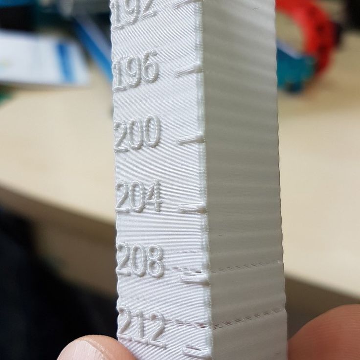
2. Retraction activation in settings . Most apps like Cura offer pull activation in settings and this is set by default. However, if you want more options, you can customize them further. For example, you can set the minimum head path before activating retraction.
3. Minimum distance (mm) . If retraction is not working correctly, the easiest way to fix this is to reduce the minimum distance. Reduce it by 0.5mm until hairiness disappears. Activate retraction (retract) to increase the speed of printing.
This problem has several causes. First of all, the thread diameter may not match the diameter set in the slicer. Also, the amount of extruded material may be lower due to incorrectly configured firmware. Another problem is that the nozzle can become clogged and this will cause under extrusion.
3D Printing Solution: Underextruding
1. Check filament diameter . Start with the simplest solution - check the filament diameter settings in your slicer. If you are not sure about the filament diameter and the recommended temperature, check the information on the packaging.
2. Measure thread . If you still can't get the desired result and filament separation remains a problem, use a caliper to check the filament diameter. After measurement, adjust the settings of the slicing software. ( author's note - if you have a bowden hotend, then you need to unscrew the fitting from the hotend, enter the command (for example, in Pronterface) M302 : Allow cold extrudes and extrude a meter of plastic. If more or less is extruded, then you have an incorrect number steps per mm for the extruder If you have a direct hotend, then you need to unscrew the nozzle ( the nozzle can only be unscrewed when it is hot! ). It is also worth noting that even with the correctly set steps per mm value, when retracting, the distance traveled will be less than when extruding. This is because more resistance is experienced when retracting )
3. Check print head . After starting printing, most printers lift the print head off the model base. Check if the nozzle is clean.
4. Set the extrusion factor to . If there is no difference between the actual extrusion diameter and the software settings, check the extrusion multiplier settings (or flow rate or flow compensation), they may be too low. Each slicing application solves the problem differently, but try increasing the ratio by 5% and restarting the print process.
5. Open the Edit Process Settings window in Simplify3D and go to the Extruder tab - the extrusion factor should be set to 1.0 which corresponds to 100%. Open the Material tab in Cura and increase the Flow settings (you may need to enable Flow in the Preferences window).
Cheklist:
Description of the problem
Excessive extrusion means that the printer is supplying more material than needed.