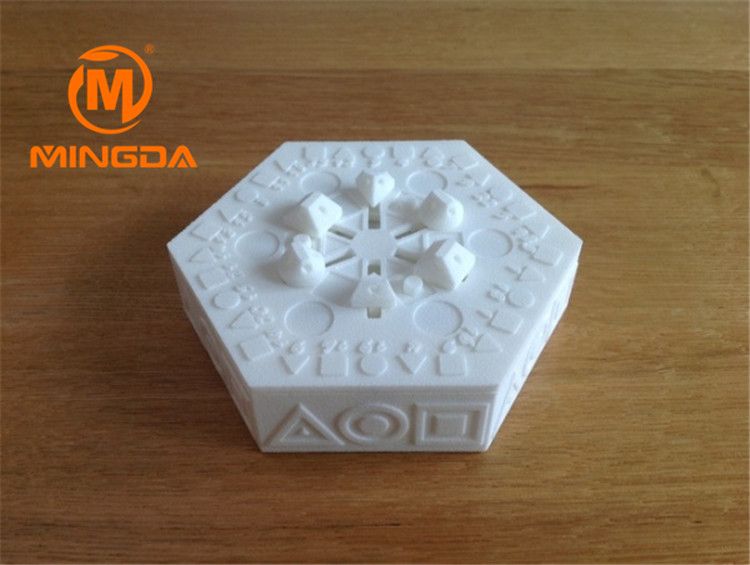
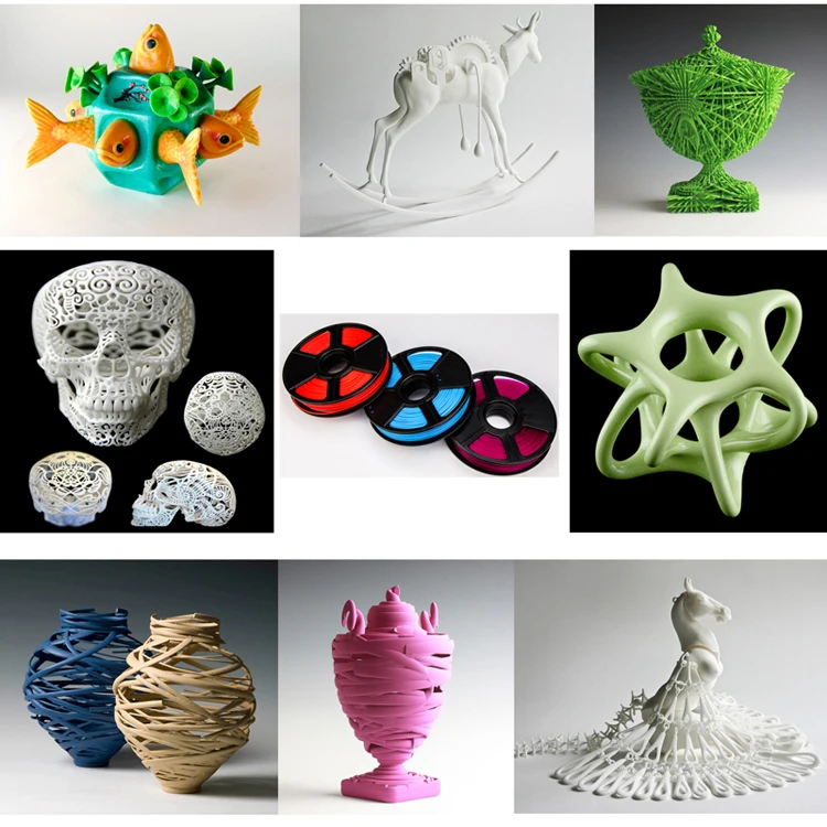
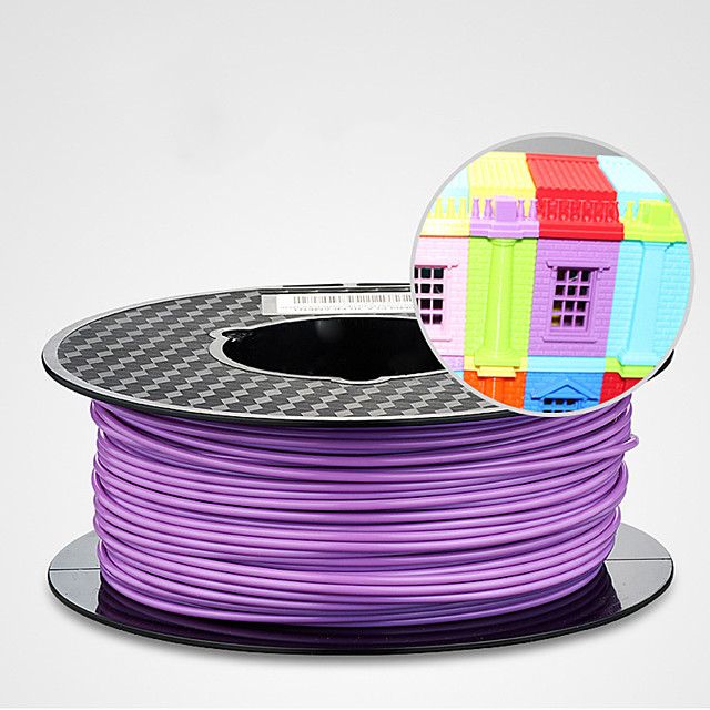
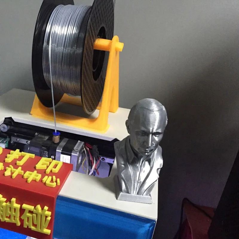
3D printer paper filament
Paper 3D Printing: The Complete Guide
Paper 3D printing might not change the world, but it could be the fun, accessible technology that pushes 3D printing into the mainstream.
Producing customizable, colorful toys and models is one way in which paper 3D printing can enrich our lives, but paper can also be used to create full color prototypes and models for architecture and other uses.
The Science Behind Paper 3D Printing
Paper 3D printing may seem strange in theory. As a material that burns easily, more common methods of 3D printing such as FDM or SLS are an impossibility. What’s more, unless you are skilled with your hands, paper is extremely difficult to manipulate. Forming paper into complex structures is a near impossibility.
That is where we introduce Dutch engineer Beer Holthuis. A graduate of the Design Academy Eindhoven, Beer observed two things: our enormous amount of paper waste, and the lack of recyclable materials used in 3D printing.
Across the world, around 80 kilograms of paper and paperboard is used annually per person. Additionally, 3D printing’s development has not yet reached a stage where environmentally friendly materials are widespread. Bar PLA, most plastic filaments are not biodegradable, and rarely made from recycled sources.
In the earliest stages of paper 3D printing, reusable molds were manufactured with plastic to produce 3D parts using paper pulp. Beer, however, is among the first to pioneer new methods of 3D printing entirely using paper, of which there are a number of similar, yet distinct, techniques.
Paper 3D Printing Technologies
Laminated Object Manufacturing (LOM)
LOM is the primary technology leading the drive towards mainstream adoption of paper 3D printing, and it is the technique capitalized upon by Beer Holthuis.
LOM was first invented, however, by Cubic Technologies (then called Helisys Inc). The process involves depositing individual layers of adhesive-treated paper material onto the printer’s build plate, which is then laminated with a heat roller. The layers are then all glued together, before a laser or blade cuts out the desired geometry for the shape to produce a finished part.
While the technique can also be used for plastic and metal, here paper is soaked in adhesive to allow layers to form and make the gluing process easier. Beer has improved the technology by using recycled paper pulp suspended in resin that is deposited to form the layers. Not only does this make paper 3D printing more environmentally friendly, but also makes the process much quicker.
The LOM process for 3D printing paper prototypes.Selective Deposition Lamination
Though SDL also uses a laser to cut shapes into paper, this method differs slightly. Where LOM glues all layers together and cuts shapes from that block, SDL cuts during the production of each layer, then laminates those. It was invented in 2003 by brothers Conor and Fintan MacCormack, and was designed to drastically lower to operating costs of expensive competitors at the time.
A technique used today by companies such as Clean Green 3D, this not only reduces the amount of energy waste by streamlining the lamination stage, but also allows for not just full color, but multicolor production, one of the biggest benefits working in paper 3D printing’s favor.
These intricacies do add to production time; Clean Green 3D say that their CG-1 printers are able to produce 3D models that are recyclable, tactile and biodegradable, making this sector the cleanest in the industry.
If you are looking for a paper 3D printer for rapid prototyping, we may be able to help:
Get a quote*
*One of our trusted partners will be in touch following a quote request.
Paper 3D Printing Applications
Prototypes and Architectural Models
While 3D printing in general is a largely a prototyping technology, LOM and SDL are among the most effective at this. Paper 3D printing allows companies from a range of different industries to quickly, cleanly, cheaply and repeatedly craft product prototypes to visualize a final design in physical form. Traditional manufacturing methods simply cannot compete.
Unlike what would be expected, these paper models are surprisingly robust. While paper 3D printing has few practical industrial applications, prototypes can withstand a respectable amount of strain, and paper 3D prints have been used as tools, furniture, or even architectural models.
Paper 3D models are a drastically cheaper alternative than the plastic or metal models used previously, and allow architects to present a more substantial and tactile image to their clients as opposed to the currently widespread use of Virtual Reality. Everything from houses to skyscrapers are possible.
With product development a major cost factor for companies, paper 3D printing is announcing itself as a useful technology in reducing the costly waste that this entails. 3D printed paper prototypes are the cleanest and most cost-efficient choices for the job.
Geological Models
Paper 3D printing has a number of benefits that make geological mapping and wildlife conservation easier than ever before. With these techniques, 3D models of terrain can be accurately produced which are far easier to understand than a 2D map or even a computer model.
Moreover, with the ability to add color, conservationists are able to plot not only altitude, but species movement, weather, foliage and topography, making route planning and equipment preparation simpler, and reducing transport costs and unnecessary luggage.
Toys and Minifigures
On a more jovial note, paper 3D printing is a perfect way of making a range of toys, figurines and gaming components that can add a touch of personalization to any gaming session.
Whether it be action figures or accessories for children, safe playthings that won’t shatter like plastic can, or even miniatures for use in board games, paper 3D printing can create something unique and vibrant.
This also has the added benefit of increasing customization options for color and design. Making a lookalike Dungeons and Dragons avatar but with rippling muscles and a giant sword is a dream for any gamer, and can add a touch of reality to immerse yourself in.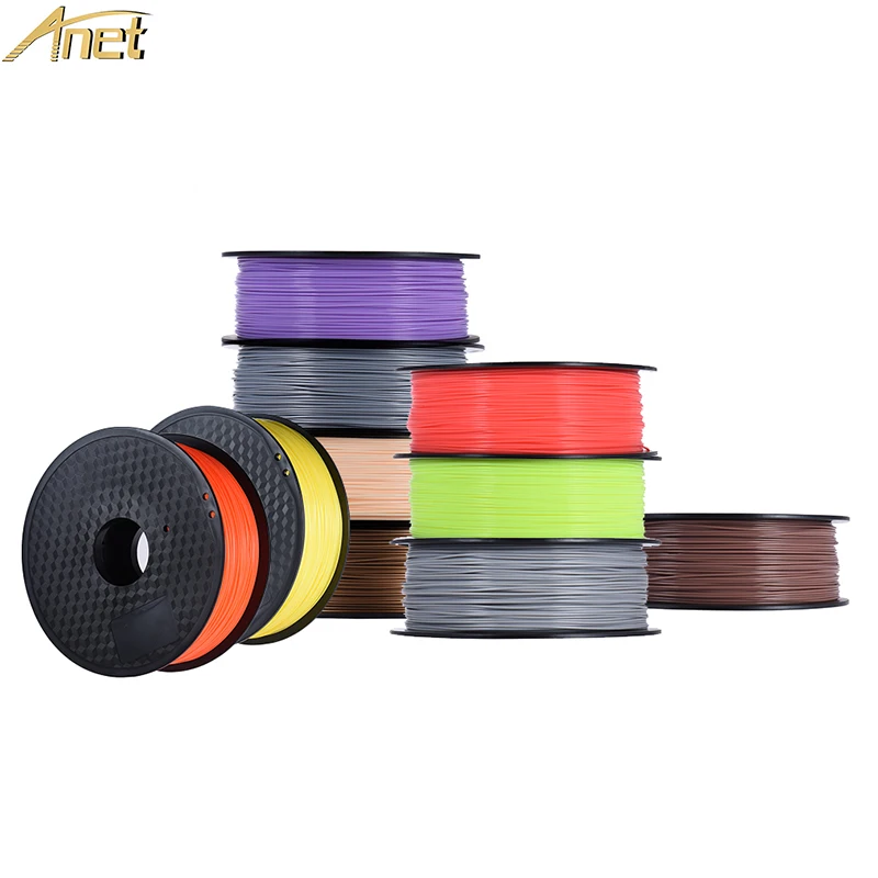
See also: Our list of the best 3D printers for miniatures.
Part 3: The Pros and Cons of Paper 3D Printing
Pros
Cheap
Almost every aspect of paper 3D printing is cheaper than any alternative you’ll find, at about 5% the cost per volume of standard 3D printers. The paper material is cheaper than plastic or metal filaments and the energy costs are lower due to the reduction in heating, using only a heat roller and laser as opposed to melting plastic or metal. This makes it one of the most cost-efficient 3D printing technologies on the market today.
Color Customization
Perhaps the most unique aspect of paper 3D printing is that there is infinite customizability with color. No other 3D printing method has a comparable level of flexibility in design.
Not only can paper be dyed to custom produce parts based on preference, but with SDL, colors can be changed between layers, with full color models that will bring any design to life. Depending on the product, either LOM or SDL will fulfill your needs.
Environmentally Friendly
Again, being set apart from other 3D printable filaments, paper 3D printing supports the use of recyclable and biodegradable material. Paper 3D printing also doesn’t involve much heating, saving energy and making it one of the cleanest methods around.
Cons
Lack of Applications
Despite the fact that 3D printed paper products are surprisingly robust and impact resistant, the biggest drawback is that there are few practical applications in which paper is a good choice.
It is biodegradable, which is helpful in being environmentally friendly, but also means that paper parts decay quicker than other materials making it less useful in industries like construction. Its weak parts are easily crushed and are therefore better suited to aesthetic prototypes rather than practical tools.
Lack of Precision
The nature of using blades and lasers to cut layers into shape means that the level of complexity possible with these techniques is drastically lowered. This means that prototypes or models with intricate designs and edges are much more difficult to produce. For producing prototypes with more complexity, using plastics or metals will produce much better results.
Conclusion: How Useful Can Paper 3D Printing Be?
Paper 3D printing has already proven useful in certain situations, but paper’s issues have hindered development. If the structural issues can be fixed, paper could be used far more in industry.
If the limitations of the design complexity can be diminished, many internal mechanical components such as cogs and pulleys can be manufactured as replacements much more quickly and cheaply. These parts experience very little stress and therefore a paper alternative would be not be required to withstand any great force. The main prohibiting factor is that these parts can often be small, with intricate edges, something that is not possible with paper at the moment.
Additionally, while paper does degrade at faster rates than plastic or metal, replacement costs will be low enough that this issue does not bear any real consequences.
The lack of strength is also a hinderance, but one that can only be managed rather than eradicated. Paper is not strong, and while post-processing treatments can help, it will never be strong enough to have industrial applications.
One interesting avenue in which paper is finding some use is fashion. Research has been conducted to explore 3D printing technology in general as a means to achieving zero emissions in the fashion and jewelry industry, and other experts have claimed that using paper 3D printing would be a benefit by rapidly and cleanly producing garment prototypes.
See also: our deep dive into the world of 3D printed fashion.
With paper 3D printing continuing to develop, perhaps it won’t be long until we see its fun and colorful potential arrive in our homes.
The Paper Pulp Printer replaces plastic with paper waste
Published on November 9, 2018 by Michelle J.
The market for Additive manufacturing is constantly growing in everything from the automotive industry to ceramics. However the biggest part is still in more traditional areas like prototyping using plastics. While 3D printing do bring advantages such as being faster and less wasteful than traditional manufacturing, also making it easier to produce on demand. The problem is that the majority of print material used is still plastic, which is one of the most harmful materials for the environment.
This became apparent for designer Beer Holthuis as well, who wondered why there isn’t more sustainable materials for 3D printing. This has led him to develop a method to print with sopping wet paper. The Paper Pulp Printer, is the world’s first 3D printer using paper pulp to replace plastic. Generally the market of materials is growing and there are other alternative materials you can choose from for your prints. However most other are still hybrid materials using PLA as a base.
Beer Holthuis 3D prints with paper waste
Beer Holthuis, from the netherlands, is as a product designer. In this regard, he has crossed path with 3D modeling and additive manufacturing.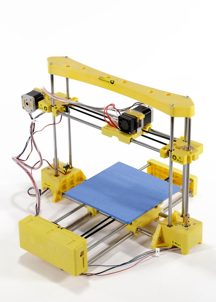 Through this process, he noticed the worrying amount of plastic being used in the process and started searching for a more sustainable material to replace it.
As the amount of paper waste per person is at around 80 kg yearly, he decided to work with this wasteful and hugely used material. Unlike earlier paper printing techniques such as the 3D printing technology from Mcor, Beer wanted to print directly with the waste material itself. Giving us the world’s first 3D printer to print pulp.
A paper pulp printed speaker
How the Paper Pulp Printer works
The printer itself are currently pretty straight forward and works overall similar to other 3D printers. For the material he takes regular paper pulp in combination with a natural binder to keep it together. That the binder itself is a natural material as well means that the 3D printed products can continuously be recycled. This creates a closed loop system making it very sustainable long term. He then basically extrudes the paper material through a syringe type extruder from a pressure vessel.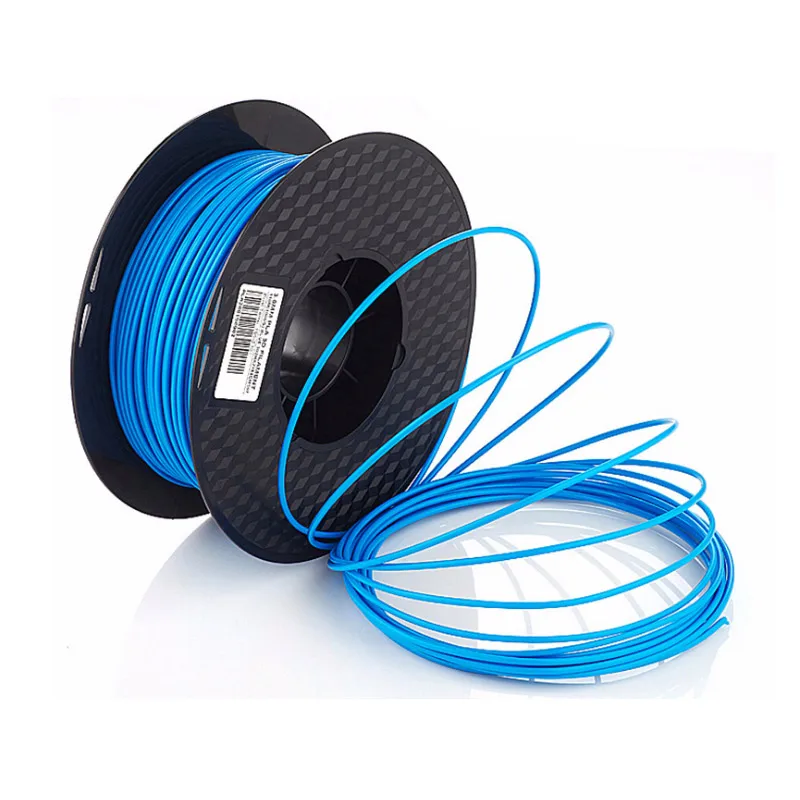 The main issue lies with when the printer stops and possible problems with how to keep it from gunking up.
The aesthetics of Paper Pulp Printing
The overall look coming out from the Paper Pulp Printer and texture it produces stands out on it’s own. As Beer Holthuis himself explains, “The design of the printed objects are using the possibilities and beauty of this technique,” And he continues, “The tactile experience, bold lines and print speed results in distinctive shapes. The objects are also durable: Printed paper is surprisingly strong.” The special look of the print gives the designs a bit of personality, bringing something extra to the table.
With everything being low cost in combination with the sustainable aspect there are future potential. This recycling system should be able to take off and work on a high production level.
If you want to see the printer in action, check out the video below:
What to you think of this 3D Paper Pulp Printer? Let us know in a comment below or on our Facebook and Twitter pages! And remember to sign up for our free weekly Newsletter, to get all the latest news in 3D printing send straight to your inbox!
Paper 3D printer AKNT i3
Paper 3 d printer AKNT i3
The work on the Paper 3d printer was started at the amateur radio circle of the Almaty State College of New Technologies (hereinafter AKNT College) after reading the article “3d printer for $ 60” . After reading the article, it was decided to start work, especially since several of the necessary stepper motors, Arduino Mega were already available. While studying the topic of making 3d printers, there was a desire to make the printer more serious, with a larger print area. Such a printer was needed for our robotics circle, for the manufacture of various parts for projects.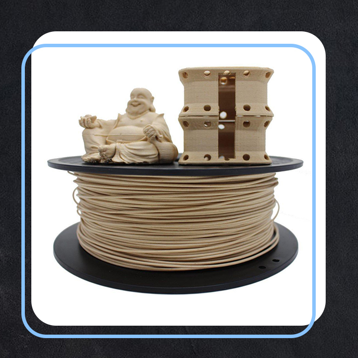 Of course, there were no funds to purchase a new printer, even a ready-made kit. Therefore, college students and I tried to make our own printer and meet $60 (in the future, expenses will be calculated in dollars). It was decided to order only an extruder (printer print head), a bowden (filament feeder), two meters of belt, two rollers, a set of linear bearings, a Ramps 1.4 board with drivers and a display, a heating table from Aliexpress (cost $ 50). And the rest of the parts for the printer were selected separately.
1Details of a 3d printer from Aliexpress
Almost all Mendel, Prusa i3 projects available on the Internet required to have another 3d printer for printing body parts, or order them from third-party organizations specializing in printing 3d models, which required another $ 30-50 ( in Almaty, an hour of printing costs about $5). Therefore, having gone through all the possible options, we decided to implement the RepRap technology, that is, to create a 3d printer from cheap materials, which in the future will be able to print the necessary body parts for itself (its upgrade).
On the GrabCad website, a design for a 3d printer body was found that does not require printing of parts. Having finalized this project in the AutoCad program, according to the thickness of the existing material - a piece of MDF (pressed paper) and made the necessary changes to some details of the drawing, all the developments were sent to an advertising agency (the cut cost $ 10). A week later, we received a lot of paper parts, which we adjusted with the guys for a few more days. The result of this work was the "paper" frame of the printer (Fig. 3)
Also in the college there were two unused inkjet printers and two scanners - sources of guides, however, as a result of disassembly, 3 guides for 8mm and 1 guide with a diameter of 7mm were obtained, which found their use in the Z and X axes. decided to use ball bearing furniture rails (courtesy of the college furniture shop). Stepper motors were originally planned to be used from printers and scanners, but they were different and there was a problem of fastening the rollers. In this regard, it was decided to investigate all the faulty equipment available in the college and the motors were found in the DMX lighting fixtures.
Two 8mm guides from printers were mounted on the Z axis, and guides from scanners were mounted on the X axis to mount the extruder. The 7 mm guide (due to the smaller diameter) was fixed with fluoroplastic bushings. The standard LM8MM bearings used in budget printers were lost in the vastness of vast China, and in order not to waste time waiting for a second shipment, the extruder mount was made from two scanning heads of scanners, the bearings of which are copper bushings pressed into the plastic body of the head. Having cut out fasteners with copper bushings from each scanning head, they installed them on the corresponding X-rails and glued them together. The result is a fairly strong extruder mount with good sliding along the X axis.
The package with the aluminum filament feeder and the E3D extruder was one of the first to arrive, so by the time of assembly it was already ready. It was decided to abandon the Teflon (PTFE) tube that comes with the extruder and connect the extruder to the filament feeder directly through an adapter machined in the college's turning shop. The result is the following satisfactory construction.
Since the belts and rollers were lost along with the bearings and were re-ordered, belts from scanners were found in the printer, which use a belt with a 2mm pitch, similar to GT2, only thinner and a little short for the X axis. Therefore, instead of a standard bypass bearing, a bypass roller with a metal mount from the scanner is installed.
M6 threaded stud, 80 mm long, found in the furniture shop of the college. Initially, furniture ties with M6 internal thread, drilled with a 5 mm drill for the motor rod, were used as couplings for studs with a stepper motor. Despite the imbalance due to these sleeves, sleeves made of PLA plastic were later printed.
Initially, the heating table was planned to be installed on the 3-way furniture rails available, but open access to the bearing balls did not inspire confidence, so it was decided to turn the rails over, fix the table to its main part (base), and fix the middle part to body of the 3d printer using steel corners, the third part of the guide is removed along with the balls.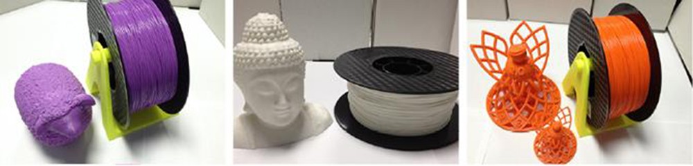 The main disadvantage of such guides is the sound, it can be assessed by ear when the table is moved quickly - unpleasant squeaks of the movement of the balls were emitted. In this connection, when linear bearings appeared, “handicraft” guides were replaced with classic ones used in all ready-made 3d printers.
As end sensors, we chose a circuit based on optical sensors soldered on breadboards. The diagram and photographs are shown in the figures below. On the Z axis, the distance between the table and the print head was calibrated by screwing in the adjusting screw. Along the Y axis, the sensor is mounted on an aluminum corner and fixed to the rear wall.
9
In the process of creating a printer, one of the biggest difficulties was to achieve high-quality printing from the print head (extruder), there were constantly plugs in the filament supply and marriage turned out. The ordered E3D V6 extruder kit turned out to be of poor quality. The steel thermal barrier does not have a Teflon sleeve, the fan and the radiator did not provide proper cooling. As a result, it was not possible to get even a fully printed test part, the thread became thinner or simply stopped feeding. Attempts were made to create their own thermal barrier from a drilled M6 bolt and an inserted piece of Teflon tube, which was installed in the radiator from the amplifier or in the aluminum supply block of the supply part.
In the end, a high-quality E3D V5 extruder kit was purchased at the Karaganda RadioMart store for $ 14. After installation, all printing problems were resolved. In the Compass 3d program, an extruder attachment model was developed, which was printed using a high-quality thermal barrier. Therefore, advice to beginners - choose an extruder with a terbobarrier with a Teflon insert, or order a spare thermal barrier from the seller, my savings of $ 5-7 resulted in the loss of a large amount of time and a bad mood. The 3d model of the extruder mount and its appearance are shown in the figures.
As soon as the 3d printer started printing, significant shortcomings of the inexpensive paper construction (MDF) were revealed - the layers did not overlap evenly due to the insufficiently elastic construction, frame twitches were felt during printing, etc.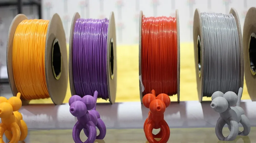 Therefore, they began to refine and strengthen the entire structure. Firstly, all the details of the X axis were printed with PLA plastic. The belts from the scanners have been replaced with a GT2 belt, bypass bearings have been installed. Furniture guides were dismantled and replaced with guides with linear bearings. A massive base for the printer was cut out of a piece of table top 28mm thick (molds). Two 7mm guides were replaced with 8mm ones found in car torsion bars (trunk shock absorber from an AUDI A6 station wagon).
U-shaped housing frame reinforced with aluminum corner. To give a stylish look, all paper parts are painted with blue and black paint. The standard 30mm extruder fan was replaced with a more efficient 40mm, which also required a new mount to be printed out. An impeller was used to blow the parts instead of the usual, originally used fan.
The printer was assembled in the college's electronics lab with the active participation of two students.
Below are photos of the first and last versions of our 3D printer. Work on improving the printer continues and, most likely, will continue for a long time. The printer will serve our robotics club well, especially since the school year is already in full swing.
Finally, we can conclude that RepRap technology really works, that is, a printer that can reproduce most of its own parts. The first option is almost completely made of pressed paper - MDF boards; guides, belts, rollers, bearings, sensors and even motors were found from old technology, or made from improvised materials. When the printer was launched, all the main parts were printed on it, which made it possible to significantly improve the quality of printing. Total amount spent,
taking into account the consumption of filament, paint, etc. – 90$.
Post-processing of 3D printed parts (PLA, ABS, SBS, PETG)
Table of Contents
- Remove Supports
- Remove Soluble Supports
- Sanding
- Cold welding
- Filling voids
- Polishing
- Priming and painting
- Pair smoothing
- Epoxy
- Metallization
Introduction
FDM technology is best suited for rapid, low-budget prototyping. Layer lines are usually visible in FDM prints, so post-processing is essential if a smooth surface is to be achieved. Some post-processing techniques can also make a print more durable by changing the degree of its elastic properties, density, structural and textural features.
In this article, we will discuss the most common post-processing techniques in FDM.
Post-processed FDM prints (left to right): cold welded, void filled, raw, sanded, polished, painted and epoxy coated. Photo 3dhubs.com
Removing supports
Removing supports is usually the first step in post-processing for any 3D printing technology that uses them. In general, props can be divided into two categories: standard and soluble. Unlike other post-processing methods discussed in this article, the removal of props is mandatory and does not result in improved surface quality.
Initial printout with props, poor prop removal, good prop removal. photo 3dhubs. com
com
Removal of standard props
Tools
- Wire cutters, needle nose pliers, tongs
- Toothbrush, brush
| Finishing | ★ ☆ ☆ ☆ ☆ |
| Approvals | ★ ★ ☆ ☆ ☆ |
| Speed | ★ ★ ★ ★ ☆ |
| Suitable for | all thermoplastics FDM |
Process
Normally, the backups come off the printout without problems, and hard-to-reach areas (such as holes or cavities) can be removed from the backup material with an old toothbrush. Proper placement of support structures and correct print orientation can significantly reduce the negative impact of supports on how the final printout will look.
Pluses
- Does not change the overall geometry of the part.
- The process is very fast.
Cons
- Does not remove layer lines, scratches or other surface defects.
- If excess material or marks remain from the support structure, print accuracy and appearance suffer.
Soluble Support Removal
Instrumentation
- Solvent resistant container
- Thinner
- Ultrasonic cleaner (optional)
| Finishing | ★ ★ ★ ☆ ☆ |
| Approvals | ★ ★ ☆ ☆ ☆ |
| Speed | ★ ★ ★ ★ ☆ |
| Suitable for | all thermoplastics FDM |
Process
Soluble support standard materials are removed from the printout by immersing it in a reservoir of the appropriate solvent.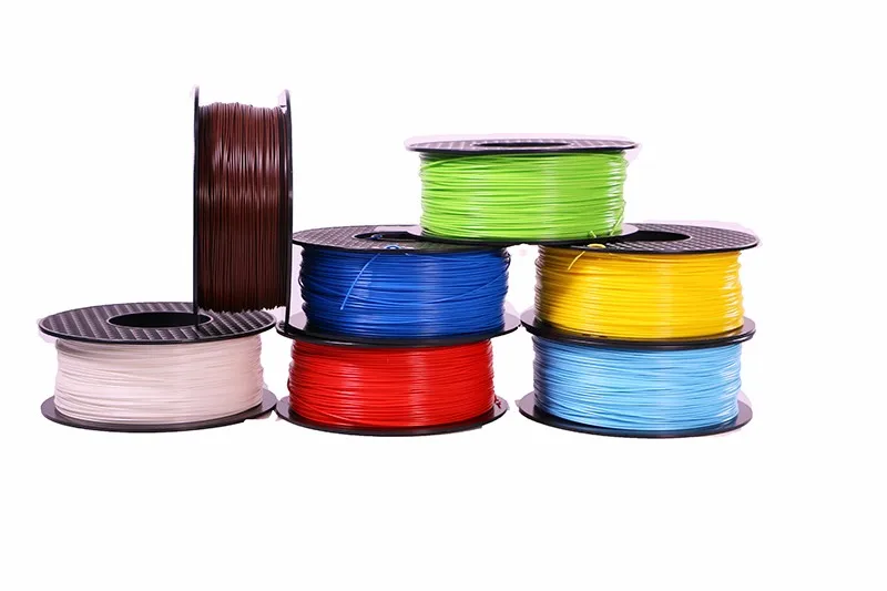 Supports are usually printed:
- HIPS (usually with ABS)
- PVA (usually with PLA)
A glass container like a preservation jar is fine. Any non-porous vessel is suitable for water treatment. To quickly remove props from HIPS/ABS printouts, you will need a solution of equal parts D-limonene and isopropyl alcohol. Many other support structure materials such as PVA (with PLA) dissolve in normal water.
Pro Tricks
Use an ultrasonic cleaner to shorten the solution time and change the solvent as it becomes saturated. A warm (not hot) solution works faster - heating is useful if there is no cleaner.
Pluses
- Complex geometry is allowed for which the standard method of removing props is not possible.
- Smooth surface at the support points.
Cons
- Improper dissolution of the props can cause discoloration and skewed printouts.
- Does not remove layer lines, scratches or other surface imperfections.
- May cause small holes or holes if soluble material seeps into the object during printing.
Cleaning with a skin
SHIP SHIP SHIP ABS ABS ABS PROBECTION
Instrumentation
- E ENDERAL PREASHING WITH
on 150, 220, 400, 1000, 1000 and 2000 - Cleaning cloth
- Toothbrush
- Soap
- Face mask
| Finishing | ★ ★ ★ ★ ☆ |
| Approvals | ★ ★ ★ ☆ ☆ |
| Speed | ★ ★ ☆ ☆ ☆ |
| Suitable for | all thermoplastics FDM |
Process
Once the props have been removed or dissolved, sanding can be done to smooth the part and remove any obvious defects such as blots or prop marks.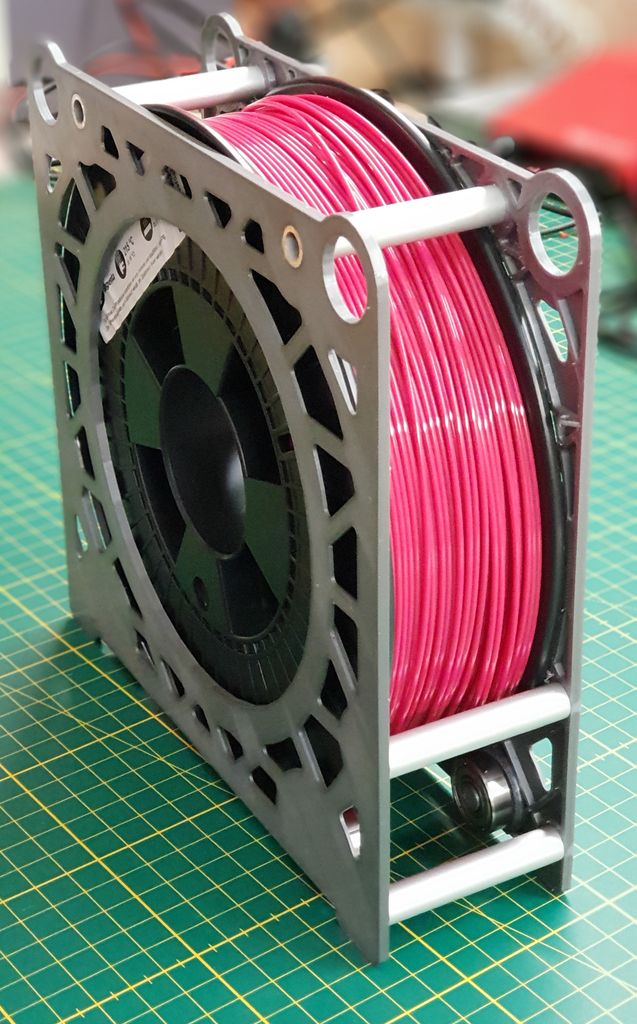 Which sandpaper to start with depends on the thickness of the layer and the quality of the print: for layers of 200 microns or less, or for prints without blotches, you can start with sandpaper at P150. If there are blobs visible to the naked eye, or the object is printed with a layer thickness of 300 microns or more, stripping should begin with P100.
The process can be continued up to P2000 grit (one approach is to go to 220, then 400, 600, 1000 and finally 2000). Wet sanding is recommended from the very beginning to the very end - this will avoid excessive friction, which can lead to an increase in temperature and damage the object, as well as contaminate the sandpaper itself. Between sanding, the printout should be cleaned with a toothbrush and washed with soapy water, then wiped with a cloth to remove dust and prevent it from sticking together. Even P5000 can be sanded to achieve a smooth, shiny FDM part.
Pro Tricks
Always sand in small circular motions - evenly over the entire surface of the part.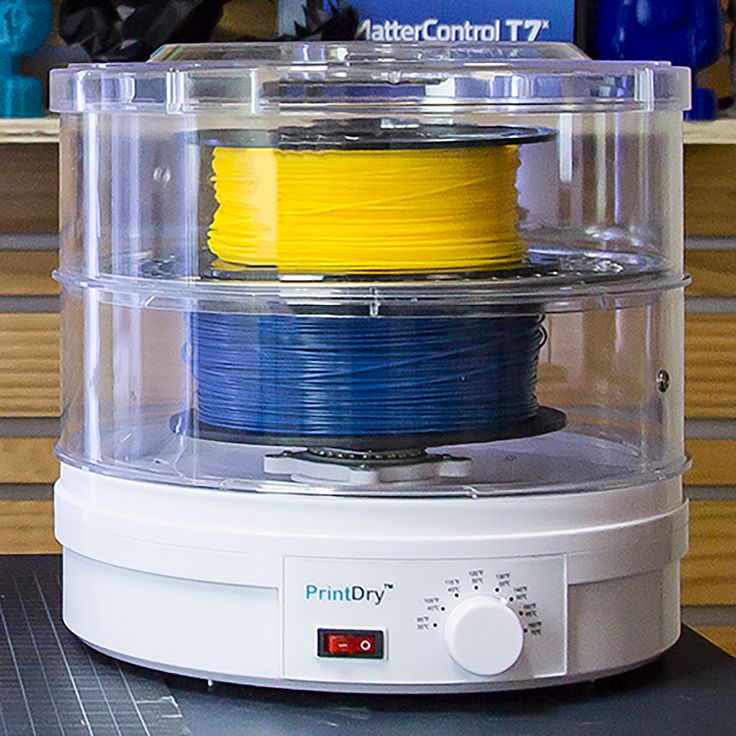 It may be tempting to sand perpendicular to the layers, or even parallel, but this can lead to gouges. If the part is discolored or has a lot of scratches after sanding, it can be heated a little to soften the surface and allow some defects to smooth out.
Pros
- An exceptionally smooth surface is obtained.
- Further post-processing (painting, polishing, smoothing and epoxy coating) is greatly facilitated.
Cons
- Not recommended for double or single shell parts as sanding may damage the printout.
- The process is difficult in the case of sophisticated surfaces and the presence of small details in the object.
- If the grinding is done too aggressively and too much material is removed, the appearance of the part can be affected. Acetone for ABS. Dichloromethane for PLA, ABS
- Foam Applicator
| Finishing | ★ ★ ☆ ☆ ☆ |
| Approvals | ★ ★ ☆ ☆ ☆ |
| Speed | ★ ★ ★ ★ ★ |
| Suitable for | all thermoplastics FDM |
Process
If the size of the object exceeds the capacity of the printer, the object is printed in parts and then assembled. In the case of PLA and some other materials, assembly can be done with Dichloromethane or a suitable adhesive (the choice of adhesive depends on the plastic). In the case of ABS, it is possible to "weld" with acetone. The mating surfaces should be slightly moistened with acetone and squeezed tightly or clamped and held until most of the acetone has evaporated. So the parts will be held together by chemical bonds.
Pro Tricks
Increasing the surface area of the acetone contact increases bond strength. Tongue-and-groove to help.
Pros
- Acetone does not change surface color as much as most adhesives.
- After drying, the compound acquires the properties of ABS, which makes further processing easier and more uniform.
Cons
- Cold "welding" acetone on ABS parts is not as strong as if the part were printed as a whole.
- Excessive use of acetone can dissolve the part and affect final appearance and tolerances.
Void Fill
Black ABS Print, Filled and Sanded
Tool Kit
- Epoxy (for small voids only)
- Automotive body filler (for large voids and joints)
- ABS filament and acetone (only for small voids in ABS printouts)
| Finishing | ★ ★ ☆ ☆ ☆ |
| Approvals | ★ ★ ★ ☆ ☆ |
| Speed | ★ ★ ★ ☆ ☆ |
| Suitable for | all thermoplastics FDM |
Process
Unusual voids may come out after the part has been ground or the soluble props have been dissolved. These voids are formed during printing when the layers are incomplete due to any restrictions on the trajectory of the print head, which is often inevitable. Small gaps and voids can be easily filled with epoxy and no additional treatment is required in this case. Larger gaps or voids left by assembling a multi-part object can be filled with automotive bodywork filler, but the printout will then need to be re-sanded. Putty works great, is easy to process with sandpaper and can be painted. Moreover, the parts connected by such a filler, or voids filled with it, turn out to be stronger than the original plastic.
Slots in ABS printouts can also be filled with ABS thinned with acetone, which reacts chemically with the ABS object and seeps into the existing voids. It is recommended to make such a putty from 1 part ABS and 2 parts acetone, then it will not spoil the surface if used correctly.
Dichloromethane works on all plastics: ABS, PLA, HIPS, SBS, etc.
Epoxy is also useful if you want to make your 3D printed part more durable
Pros
- Epoxy filler is easy to sand and prime, resulting in an excellent surface for painting.
- An ABS solution of the same filament will give the same color so nothing will be visible on the surface.
Cons
- Auto body filler or other polyester epoxy adhesive is opaque when dry and will leave discolored areas on the printout.
- Additional processing required to achieve a uniform surface.
- If the grinding is done too aggressively and too much material is removed, the appearance of the part can be affected.
Polished
PLA model, polished. Photo rigid.ink
Tools
- Plastic Polishing Compound
- Sandpaper for P2000
- Cleaning cloth
- Toothbrush
- Polishing pad or microfiber cloth
| Finishing | ★ ★ ★ ★ ★ |
| Approvals | ★ ★ ★ ☆ ☆ |
| Speed | ★ ★ ☆ ☆ ☆ |
| Suitable for | all thermoplastics FDM |
Process
Once the part has been sanded, a plastic polish can be applied to the part to give a standard ABS or PLA object a mirror finish. After the part has been sanded for 2000, it is necessary to remove dust from the printout with a cloth and rinse the printout under warm water using a toothbrush. When the object is completely dry, buff it on a buffing pad or microfiber cloth, adding a polishing compound as you go, such as polishing jewelry. They are designed specifically for plastics and synthetics and give a long-lasting shine. Other plastic polishes, such as those used to polish car headlights, also work well, but some of them contain chemicals that can damage the printout.
Pro Tricks
To polish small parts, place the polishing wheel on your Dremel (or other rotary tool such as a power drill). For larger and stronger parts, you can use a grinder, just make sure that the part does not stay in one place for too long, otherwise the plastic may melt from friction.
Pros
- The part is polished without solvents that can warp it or change its tolerances.
- When properly ground and polished, a mirror-smooth surface is obtained, very similar to cast.
- Polishing and deburring plastics is extremely economical, making this a very cost-effective method of achieving a quality finish.
Cons
- If you want to achieve a mirror-smooth surface, the part must be carefully ground before polishing, which may affect tolerances.
- After polishing, the primer or paint no longer sticks.
Primer and paint
Gray PLA FDM print spray painted black. 3dhubs.com
Tools
- Cleaning cloth
- Toothbrush
- 150, 220, 400 and 600 grit sandpaper
- Spray Primer for Plastics
- Finish paint
- Polishing sticks
- Polishing paper
- Masking tape (only if multiple colors are expected)
- Nitrile gloves and matching face mask
| Finishing | ★ ★ ★ ★ ★ |
| Approvals | ★ ★ ★ ☆ ☆ |
| Speed | ★ ☆ ☆ ☆ ☆ |
| Suitable for | all thermoplastics FDM |
Process
Once the printout has been properly sanded (it is sufficient to reach P600 when painting), it can be primed. Aerosol plastic primer should be applied in two coats. This primer is intended for subsequent painting of models, provides an even coating and at the same time thin enough not to hide small elements. Thick primer, which is sold in hardware stores, can clump, and then you have to seriously work with sandpaper. Apply the first spray coat with short pressures from a distance of 15-20 cm from the object, trying to do it evenly. Let the primer dry and smooth out the unevenness with 600 grit sandpaper. Apply a second coat of spray with light, quick pressures, also very gently and evenly.
When priming is completed, painting can begin. You can paint with artistic acrylic paints and brushes, but a spray gun will provide a smoother surface. Hardware store spray paints are thick and viscous and difficult to control, so use paints that are designed specifically for modeling. The primed surface must be sanded and polished (sanding and polishing sticks, which are used in nail salons, can be purchased online, they are great for our task), and then wiped with a cloth. The paint should be applied to the model in very thin layers, the first layers should be transparent. When the paint finish becomes opaque (usually 2-4 coats), let the model rest for 30 minutes to allow the paint to dry completely. Carefully polish the paint layer with manicure sticks, repeat the procedure for each of the colors (between each applied paint).
Separate parts of the model can be covered with masking tape so that the colors, if there are several, do not mix. When painting is complete, remove the masking tape and polish the object with polishing paper. Polishing paper, such as 3M or Zona, comes in a variety of grits and is a relatively new product. It is sold in packs in various online stores, and after processing with this paper, the ink layer or topcoat will literally shine - and nothing else can achieve this effect. Apply 1-2 coats of top coat to protect the paint and let it dry completely. The top coat is selected in accordance with the recommendations of the paint manufacturer.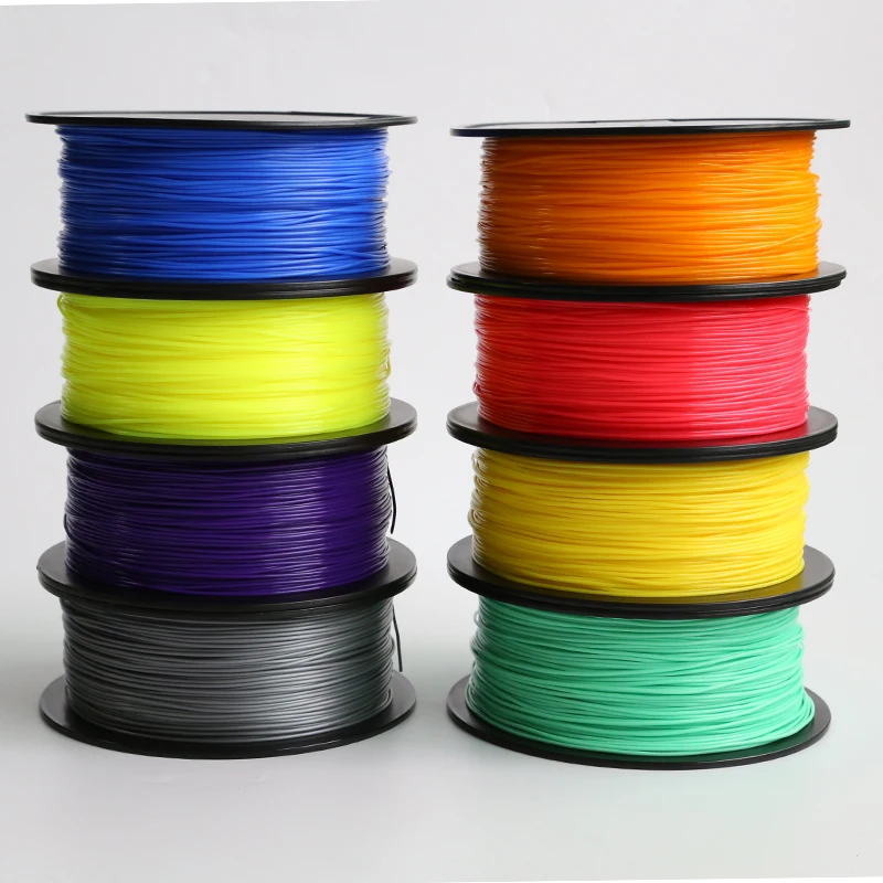 If the topcoat and paint are incompatible, it can render your entire painting job meaningless, so compatibility is very important here.
Pro Tips
Don't shake the can when spraying! It is important not to mix the pigment or primer with the propellant (propellant gas), which will cause bubbles to form in the spray. Instead, the can must be rotated for 2-3 minutes so that the mixing ball rolls like a pearl, and does not strum.
Pros
- Excellent result, if you take into account all the nuances of the process and practice.
- You can do anything with the final look of the object, no matter what material it is printed on.
Cons
- Primer and paint increase the volume of the model, which affects the tolerances and can be a problem when it comes to a part of a larger object.
- High quality spray paint or spray gun increases costs.
Vapor smoothed
Vapor smoothed black ABS printed hemisphere
Tools
- Cleaning cloth
- Solvent resistant sealed container
- Thinner
- Paper towels
- Aluminum foil (or other solvent resistant material)
- Face mask and chemical resistant gloves
| Finishing | ★ ★ ★ ★ ☆ |
| Approvals | ★ ★ ☆ ☆ ☆ |
| Speed | ★ ★ ★ ☆ ☆ |
| Suitable for | all thermoplastics FDM |
Process
Line the bottom of the container with paper towels, if possible along the sides. It is critical that the vapors cannot damage the container and that the container itself is sealed. It is recommended to use a glass or metal container. Apply enough thinner to the paper towels so that they are wet but not soaked - this will also help them adhere better to the walls. Acetone is famous for its ability to smooth out ABS. PLA can be smoothed with a variety of other solvents (dichloromethane works well), but this plastic tends to be much harder to smooth than ABS. When working with any solvents, please follow the safety precautions for handling chemicals and always take appropriate precautions. Place a small "raft" of aluminum foil or other solvent-resistant material in the center of the paper towel-lined container. Place the printout on the "raft" (either side of your choice) and close the lid of the container. Steam polishing can take varying amounts of time, so check your printout periodically. To increase the speed of polishing, the container can be heated, but this must be done carefully so as not to cause an explosion.
When removing the printout from the container, try not to touch it in any way, leave it on the “raft”, take them out together. In all those places where the printout has come into contact with something, there will be defects, since the outer layer will be under-dissolved. Before working with it, let the printout completely “breathe” so that all solvent vapors have evaporated.
Many aerosols and/or solvent sprays are flammable or explosive and their vapors can be harmful to humans. Be extremely careful when heating solvents, always handle them and store them in a well ventilated area.
Pluses
- Many small blotches, as well as many layer lines, are smoothed out without additional processing.
- The print surface becomes extremely smooth.
- The procedure is very fast and can be performed using commonly available materials.
Cons
- Doesn't "heal" gaps, doesn't completely hide layer lines.
- During the smoothing process, the outer layer of the printout dissolves, which greatly affects the tolerances.
- Negatively affects the strength of the printout due to changes in the properties of its material.
Immersion
PLA model immersed in dichloromethane. Photo 3dpt.ru
Tools
- Solvent resistant container
- Thinner
- Eye hook or screw
- Large wire for sculpture or landscaping
- Dryer or drying frame
- Face mask and chemical resistant gloves
| Finishing | ★ ★ ★ ★ ☆ |
| Approvals | ★ ☆ ☆ ☆ ☆ |
| Speed | ★ ★ ★ ★ ☆ |
| Suitable for | all thermoplastics FDM |
Process
Make sure the container you are using is wide and deep enough to completely submerge the printout in the solution.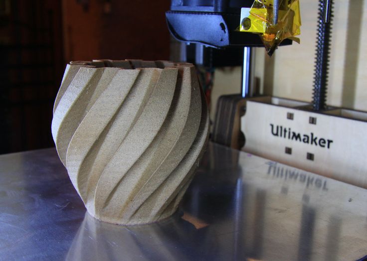 Fill the container with the appropriate amount of solvent - be careful not to splash. As with vapor smoothing, ABS dip smoothing can be done with acetone, which is easy to find in the store, and for PLA, dichloromethane can also work well with ABS, HIPS, SBS, PETG, and many other materials. PLA is quite resistant to solvent smoothing, so it may take several passes to achieve the desired result. Prepare the printout for dipping by screwing a hook or eye screw into it in an inconspicuous place. Pass the wire through the eyelet or wrap the wire around the screw so that the printout can be immersed in the solvent. If the wire is too thin, it will not be able to withstand the buoyancy force on the printout, and it will not be easy to sink the object.
Once the printout is ready, use a wire to completely immerse it in the solvent for a few seconds. Remove the printout and hang it by the wire in a dryer or on a drying frame to allow the solvent to completely evaporate from the surface. After ejection, the printout can be gently shaken to facilitate the drying process and ensure that no solvent has accumulated in the depressions.
Pro Tricks
If an opaque whitish coating appears on the printout after drying, this can be corrected by holding the object over a solvent bath for a while so that its vapor slightly dissolves the surface. This restores the original color of the printout and achieves a shiny outer layer.
Pros
- The printed surface is smoothed much faster than steam polishing.
- Significantly less fumes are generated than other solvent polishing methods, so this method is less hazardous.
Cons
- The surface is smoothed very aggressively, so you can forget about tolerances.
- Immersion for too long can result in complete deformation of the object and a significant change in material properties.
Epoxy
Black ABS printout, half epoxy coated, half uncoated
Toolbox
- two-component epoxy resin02
- Foam Applicator
- Mixing container
- Sandpaper P1000 or finer
| Finishing | ★ ★ ★ ★ ☆ |
| Approvals | ★ ☆ ☆ ☆ ☆ |
| Speed | ★ ★ ★ ★ ☆ |
| Suitable for | all thermoplastics FDM |
Process
After the printout has been cleaned (preliminary cleaning gives the best end result), wipe it thoroughly with a cloth. Mix the resin and hardener in the proportion indicated in the instructions, accurately measuring all volumes. The curing process of epoxy resin is exothermic, so glass containers and containers made of materials with a low melting point should be avoided. It is recommended to use containers that are specifically designed for mixing epoxy resins. Incorrect ratio of resin and hardener can result in longer curing time or no curing at all and result in a permanently sticky substance. Mix the resin and thinner as directed in the instructions - carefully, in smooth movements to minimize the amount of air bubbles remaining inside the mixture. Very little epoxy is needed, and most of these resins only work for 10-15 minutes, so plan accordingly.
Apply the first coat of epoxy with a sponge applicator, being careful not to build up in crevices and small parts. When the printout is sufficiently coated, allow the resin to fully cure - as described in the instructions that came with it. One coat may be sufficient, but for optimum results it is best to lightly sand the printout with fine sandpaper (on P1000 and above) to eliminate any imperfections. Wipe off the dust with a cloth and, in the same way as before, apply a second layer of epoxy.
Pros
- A very thin coat of epoxy won't affect tolerance too much (unless the printout has been sanded excessively hard first).
- A protective shell is formed around the object.
Cons
- The layer lines will remain visible, they will only be covered by a smooth shell.
- If too much epoxy is used, it can flood details and edges, and the surface can appear greasy.
Metallization
FDM printed structural element nickel plated with Repliform RepliKote technology
Tools (for homework)
 If you buy a ready-made solution (as in Midas kits), you can be sure that the problems with plating are not caused by the solution.
  The rectifier is safer in the sense that it can simply be turned off and thus cut off the current during the galvanization process.
 | Finishing | ★ ★ ★ ★ ☆ |
| Approvals | ★ ★ ★ ☆ ☆ |
| Speed | ★ ★ ★ ★ ☆ |
| Suitable for | all thermoplastics FDM |
Process
Electroplating can be carried out at home or in a professional workshop. To do everything right, you need to be well versed in the materials, in what is actually happening - and at home these opportunities are usually limited. In order to achieve excellent surface quality and to have more plating options, including chrome plating, it is best to use the services of professional workshops. The copper galvanization process will be described below as an example.
At home, you can galvanize with copper or nickel, and this coating will then serve as the basis for galvanizing with other metals. It is critically important that the printout surface be as smooth as possible before it is galvanized. Any bumps and lines in the layers will be enhanced as a result of the process. Prepare the sanded and cleaned object for plating by coating the plastic with a thin coat of high quality conductive paint, or with a graphite and acetone solution for ABS printouts. Allow the conductive coating to dry completely, sand if necessary to ensure a smooth surface. At this stage, it is extremely important not to touch the printout with bare hands or to wear gloves, because sweat marks on the object will certainly affect the quality of the galvanization.
Insert a screw or eyelet in an inconspicuous place on the printout and connect it to the negative terminal of the rectifier. This will be the cathode. Connect the copper anode to the positive contact of the rectifier. Fill the container with enough copper plating solution so that the printout is completely covered with it. Immerse the anode in the container and turn on the power. After the rectifier is turned on, immerse the printout in the container, making sure that it does not touch the anode anywhere. Beware! When the object is already in the bath, the galvanization system is active, and contact with the solution, cathode or anode can be traumatic. Set the voltage on the rectifier to 1-3 Volts, and the process will go to full metallization. To speed things up, the voltage can be increased, but not more than 5 volts. When enough metal has deposited on the printout, simply turn off the power and dry the object with microfiber towels. When it's dry, varnish the object to protect it from corrosion.