3D printer axis diagram
CoreXY Kinematics - 3D Distributed
Home
SolidCore CoreXY 3D Printer
CoreXY Kinematics
CoreXY Mechanism DiagramCoreXY Kinematics Explained?
The corexy kinematics mechanical arrangement includes a unique motor movement where the X or Y motor move together or opposite of each other to move the carriage from left to right or towards or away . If you were to move just one motor you would see the print head move diagonal.. If the two motors move opposite of each other the print head will move along the X-axis, If the two motors move in the same direction the carriage will move along the Y-axis.
How Does CoreXY Work?CoreXY-Kinematics-ExplainedThe CoreXY 3d printer design is very different than most common 3d printer motion systems that have dedicated stepper motor for each axis. The core-xy motion system is designed to minimize torque while moving the gantry and carriage.
The corexy parallel kinematics mean’s that the motors are the largest source of inertia within the system, are stationary. This means rapid acceleration because the two stepper motors provide a means of moving both axes independently or simultaneously. The major benefit of the design is that the motors remain in a static position.
The corexy kinematics is a complex motion system where X or Y motor move together or opposite of each other to move the carriage from left to right or towards or away . If you were to move just one motor you would see the print head move diagonal.. If the two motors move opposite of each other the print head will move along the X-axis, If the two motors move in the same direction the carriage will move along the Y-axis.
Two Motors (X and Y)
- Both Motors Move Clockwise >> Carriage Moves Left
- Both Motors Move Counter Clockwise>> Carriage Moves Right
- Both Motors Move Opposite of Each Other>> Carriage Moves Toward & Away
- One Motor Moves>> Carriage Moves Diagonal
see more CoreXY Mechanism Research
CoreXY Motor Movement
| Motor Movement | Direction |
|---|---|
| Both Motors Move Clockwise | Carriage Moves Left |
| Both Motors Move Counter Clockwise | Carriage Moves Right |
| Both Motors Move Opposite of Each Other | Carriage Moves Toward & Away |
| One Motor Moves | Carriage Moves Diagonal |
Is CoreXY Better?
Over the last few years the popularity of the CoreXY kinematics has became a community favorite. New designs, developments and opens source contrubutions have led many to claim it’s the best motion system for 3d printing but that really depends on the user and application.
- Higher Print Speeds: The stationary X and Y motors reduce mechanical weight and momentum giving the motion system a mechanical advantage compared to other motor placement configurations.
- Quality: With the reduced weight and momentum the setup also results in reduced vibrations and increased repeatability at higher speeds.
- Mechanicaly Optimized: With the x and y motors out of the way the machine size compared to actual build volume ratio gives you more printing space with a smaller footprint. Unlike the hbot the corexy carriage isn’t problematic to twisting or buckling when x and y motors rotate in the same direction.
- Maintenance: The longer x and y belts introduce belt tensioning issues(belt stretch).
 The increased number of belt idlers increase maintance.
 - Scalabilty: The belt stretch and tensioning issues introduces a design constraint as the machine size increases.
CoreXY Advantages
The Advantages of the corexy system is the increased print speeds that can be achieved due to the light weight carriage. While 3d printing is a very slow process any kind of reduction in print time is much needed. In addition to faster print speeds the smooth motion that the core xy uses is also known to reduce artifacts commonly found in 3d printed objects.
see RepRap CoreXY
CoreXY vs Cartesian
Most printers utilize Cartesian or plotter style motion where one or two motors will move the carriage from left to right or towards and away. This is the simplest approach in 3d printer motion. While the core xy setup is more complicated but a more efficient approach. The difference between corexy and the cartesian motion system is the corexy reduces inertia from the static motor positions while the cartesian setup uses at least one motor to drive along each axis. The weight of the motor increases inertia making it more difficult to change direction. Which results in the corexy theoretically being faster in and more accurate than the cartesian.
CoreXY Belt Path & Routing
CoreXY Belt Path – Source: Mark RehorstThe corexy 3d printer belt path has been explored in many mechanical arrangements. The main two corexy belt routing methods are belts crossed or not crossed. The main focus should be to keep the belt routing path parallel to the X and Y guide rails. There’s an excellent blog about core xy belt path by Mark Rehorst.
CoreXY vs Hbot
| Type | Pros | Cons |
|---|---|---|
| CoreXY | design balances the forces | more complex beltpath with two crossing belts |
| Hbot | simple design with only one belt | higher orthogonal load known as racking |
A similar mechanical arrangement of the core-xy is the H-bot.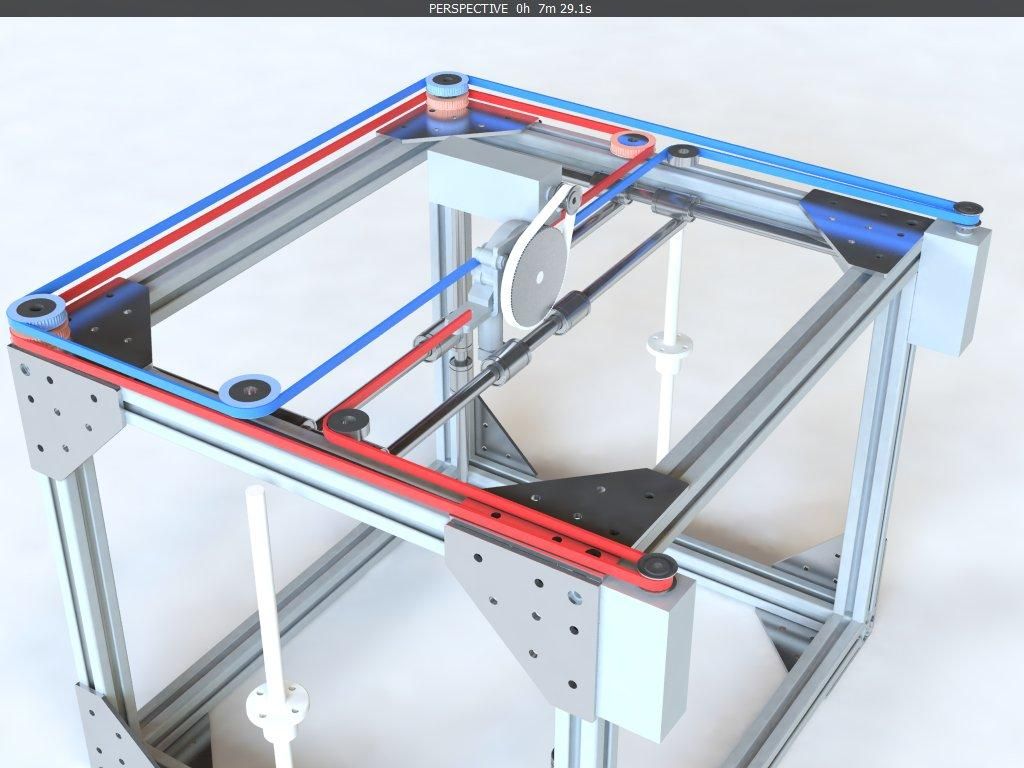 The Hbot uses the same concept of carriage motion as the corexy but is much more simple and requires less math. In addition the hbot is harder to “get wrong.” The corexy belt path has it’s pros and cons. The corexy’s disadvantage is that it requires two belts on two separate planes. The coreXY balances the forces while moving the gantry or carriage to minimize “racking’ where the mechanical system is pulled out of square.
What You Need to Know Before Buying a 3D Printer
Every user is different and has different needs. There isn’t one printer for everybody. You have to consider:
Experience: What is your experince with 3d printers or mechanical components and electroncs that may require technical maintance or steep learning curves.
Application: What kind of parts are you going to print? What size? What materials? How many?
Expectations: What kind of quality or user experience do you expect? What kind of maintance can apply?
Budget: How much can you spend or how much are you willing to spend? You get what you pay for but you may not need much.
Related Content
SolidCore DIY 3D Printer
SolidCore CoreXY BOM
SolidCore Documentation
SolidCore CoreXY Frame
SolidCore Thingiverse 3D Printer Build Plans
SolidCore Kinematic Bed Mounting System Setup
CoreXY 3D Printer Kits
3D Printer Parts
Related Content
CoreXY Belt Routing
There are a few different types of 3d printer kinematics to choose from, with cartesian kinematics being the most common. Recently the corexy architecture has become more popular. In this guide, we will compare corexy vs cartesian kinematics in terms of their speed and print quality so that you can understand the difference in each
by Shane Hooper
The CoreXY motion system is a good solution if you’re looking to print faster.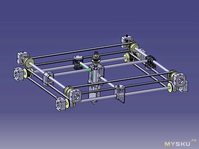 The 3d printer kinematics has become more popular in the last couple of years as users and DIY builders agree on an increase in print quality. The motion system is more lightweight compared to other 3d printer kinematics such as cartesian
by Shane Hooper
CoreXY Belt Routing One of the most important parts for corexy movement is belt routing. Here’s a guide to the mechanics of corexy belt routing pulley layout in order to get accuracy and constant belt tension. Belt Routing Methods There are two main ways to implement the corexy belt path. Either a stacked pulley arrangement
by Shane Hooper
CoreXY Kinematics Explained? The corexy kinematics mechanical arrangement includes a unique motor movement where the X or Y motor move together or opposite of each other to move the carriage from left to right or towards or away . If you were to move just one motor you would see the print head move diagonal..
by Shane Hooper
CoreXY Scalability The scalability of a core-xy printer can be an issue when it comes to hardware design and implementation. An increased belt path can also introduce problems resulting in artifacts in 3d printed parts. A rigid gantry setup is needed and proper binding is a must. 9mm and 12mm belts are available to account
by Shane Hooper
Loose belts are a common problem for users and cause a variety of issues. It may or may not be obvious that your 3d printer is experiencing issues. Belt tensioning defects can occur.
by Shane Hooper
SolidCore CoreXY Z-Axis Bed Leveling We recently started working on the SolidCore 3d printer‘s bed leveling and mounting system. The z-axis uses a 3-point kinematic bed mounting with magnetic pivot spheres on each mount This properly constrains the bed at 3 points of contact. The original SolidCore Z-axis design was somewhat primitive because we only
by Shane Hooper
The CoreXY motion system is a good solution if you’re looking to print faster.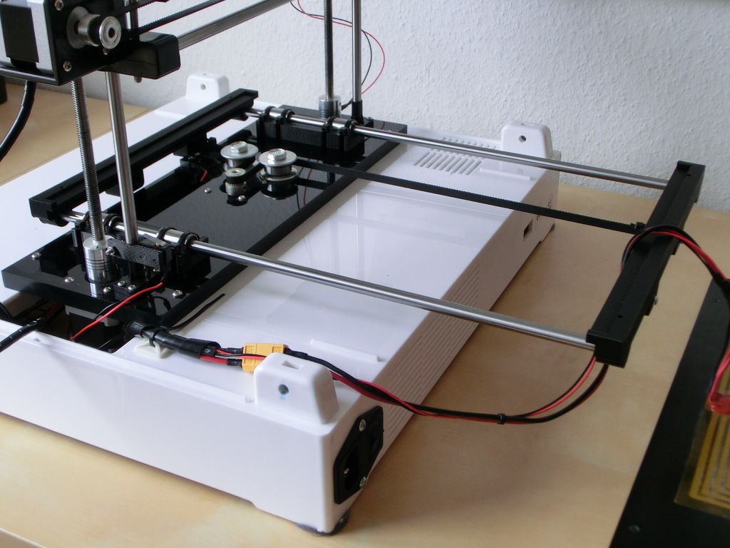 The 3d printer kinematics has become more popular in the last couple of years as users and DIY builders agree on an increase in print quality. The motion system is more lightweight compared to other 3d printer kinematics such as cartesian
by Shane Hooper
The latest design update uses three Z-axis stepper motors. In this arrangement the belt routing to the stepper motor drive the lead screw. Each lead screw will be constrained by an MGN12 linear rail. This should also minimize vibrations that might be transferred from the motors to the z-axis. The belt to pulley ratio gives
by Shane Hooper
Modular
Scalable
Linear Rails
Balanced Carriage Pull
Enclosure
BOM utilizes most available parts
All Metal Parts or 3D Printed
Z-Axis: Independent Driven or Shared Belt Routing
by Shane Hooper
While this write up is still a work in progress as I continue to research kinematic mounting and the math used to find the angle that properly constrains the bed to allow for thermal expansion. This is the documented details of how the SolidCore kinematic mounting system should work. So comment or correct me if
by Shane Hooper
Frame Profile Specs Size 2020 or 20mm x 20mm Style T-Slot Frame BOM Part List Part Quantity Description Source Documentation Folder Frame Extrusions 2020 T-Slot ZylTech Frame Size List Frame Folder 570mm Long 6 Vertical (Tall) ZylTech Frame Size List Frame Folder 430mm Long 3 Vertical (Z-Axis Rail) ZylTech Frame Size List Frame Folder 660mm
by Shane Hooper
Although this page will be used to document and collect resources to implement a toolchanger on the SolidCore printer, we’ve only completed one so far for this case study. The following design analysis is discussing a toolchanger project we prototyped for our customer, Nandan. The majority of the topic currently being discussed is of the
by Shane Hooper
Like this:
Like Loading...
Anatomy of a 3D Printer: How Does a 3D Printer Work?
Get an understanding of how 3D printing works, from the inside and out. This guide will walk you through each of the critical components of a 3D Printer, answering the question: "How does a 3D printer work?"
Posted on February 24, 2016
by
Tyler Anderson
Between the names of the parts and their functions, it can be hard to keep it all straight. Here is a quick guide of the anatomy of a 3D printer. We will focus on mechanical and electrical components of the most common desktop 3D printer type: fused filament fabrication (FFF) or fused deposition modeling (FDM).
Mechanical Components:Print Bed
The print bed is the surface that your objects are printed on to. Typically it will consist of a sheet of glass, a heating element, and some kind of surface on top to help the plastic stick.
Heated/Non-HeatedMost print beds are heated in order to prevent the object from warping while it is being printed. Due to thermal contraction, the plastic will shrink slightly as it cools. This causes the object to warp upwards around the edges and peel off the bed. Heated beds keep the bottom of the object warm, in order to prevent this.
See also; Enclosure, Bed Surfaces. Some printers do not have heated beds. This limits them to printing a narrow range of materials including mainly PLA (the material that is least prone to warping) and sometimes PET.
Print Bed
Bed Surfaces
The bed surface helps the plastic stick to the bed during printing but also allows it to be removed easily when printing is done. There are many different kinds of bed surfaces. Most printers will come with some kind of all purpose surface, like BuildTak or PEI film. However, for best results you will want to use different surfaces depending on the material you are printing. Use this guide for print bed recommendations based on the material.
Bed Surface
Bed Leveling
Many printers have some kind of a system for automatically making sure that the bed is level with the nozzle. Some do not, though, and must be calibrated by hand. MatterControl also has the ability to compensate for unlevel print beds with software. For more information, see our expanded article here.
Filament- This is the plastic that's consumed by the printer. It comes on a spool. Printers use two different sizes of filament, 1.75 mm and 3 mm. There are a variety of different materials. To learn more about them, check out the MatterHackers filament guide.
Filament
Extruder
- The extruder is the core of the printer. It is where the plastic gets drawn in, melted, and pushed out. It is essentially a fancy hot glue gun. It is small, but it is where most of the printer’s technology is located. The extruder consists of two parts; the hot end and the cold end. The cold end has a motor that draws the filament in and pushes it through. The hot end is where the filament gets melted and squirted out.
Direct Drive vs Bowden Extruders Hobbed Gear
Hobbed Gear
Idler Gear
Idler
Hot end - All Metal vs PEEK/PTFEHot end - Heat Sink / Hot End Fan
- This ensures that heat does not travel up the plastic and melt it prematurely before it reaches the nozzle.
 This phenomenon is called heat creep and it causes jams, especially with PLA. This fan should be running whenever the hot end is warm.
Heat Sink
Heater Cartridge
- The heater cartridge is pretty self explanatory. It heats the plastic. It is simply a high power resistor. Almost all modern printers use cartridge heaters, but many older printers used coils of nichrome wire (like the kind in a toaster). If you are replacing your heater cartidge, of even your entire hotend, make sure you know if your system is running 12v or 24v.
Heater
Thermistor/Thermocouple/RTD
- These are all various types of sensors for determining the temperature of the hot end. They are essentially electronic thermometers. Thermistors are the most common type of sensor, but some printers will use thermocouples for extremely high temperature printing.
Thermistor
Nozzle
- The nozzle is simply a piece with a small hole for the melted filament to come out of. Nozzles are interchangeable, and come in various sizes; 0.4 mm is normal, while you might use a smaller nozzle for finer detail or a larger nozzle to print faster. Nozzles can also sometimes get clogged. This is one of the most common issues with 3D printers. See this article for advice on unclogging your nozzle.
Nozzle
Layer Cooling Fan
- This fan cools off the plastic immediately after it is deposited by the nozzle. It helps the object hold its shape. The slicer will turn this fan on and off under different circumstances, depending on what material you are printing. It is not to be confused with the heat sink fan, which cools the hot end itself and not the printed object.
Layer Cooling Fan
Motion Control - X, Y, Z Axis: Delta VS Cartesian
- Cartesian printers move one or two motors along each of the X, Y, and Z axes and the name was derived from the Cartesian coordinates system.
 They typically have a rectangular build area and the printers themselves tend to have a cube-like shape. The Lulzbot Mini is a fine example of these types of printers.
 - Delta printers have three arms that come together in the center to suspend the extruder above the build area. Deltas also use a Cartesian coordinates system to move around in, but instead of moving one motor per axis at a time, all three arms move at different rates or times to precisely move the nozzle with triangulation. The SeeMeCNC Rostock MAX V2 is a prime example of a delta printer.
End Stops (one for each axis)
The end stops are how the printer knows where it is. They are little switches that get pushed whenever an axis moves to the end. This is how the printer finds it’s starting point before printing. Most printers use mechanical switches, but some are known to use optical sensors.
Threaded Rods / LeadscrewsLead Screw
Belt
Stepper Motors
Stepper Motor
Frame
- The frame holds everything together.
 Early printers had frames made out of lasercut plywood. Printers now have frames made of sheet metal, aluminium beams, or plastic. Many parts of the frame are often 3D printed themselves. The more rigid the frame, the more precise the printer’s movement will be.
- Enclosures for 3D printing are used for safety. There are moving parts and heating elements that users will want to protect themselves from. If you printer does not offer an enclosure it is easy to construct your own. Something as simple as a cardboard box could suffice.
-
This takes the 120V AC electricity from the wall and converts it to low voltage DC power for your printer to use
-
ATX Power Supplies- These are the same power supplies used in desktop computers. They have been repurposed for use in many printers. They are very beefy and efficient, and have separate lines that provide power at a variety of voltage (12V, 5V, 3.
 3V).
3V). -
Voltage - some machines run 12 volt systems, while others run 24 volt systems. This becomes critical if you are going to replace components - especially your heater cartridge or hotend. Make sure you order the appropriate parts.
- The motherboard is the brain of the printer. It takes the commands given to it by your computer (in the form of G-Code) and orchestrates their execution. The motherboard contains a microcontroller (essentially a tiny, self contained computer) and all the circuitry needed for running the motors, reading the sensors, and talking to your computer. Here is a comparison of the different motherboards we carry.
- We also have an in-depth article and video on controller boards here.
Motherboard
SD Card Slot
Some printers also have an SD card slot from which they can load G-Code files.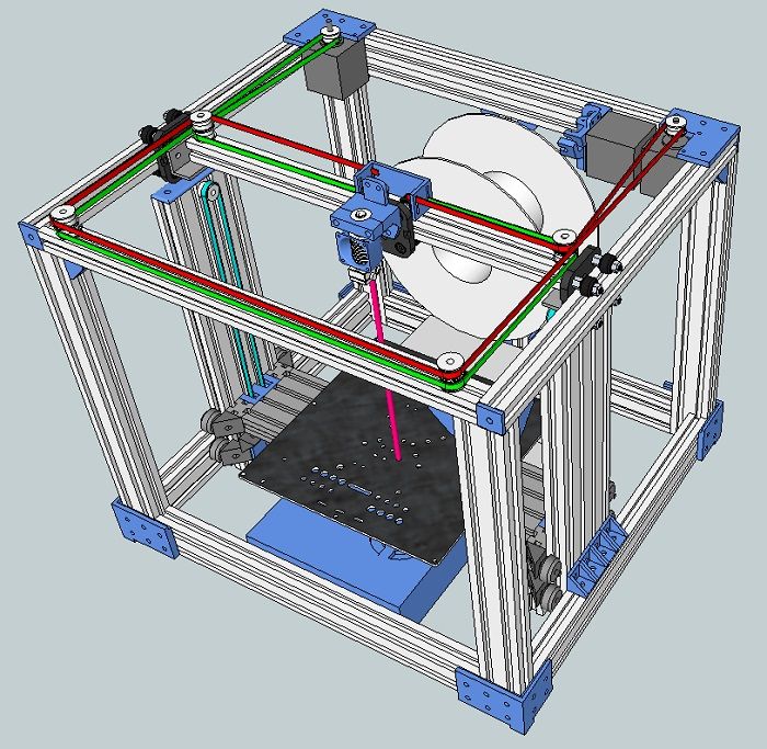 This allows them to run independently without a computer.
- These chips are responsible for running the stepper motors. They fire the coils of the motor in sequence, causing it to move in increments. Many motherboards have the stepper drivers built in, but some also have them in modules that can be unplugged. By balancing the power fed to each coil, the driver is also able to divide steps up into further increments. This is called microstepping, and allows more precise control over the motor than is normally possible. The stepper driver also controls how much electrical current is fed to the motor. More power makes the motor stronger, but also makes it run hotter. See this article for more information on adjusting your motor current.
A set of stepper motor drivers
Screens and User Interfaces- Some printers have an LCD screen so they can be controlled directly without hooking them up to a computer.
 These can be basic black and white displays like the VIKI 2 or advanced enabled touchscreens like the one included on the new Ultimaker S5 3D printer.
Article Tags
- 3D Printing
- Firmware
- 3D Design
- MatterControl
- Press Releases
- Small Business
- Automotive
- E3D
- Jewelry Making
- Engineering
- Entertainment Industry
- MatterControl Touch
- ESD Materials
- NylonX
- BCN3D
- Open Source
- Crafty Pen
- Digital Fabrication Anatomy
- How To
- Hardware and Upgrades
- Tips and Tricks
- Weekend Builds
- Top Ten
- Education
- Tech Breakdown
- Women in 3D Printing
- Project Ideas
- Advanced Materials
- Reference
- Pulse Dual Extrusion
- Product Spotlight
- Aerospace
- Jobs
- Military & Government
- Multi-Tool Machines
- Getting Started
- Healthcare
- How To Succeed With Any 3D Printing Material
- Creality3D
- Architecture
- 3D Printer Reviews
- Hacker of the Month
Related Products
View all related productsWe go down - we grow up, or the Z axis for cheap / Sudo Null IT News
Good day to you, dear geeks and sympathizers! This publication is a continuation of the description of the design of my homemade 3D printer. The Z axis is one of the most controversial printer nodes. What to choose - the ultimate accuracy or good scaling? Move the x-axis or the printer's desktop? Two approaches, two solutions.
I couldn’t look at the first 3D printers without shuddering: the designs were immature, many components were used in violation of specifications, because of the general fluctuation, constant adjustments, minor repairs were required, the size of the working field was small. I decide to solve the problem of internal contradictions by simply crossing hedgehog with a snake portal milling machine and 3D printer designs.
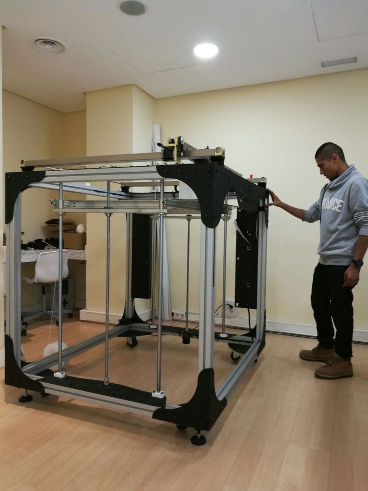
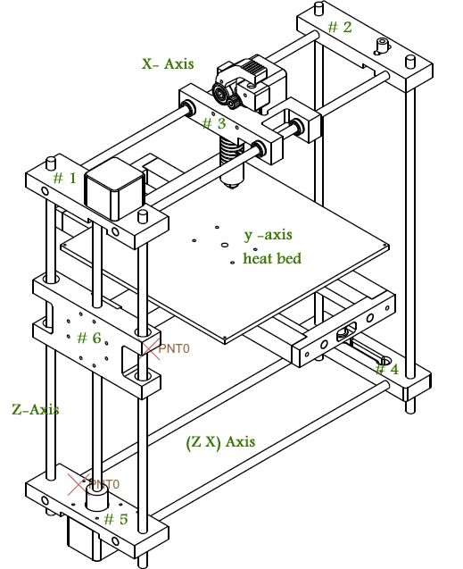
The skeleton of a 3D monster was designed and twisted together:
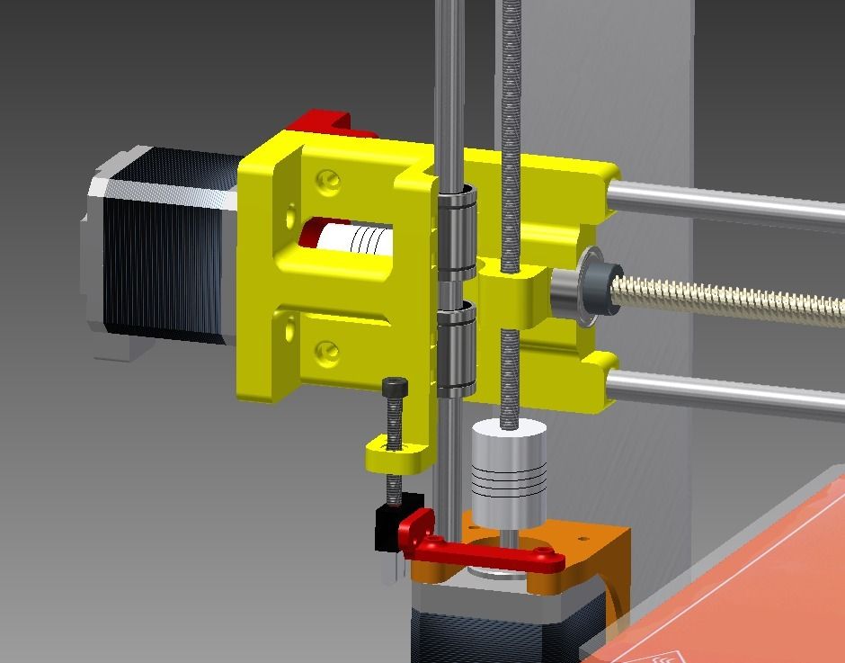
It consists of forty-millimeter aluminum structural profiles connected by thick 45x45 corners and M8 bolts. This design has dimensions of 60x40x40 cm and is absolutely unshakable during normal operation of the printer. The size of the working platform was 45x22 cm, with a maximum height of 28 cm. The carriages are driven by precision trapezoidal screws mounted on angular contact bearings. Each screw is driven by a stepper motor via a 3:1 belt drive. The upper ends of the screws are turned and inserted into needle bushings so that the axial displacement of the screw in the bushing prevents it from wedging during thermal expansion. I used a polymer nut for the screws: there are no high speeds / loads, and the polymer nut is not so demanding on lubrication and is much easier to install. In this design, the height of the model is provided by raising the X-axis above the table, and the Z-axis is used as a movable support for the X-axis.
Operation video:
This axle worked without any problems until this printer was taken apart for parts.
Disadvantages of this solution:
1. Price. Precision components are expensive.
2. Design complexity
3. Poor scalability.
When I began to build the second printer, experience and stinginess were involved in the creation of the design along with an innate desire to go my own way, not expecting favors from nature.
Accordingly, the new printer had to become not only simpler, faster, more versatile, reliable and maintainable, but also much cheaper.
Instead of a screw drive, the Z-axis of the new printer was chosen, but a cable structure similar to a crane winch. It consists of the actual drive mechanism with a belt reduction gear and two blocks on which the entire mass lies along the Z axis.
Here is a photo of the printer as a whole: paired plain bearings made of sintered bronze.
In the next two videos you can see the design of the winch, there is nothing complicated:
Z-axis skeleton: simple and lightweight design.
Power calculations: The drive drum has a radius of 10 mm. Accordingly, a torque of 0.3 Nm (normal Nema 17 motor) on a 10 mm lever will be 30 N. A belt gearbox with a gear ratio of 2: 1 doubles this number.
As a result, the maximum force that this winch can develop is about 60 Newtons, respectively, the maximum mass of the Z axis, together with the masses of the table and the object, should not exceed 6 kg at rest.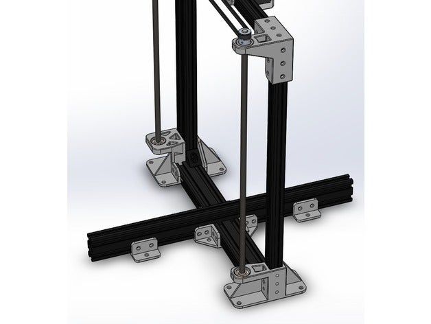
Now let's determine the losses for acceleration and deceleration of the Z axis: to accelerate 1kg of mass with an acceleration of 1m/s², it is necessary to apply a force of 1 Newton. In fact, an acceleration of 1 m / s² for the Z axis is quite enough, and each accelerated kilogram will cost us 1 N of applied force.
The heaviest element in the design is the heated table, it is a duralumin plate 350x350x3 mm, weighing 980 grams with glued heating elements with a total weight of 150 grams.
The rest of the structure, including Basotect thermal insulation, weighs approx.00 grams.
The total weight of the structure is about 2030 grams, which, when rounded up, will require 21 N for holding and another 2.1 N for acceleration. In total, once again rounding up, 24 N.
If we add a kilogram model to the mass of the Z axis, then 34 N will be needed, which is
slightly more than half of the rated winch power. It would seem that the design is redundant in terms of power. But the devil, as always, is in the details. The fact is that in order to achieve maximum torque, maximum currents must flow through the motor windings, which will inevitably cause it to overheat and prematurely fail.
For this reason, I designed the structure with a large power margin, and experimentally set the motor current a little more than the minimum required. At the same time, the motor heated up to 50-60 ° C, which is quite acceptable according to specifications.
In this video, the winch easily juggles the Z axis without a working table, but with two filament spools weighing 1300 grams:
So, the power issue is resolved. Now let's talk about accuracy. Given the parameters of the winch and motor components, with 1/16 microstepping, it is possible to move the Z axis in 0.02 mm increments. Now consider the problem of accuracy in a winch with a single-layer winding of the cable. The radius of the drive drum in my design is 10 mm, respectively, the circumference when winding will be 62.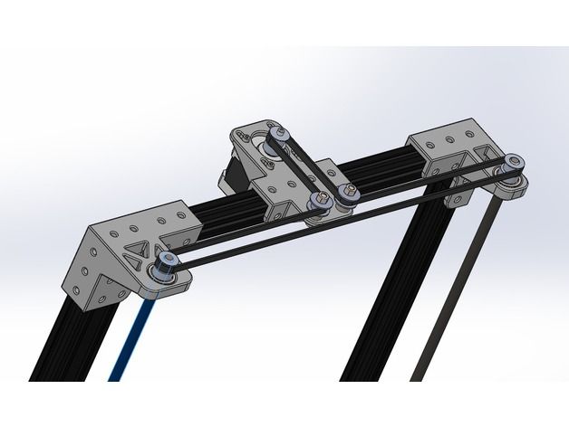 8 mm. It takes about seven turns to raise the Z-axis by 44 cm. When using a cable with a thickness of 1 mm, the axial displacement of the winding will be 7 mm. In this case, there is a change in the distance from the point of contact of the cable with the drum to the lower support block.
Let's calculate how bad everything is: the drive drum is in the center of one of the diagonals of the square formed by the bottom of the printer body. Accordingly, the drum is removed from each of the lower support blocks by 320 mm. By simple calculations, it turns out that when the table is moved by 440 mm, the drive geometry will change by 0.077 mm.
Quality trapezoidal threaded screws provide 0.07 to 0.4 mm accuracy at these distances. Simply put, they do not provide any meaningful gain in accuracy. If for some reason you need to print models with a height greater than 44 cm, you just need to proportionally increase the diameter of the drive drum (to keep the number of revolutions required to move the axis) and the gear ratio (to maintain the nominal load on the motor). At the same time, the cost of the mechanism increases slightly, in contrast to the design with a screw drive.
One of the test objects:
In conclusion, I can say that although experience is a derivative of the difficulties overcome and mistakes made, sometimes the process of acquiring it is more enjoyable than the results achieved.
There will be no 3D models because I can't find them on disk.
Published under the WTFPL license.
And traditional: Have fun!
advantages and shortcomings of all options. Articles of the company "3Dplast - a maker of plastic for 3D friend"
If there is one type of kinematics, it won't collapse under any style. So, like bachite, there are different options - let's sort them out.
Glossary
In order not to stray, let's signify the terms that appear in this article.
Extruder with nozzle and column (working surface) collapsing along the X, Y, Z coordinate axes.
Vіs Y – move back and forth.
Vіs Z - uphill-down.
Head - this is the “head”, that is part of the mechanism, in which the nozzle and extruder are located.
Bed - the same “bed”, the same steel, the same working surface.
XZ Head Bed Y kinematics
One of the widest kinematics. The extruder moves to the right-left and uphill-down, and the steel falls back and forth. Also, such a scheme is often called Prusa, after the name of the retailer of one of the first similar printers.
Advantages of this scheme:
2. Manual access to all nodes - in such printers without borders, you can get to any element of the system and then repair it.
3. Affordable price - logical, if the design is too simple.
Parts of such a scheme:
But in the current models of printers, there are different solutions that reduce the effect.
2. The foldability of the sizing is reasonable, so that in order to improve the first minus of the design, to take away the slightest vibrations, it is necessary to calibrate everything even more.
3. Delamination - the design of such printers is designed to lead to ventilation closing, and "pulls" further worsen the effect of heat shrinkage of certain types of materials. Report here.
Kinematic diagram X Y Head Bed Z
Another scheme in popularity and breadth. The extruder moves to the right-to-left, forward-backward, and moves uphill-downward. Often referred to as Cartesian kinematics.
Advantages of this scheme:
2. Good consistency to each other when milking high firmness to the other.
3. Day of affairs of the nation for the shell of a closed building and for the shell of that which did not collapse to the sides, only uphill and down.
4. Possibility of work even great printers and versatility - this design allows you to increase the size of the outbuilding without losing accuracy.
Parts of this scheme:
Kinematics diagram X YZ Head
Delta printers are used for such a scheme, as they are considered as a visually new phenomenon in 3D-friend. Here, on all axes, the fastenings on three points of the extruder collapse, and the fixing style is unbreakable. Also, following this principle, I use 3D printers as robotic manipulators. But it’s also more expensive solution for those who are not rich.
Advantages of this scheme:
2. Small dimensions in width and great height - give the possibility of being high-necked.
3. Visibility of protruding parts can be removed from the closed housing.
4. Low energy consumption.
Shortfalls of such a scheme:
2. High price and impossibility of self-selection – high accuracy of folding is required.
3. Use more expensive accessories and expensive electronics.
Kinematic diagram Head X YZ Bed
The diagram is slightly expanded. In fact, vikoristovuetsya vsyogo in dekіlkoh printer models dekіlkoh virobnikov. The extruder can only move to the left and right, and the steel moves at two flats - back and forth and uphill and down.
Advantages of such a scheme:
1. High clarity to each other
Small parts of this scheme:
1. High price due to folding design.
2. Possibility to close the body to the risk of thermal deformations.