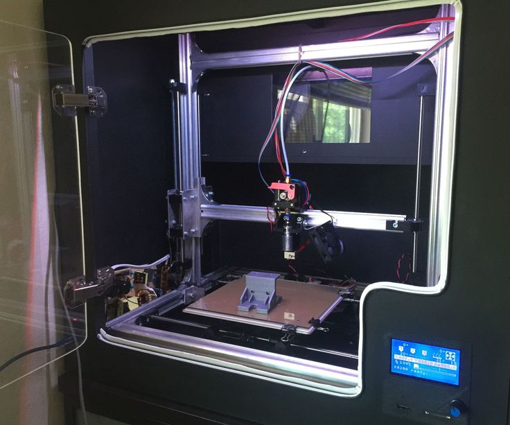
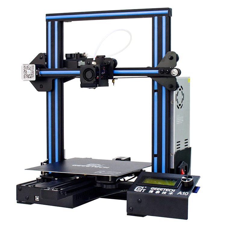
3D print mesh screen
We Should Mass Customize 3D Printed Screens, Meshes, and Filters - 3DPrint.com
As nTopology’s Duann Scott pointed out that they were seeing “a lot of interest in filtering systems.” It’s good to know that this exciting application is getting some traction. 3D printed filters, screens, meshes and filtration systems are part of a hidden application that is occurring but underutilized and under-publicized. A lot of companies are turning to additive to solve complex filtration and flow problems, but the part volume is very low. So, our industry may not really understand yet just how fruitful it will be to create filtration products using additive manufacturing (AM).
HP and AIM Sweden have just about the only well-publicized and well-understood cases of 3D printed meshes. In both their cases fiber mold tooling can be optimized through 3D printed molds that are really a combination of a series of molds and screens. These tools break down less because flow can be optimized by controlled porosity. Holes themselves are more precise and less likely to inhibit flow. This means less breakages occur and productivity is increased.
By making the tools cost effective and longer lasting the advantage of it being quick to produce is further enhanced. This is no highfalutin, super cool idea for the future. This is a tool that can be used now to make egg cartons more cheaply. If there is a new shape, a new trend, or a new development new tools can be made more rapidly. But, even if its bog-standard egg cartons, the HP and AIM tools are made to cost effectively replace the exiting tooling. This is the kind of thing that I love. With considerable understanding of a little-understood market, both of these companies have figured out how to make a 3D printed solution that works now.
I like the reality and cost effectiveness of this. We’re not talking about a heat sink for a satellite or a part of a rocket engine. This is everyday industrial stuff. Also, the customer doesn’t need to delve into design for additive manufacturing, understand AM, train their people to design, or buy a machine.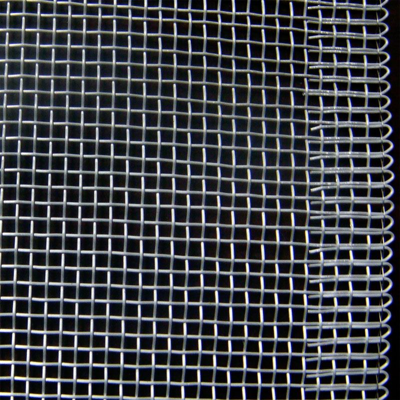 They can just order these tools when they need them. To me these kinds of applications are what we need to grow the market.
Our current position is: invest $2 million and two full-time employees, take a year, and you can learn additive. This is nonsense. There are thousands of very specific, software-enabled services that can design millions of parts through simple mass customization that could be used in industrial processes. Let’s stop focusing on force-feeding industry our whole technology, but rather switch to offering specific tools to easily obtain 3D printed parts. Let them get their toes wet in minutes for thousands of dollars and then maybe they’ll buy a machine. If they don’t, we can keep selling them high-value parts. Rather than get locked into never-ending negotiations on the single-digit margin world of manufacturing, we can continue providing high-value solutions in low volumes over time.
Beyond molded fiber tooling, where else could we find fruitful applications for 3D printing? Here electrospinning and 3D printing are used to make 3D printed filters for masks.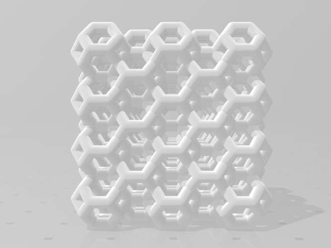 ExOne demonstrated the benefits of control over porosity in binder jetting when it 3D printed copper mask filters last year, a skill that it applies to industrial filters as well. 3D printing membranes have long been an area of interest. Croft used 3D printing to make a wide variety of filters and has made custom filters with 3D printing since 2014. These filters can be custom designed and made, sometimes in less than two days, for pharma, food and beverage, and oil and gas.
A large number of filtration systems have been made with 3D printing. Here, Korean and Indonesian researchers show us how they’ve developed a complex filter for arsenic removal. In this application we learn:
“Our proposed filter has a simple design and can easily be produced at low cost. Simple changes in the architecture of the filter had the following effects: As the channel width became narrower, corresponding to an increase in the internal surface area of the 3D printed filter, (1) more iron (III) oxide (adsorbent) was deposited on the inner surface of the filter, and (2) the flow rate under atmospheric conditions (without external pumping) decreased.
The larger deposition of iron (III) oxide and the decreased flow rate led to better removal of arsenic.”
It’s a great example of how filters can be low-cost, while being high-performance due to the design freedom we have in 3D printing. This is an excellent article giving an overview of 3D printing techniques used for water filtration. Here is another focusing on water treatment, this case demonstrates the use of clay for producing filters using an Ultimaker. In another study, a rather more exotic material, graphene aerogel, was used as a water filter. The paper concluded that, “100% organic solvents over 10 cycles of regeneration and reuse” and that,
“The potential and vision of the 3D printing approach for graphene-based water treatment presented here can be extended to other functional nanomaterials, can enable shape-specific applications of fit-for-purpose adsorbents/reactors and point-of-use filters, and can materialize the large-scale manufacturing of nano-enabled water treatment devices and technologies.
’
A much more commercially ready application is being explored by Singapore’s Nano Sun, which is using PVDF to make 3D printed micro filtration membranes. The company is developing containerized water filtration solutions capable of processing 500 cubic meters of water per day. The company is also doing reverse osmosis water desalination to the tune of 1440 cubic meters a day in Singapore.
As with 3D printed batteries, mass customized 3D printed heatsinks and mass customized 3D printed nozzles, I think that meshes, screens and filters are a perfect business case for mass customization and 3D printing. We can make lighter, more efficient filters specific to many applications that will outperform some existing filtration devices, in a cost effective way. To me, application-specific mass customization tools, startups, and services are the fastest ways to open up and conquer many suitable industrial applications quickly. By not focusing on machine sales but rather on delivering specific geometries for optimal applications we can unlock new markets profitably and quickly.
Stay up-to-date on all the latest news from the 3D printing industry and receive information and offers from third party vendors.
Tagged with: 3d printed clog prevention screen • 3d printed filters • 3D printed magnetic blood filters • 3d printed mesh • 3D printed microwave filters • 3D printed water filter • carbon filter • filtering • mesh
Please enable JavaScript to view the comments powered by Disqus.
The Basics of Screen Mesh Printing
The Basics of Screen Mesh Printing | ASADA MESH CO.,LTD.- HOME
- Product Introduction
- The Basics of Screen Mesh Printing
- Screen Printing
- Technical Information-02
In recent years, individual material technologies in Screen Printing have improved dramatically, which has made it possible to print a line width of 50 micron or less in various fields.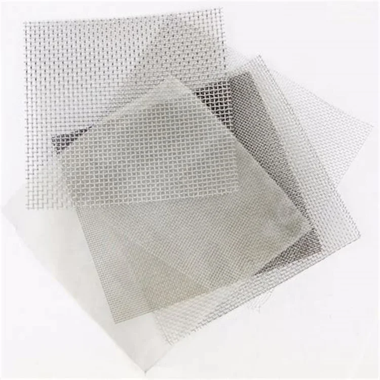 Although Screen Printing is well known for superior usability and versatility in the manufacturing process, high Quality Screen Printing in electronics industries must be used under the strictest conditions with optimized materials and settings.
“A-Type” introduces a number of fundamental pringciples of Screen Printing as well as more advanced technologies to develop Screen Printing further.
Factors that affect Stainless Steel Wire Mesh
Tensile StrengthIt is better to select the mesh with the highest possible Tensile Strength. It helps other parameters like peel-off velocity, dimensional accuracy, screen life, and so on, thus mesh strength is the most important aspect in printing. It is necessary to pay more attention to the mesh strength when printing narrow lines because the tensile strength of a finer mesh with thinner wires is usually lower. For accurate dimensional screen printing, or when printing with high viscosity paste and have tougher peel-off, Ultra-Hard HS-D mesh is highly recommended.
Discharging ink volume fluctuates depending on Screen Mesh opening rate. When the opening rate is too high it often causes bleeding and the printed resolution becomes less clear. We recommend 40% opening rate for fine line printings.
Opening RateThicknessMesh thickness influences the print laydown and the resolution directly. Mesh thickness can be reduced by a process called Calendering.
Mesh CountPrinting performance becomes most stable when the screen opening has more than double the mesh pitch (25.4mm/mesh count). Even when the screen opening has only 1.5 times the mesh pitch, ink with high printing performance makes quality printing possible. Moreover, by optimizing the viscoelasticity of inks, the opening can be reduced down to 0.8 times the mesh pitch.
Mesh pitch x2 Mesh Pitch x1.5 Mesh Pitch x0.8| BS | 325 | 28 | Direct Stretching | 41% | 60 | 55/40 | 1. 0078 0078 | 78 |
|---|---|---|---|---|---|---|---|---|
| MS | 400 | 23 | PS Trampoline | 41% | 55 | 40/26 | 1.0864 | 64 |
| MS | 500 | 19 | PS Trampoline | 39% | 41 | 36/20 | 0.9351 | 51 |
| MS | 640 | 15 | PS Trampoline | 39% | 35 | 21/17 | 0.7340 | 40 |
| HS-D | 360 | 25 | SS Trampoline | 42% | 59 | 41/29 | 2.5671 | 71 |
| HS-D | 500 | 19 | SS Trampoline | 39% | 45 | 25 | 2.0541 | 41 |
| HS-D | 650 | 14 | SS Trampoline | 41% | 34 | 23/17 | 1.4539 | 39 |
Scroll Side
Recommendations for Screen Making
Bias AngleStadard bias angle is 22.5°. The bias angle is determined by the direction of warp wires.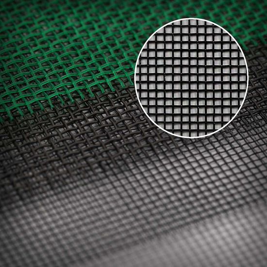 It is reccomended that squeegee direction be set parallel to the warp wires.
There are 2 types of screen stretching – Direct Stretching and Trampoline Stretching. Direct Stretching is when the stainless steel wire mesh is stretched and glued directly onto a frame. Trampoline Stretching uses a stainless steel wire mesh adhered to a polyester mesh; it is recommended when a fine mesh is stretched on a frame.
Screen Tension LevelSelect a frame of high strength and stretch the mesh with uniformed tension.
When the Strength Index is over 1.0: 28±2N/cm
When the Strength Index is around 0.7: 23±2N/cm
※Tension Gauge:Protec STG80NA
Area SizeThe printing image should be smaller than 50% of the inside dimension of the wire mesh size. The trampoline should be 75% of the inside dimension of a frame.
Area SizeEmulsionSelect an emulsion with an excellent resolution and solvent resistance.
When the emulsion thickness is less than 20 microns; it is recommended that a Flattering Treatment be used to improve the smoothness of the emulsion (RZ Value).
“Water-repellent” emulsion can reduce bleeding caused by low viscosity paste.
Recommended Printing Conditions
SqueegeeSelect an 80 durometer hard urethane squeegee with an excellent in solvent and abrasion resistance.※1 Blade Size: 9 x 45-50mm Polish a squeegee edge around 50 micron with a grinder so that it reduces the fluctuation of printed images. “Both sides Grind” Squeegee is useful when an attack angle needs to be set less than 55 degrees.※2
※1. MINO GROUP MINO PLAIN® hardness 80°or equivalent product
※2. MINO GROUP WS cut squeegee® or equivalent product
A Scraper plays and important roll– coating and returning paste and keeping screen wet during printing. When set at the proper setting, it enhances the accuracy of printed images. When the paste viscosity is higher, increase the pushing force and set the Scraper lower.
There are only 4 printing parameters.
Snap-Off Distance
Standard Snap-Off distance is 1/300th the inside dimension of a frame when the mesh strength index is above 1.0. 10,000 shots are normally possible without causing plastic deformation.
| STG75B | STG80A | 320(inside280)mm□ | 550(inside470)mm□ | 1000(inside900)mm□ |
| 0.95mm | 0.23mm | 0.9mm | 1.6mm | 3.0mm |
Scroll Side
As mesh strength index is higher, the allowable range of snap off distance is wider.
Squeegee Pressure
Set pressure comfortably over 0.5kgcm of the squeegee width. Ex)50cm width squeegee: 50cm x 0.5kg = 25 kg
Low squeegee pressure causes a fluctuation in printed images. When the pasete viscosity is higher, set squeegee pressure higher than usual to get a better paste release.
Squeegee Angle
Squeegee angle determines the “fillling force of paste through the mesh. A smaller angle makes the “filling force” bigger. In normal circumstances, 70 degrees is the standard angle. For high viscosity paste, 40 to 60 degrees is best, and 20 to 30 degress is best for via-hole filling.
Squeegee Velocity
Squeegee velocity also influences the “filling force” of paste through the mesh. Low velocity makes “filling force” higher and high velocity makes it smaller. Too much “filling force” causes bleeding and too little causes blurring, Appropriate squeegee speed is determined by paste viscosity and peel off condition.
Printing Quality ConfirmationFirst, check the condition of scraper coated ink on the screen surface, then peel-off performance alongside the squeegee movement, and last, the uniformity of the screen surface after the ink is scraped off. The printed image should be observed with a stereomicroscope or a CCD camera right after printing, before it dries. The surface of the printed wet image reflects the ring illumination light, which makes it easier to observe thickness uniformity. Check the outcome of the second print and if it is good, check the outcome again after 20 continuous printings to make sure that the printed shapes have no distortion.
By using a large quantity of slow-drying solvent, rinse the screen from the squeegee side gently without damaging the other side (emulsion side), and clean out the screen openings. If the cleaning follows the appropriate steps there should be no problem washing even the screens with 30-micron line patterns. Poorly washed screens can cause printing problems like line cutout. Explained below are the basic steps of screen cleaning.
Watch the Video
Preparing to wash the screen
-
Collecting Paste from the Printer
Collect left-over paste from the squeegee side of the screen by scraping with a short squeegee.
-
Deciding on Cleaning Solution and Cloth
Decide on a cleaning solution that can dissolve the paste, slow drying as to not damage the emulsion on the screen, and is water soluble and ethylene-glycol based.The cleaning cloth should be soft and absorbent, and made of something as least likely to leave fiber residue.
Recommended Cleaning Solution: Toho Chemical Industry’s Toho Clean RX-850 -
Application of Cleaning Solution
Lay a cleaning cloth well soaked in solution on the stainless steel pad. Put the emulsion side of the screen down on it, and spread cleaning solution on the squeegee side. Do not wipe off the paste left on the screen, but rather rinse the paste out of the openings or wherever else.
-
Washing the Screen
With the cloth, first clean off the paste stuck to the parts of the screen outside the pattern. Next, very gently, use the cloth to clean the paste stuck to the pattern area from the inside out.
 Each time you use a new cloth make sure to soak it liberally in the cleaning solution, and be careful not to let the paste dry in the openings of the emulsion. For paste that is stuck hard in the emulsion openings, use the cleaning cloth to tap lightly from above to clean it out.
 -
Rinsing off the Cleaning Solution
After thoroughly cleaning the paste from the squeegee side of the screen, use a thoroughly soaked cloth to tap the emulsion side of the screen to clean. Perform this once or twice, and as carefully as possible as to not damage the screen. Last rinse off the cleaning solution from the squeegee side as well. If the screen is big, stand the screen up in a plate cleaning platform and perform the same steps as above.
-
Confirming the Screen is Clean
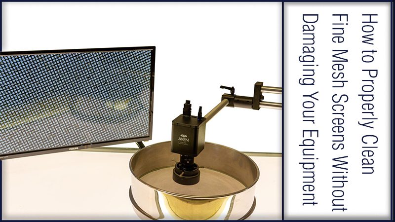
After cleaning, use a microscopic camera or something similar to check if the paste has been cleaned from the emulsion openings.
-
Finishing
Use tap water in a spray gun to thoroughly rinse the cleaning solution from the squeegee side of the screen.
 Next, use an air blow gun to completely remove the water, starting from the edges and working your way to the center.
Recommended Hand Spray Gun: Anest Iwata W-71 Series -
Drying
After air blowing off the water, put the screen in the dryer at 40 degrees Celsius for about one hour. Make sure the screen is completely dry before using it again.
Pastes used in screen printing must have an elastic property. Such pastes have time-sensitive characteristics, namely that viscocity decreases as shearing force is applied.
Also, when measuring the viscocity of the paste (fluidity of the paste), we recommend using an E-Type viscometer which will allow you to measure the shear rate precisely.
The range of paste viscocity you can use for screen printing goes to as high as 400Pa.S (5rpm). For high-definition printing, we recommend using a paste with high viscoelasticity and high shape retaining property.
Requirements for 3D Models for 3D Printing and CNC Machining
01/16/2017 in 3D Modeling Instructions
Contents:
- Introduction
- Product creation process.
- Requirements for models for 3D printing and CNC processing.
- Fixing non-critical bugs with NetFabb.
- Fixing non-critical bugs with MeshMixer.
- Fixed non-critical bugs with Materialize Magic.
- Examples of the most common errors.
Introduction.
In this article, we will talk about the basic and general parameters that a model must meet in order to obtain high-quality 3D printed products. Let's discuss common errors that occur in the process of creating three-dimensional models in terms of a high-quality polygonal mesh and how to quickly fix them. Requirements for 3D models and quality issues in terms of the accuracy of manufactured parts are described in another article: The actual size of the product after 3D printing.
The process of creating a product.
Structure of the additive manufacturing process for the production of products:
| Designer / 3Dartist | 3D printing service | Discussed errors |
| 1. Creating a 3D model | ||
| 2. Export/convert 3D model to required format | 3. Model validation | 4. Compliance / non-compliance with the minimum allowable thicknesses. |
| 6. Preparation of control program for 3D printer (GCode) | 5. Compliance / non-compliance with the requirements for the polygonal mesh of the 3D model. | |
| 7. 3D printing process. | ||
| 9. Quality control. | 8. Post-processing process. |
In accordance with the presented algorithm, at the first stage of product creation, a 3D model is developed using modeling programs in accordance with the terms of reference and the requirements of standards.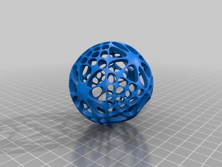 After that, it is necessary to export the data of the simulation result program file to a format accepted by the program of the additive manufacturing control machine (for example, “STL”). The modeling process can now be done not only in solid format, but also immediately in STL. Before the next stage, possible defects in the model are identified. A model intended for 3D printing must be hermetic, monolithic and not contain cavities and gaps in the walls, which is ensured using special programs. Next, the information from the STL file is converted into commands, following which the 3D printer produces a product, this is the so-called GCode.
During this procedure, you should select the desired scale of the part, the correct position in space, and accurately position the model on the work surface. The result of the whole process, strength, surface roughness of the part and material consumption depend on this . After the settings are made, the model is divided into layers of material, which are “fitted” into the body of the part in one working cycle of the additive machine.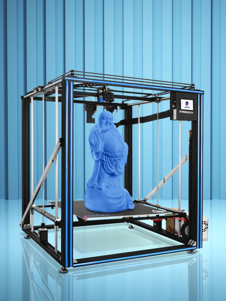 This process is called slicing. Slicing is done using the software supplied with the machine, or using special tools (Simplify, Skein-forge, Slic3r, KISSlicer, MakerWare, etc.). The G-code obtained in the previous step is transferred to the 3D printer via flash memory or via a USB cable. In the process of preparing and setting up the additive machine, calibration, preheating of the working bodies, selection of the model material and setting the parameters of the equipment operation modes that depend on it are performed. On professional level devices, this step can be combined with the slicing process procedures. After all the preparatory operations are completed, the printing process starts, that is, the layer-by-layer combination of materials. Its duration depends on the type of technology and the selected parameters for the accuracy and quality of the part.
Requirements for models for 3D printing and CNC processing.
- List of file formats by 3D technologies.
- FDM (ABS, PLA, FLEX, HIPS, etc.
 ): .STL .OBJ
 - SLS (polyamide): .STL .OBJ
- SLA, DLP (photopolymer): .STL .OBJ
- SLM (metal): .STL+STP(STEP) .OBJ+STP(STEP)
- Multicolour plaster: .OBJ+texture .WRL+texture
- Polygon mesh.
- The mesh must be uniform and closed. A model consisting of several polygonal meshes is not allowed! Intersection of polygonal meshes is not allowed! Holes in the grid are not allowed!
- Multiple models in one file are not allowed. Each object needs to be saved as a separate file.
- The number of polygons must not exceed 500,000.
- Wall thickness must be at least the specified values for each technology.
- Inverted normals are not allowed! The outer normal should face outward. This problem is especially common when mirroring the model in some 3D modeling programs.
- The dimensions of the model must correspond to the dimensions of the real object.
In 95% of cases, errors in files are not critical and can be easily fixed using specialized programs that can be easily found on the Internet. Even if you are sure that everything is in order with the model, it does not hurt to check it once again for correctness.
NETFABB - as a solution to most file errors.
MESHMIXER is a powerful and convenient alternative.
- Wall thickness analysis of the model.
It should be understood that there are several 3D printing technologies. They differ not only in the materials used, but also in the accuracy of the equipment. Different equipment has its own resolution. Therefore, before sending the file for printing, it is necessary to make sure the quality of the model in terms of the specified thicknesses in the walls, rods, mesh ceilings. Detailed article about checking models for thickness.
Fixing non-critical bugs with NetFabb.
NETFABB (download for PC or download for Mac) is a program that allows you to solve almost any issue related to 3D printing.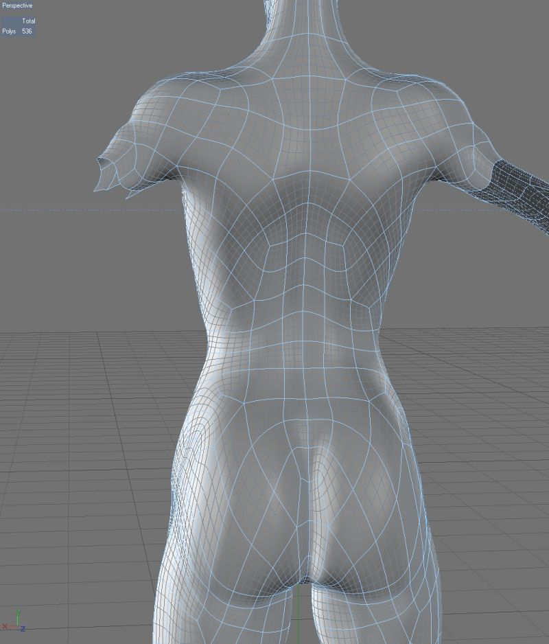 Let's go through the main functions of this software, which AutoDesk itself bought at one time.
The program shows the outer part of the polygon in green, its inner normal in red. Ideally, the model should be all green. If you observe red spots, then these are polygons that are turned outward. If the entire model is highlighted in red, then the entire mesh is turned inside out.
Even if the model is green, but there are errors in your file, the program will display a big exclamation mark in the lower right corner of the screen, and will also not be able to calculate the volume of your model.
To treat the model, click on the red cross on the toolbar at the top of the screen. The program will put you into the treatment mode, and will indicate in yellow the breaks in the polygonal mesh, if any.
This program has functions for removing or adding polygons, changing sizes or proportions. (I will leave these functions for independent study).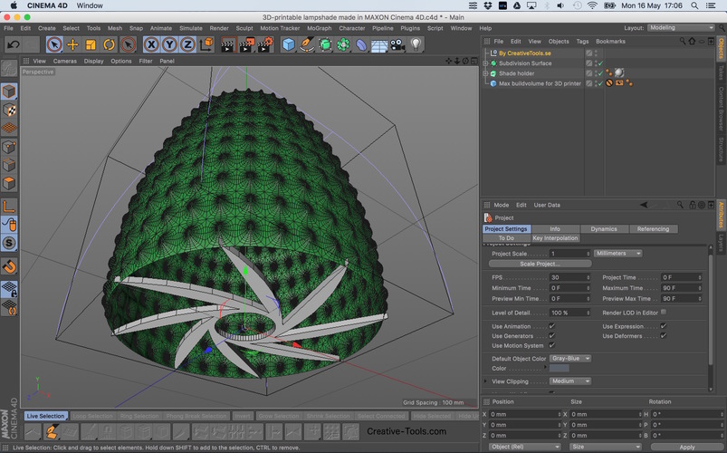 I recommend that you study the entire toolbar in order to easily understand how, where and which polygons we can select and what we can change.
To invert normals, select the polygons that look “in the wrong direction” and click on the “invert normals” button. Then click on the “Apply Repair” button.
If your model was initially all green or inverting the normals didn't remove the exclamation mark, and the volume has not yet been calculated, you need to apply automatic treatment. To do this, go back to the treatment mode by clicking on the red plus. In the treatment mode, select "Automatic treatment", then select "Default Repair" and click "Extrude".
The program has now done its best to repair the model automatically. Click "Apply Repair".
Typically, these steps should have fixed your model. If after the performed operations an exclamation mark is on and there is still no volume, then you are among those 5% when the model has critical errors and errors are laid down at the modeling stage.
Fixing non-critical bugs with MeshMixer.
Autodesk MeshMixer is a free program for working with 3D mesh models. You can download the program from the link. The program does not have tools for creating 3D models, but a wide range of tools for modifying them and preparing them for 3D printing. The main difference between this software and NETFABB is that MESHMIXER officially supports the latest versions of macOS. For me, this is a decisive factor, because I always carry a MacBook with me, and a Windows computer is only in the office. In turn, NetFabb stopped supporting software for macOS.
As in the case of Netfabb, you need to drop the model in STL format into the MeshMixer program window.
At first glance, the model looks good, but let's try to test it for suitability for 3D printing (mesh requirements). To do this, you need to analyze the model for errors. To do this, go to the “Analisis” section, then click on the “Inspector” button.
On the screen, we see how the program has highlighted areas on the model with bright colors that do not meet the requirements, which means they have errors.
In order to fix (cure) these errors, click on the “Auto Repair All” button. The program will try to remove errors automatically. Checking before 3D printing is a must. Even if outwardly the model seems suitable to you, it is still worth checking. In the picture below, you can see the errors that are inside the mesh, although everything looks good with the model.
However, this treatment does not always help. For example, if the model has a huge number of errors that the program is not able to remove automatically, then you will have to correct the model yourself in the program where the model was originally created. In case of a large number of errors, the program will indicate their presence even after you have tried to do automatic treatment. The picture below is an example of a very large number of shortcomings and errors that the program is not able to remove by itself.
This usually happens when the model is being prepared for rendering rather than 3D printing. That is, there is a huge number of surfaces, but they are not connected into a single grid.
Fixing non-critical errors with Materialize Magic
The 3D model healing feature in Materialize Magic is located in the Fix tab.
After that, select the “Correction Wizard” command. Next, you need to alternate the “Update” and “Autocorrect” buttons.
Do this several times. Sometimes for a long time. Until the moment when the number of errors becomes minimal or disappears altogether.
After the upgrade, the result shown below can be considered successful. All checkboxes must be green.
Complete the treatment by following the recommendations and save the corrected model!
A very important point! Treatment in automatic mode occurs according to the principle of adding or removing polygons. Therefore, after automatic treatment, fully check the model for the correct form. Suddenly, the program removed something or added something superfluous.
Finally, the final model must be checked for wall thickness. All programs described in this article support this feature.
Let the video card help you in learning 3D modeling programs. =)
Examples of the most common mistakes.
Too thin walls in the 3D model on extruded parts.
Multiple sections less than 1 mm thick
Reversed polygons, infinitely thin walls
Error converting to STL format, low polygonality
Inverted polygons, infinitely thin walls
Inverted polygons, polygons overlapping each other
Extra garbage from polygons
Poor quality 3D scanning without result processing
Tags: 3D printing, 3D printer, 3D printers, 3D scanning, netfabb, Additive technologies, Parts, Inventions, Equipment
Irregularity in 3D printing allowed the creation of a plastic analogue of fabric
materials 3D printing
Complexity 2.4
Jack Forman et al. / UIST 2020
American engineers have learned how to print mesh structures on a 3D printer, which are similar in structure and properties to fabric. They are obtained when the material exits the printer extruder unevenly. The method allows you to create a "fabric" structured on different scales, designed for different applications, say the authors of an article presented at the UIST 2020 conference. on the other hand, it can be stretched, bent or wrinkled without damage. Engineers not only improve the properties of fabrics and weaving methods, but also try to create materials with similar properties, but with a different composition and structure. Some of them propose to create an array of randomly oriented fibers, others create hybrids with a woven base and inserts printed on it, others directly repeat the woven fabric structure using only 3D printing.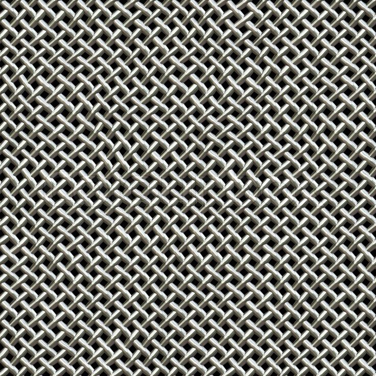
MIT engineers led by Hiroshi Ishii have developed a simpler method. It is based on the classic and most popular type of 3D printing - FDM or Fused Deposition Modeling. In this method, the printer's print head melts the filament and extrudes the melt through a nozzle, applying it to the substrate or previous layer. One of the features of the method is that the quality of application and retention of the material depends on its viscosity and extrusion volume. With some combinations of parameters, the application becomes uneven. In particular, with a low extrusion volume, a series of bumps can form, connected by a thread that does not touch the previous (lower) layer.
The authors decided to use this application mode to create a network structure, somewhat reminiscent of fabric. As a material, engineers used various substances, mainly PLA plastic. They conditionally compare the line passing through the tubercles with the warp, and the line formed by thin threads with the weft by analogy with the same structural elements in weaving.


