3D print inserts
Ultimate Guide to Threaded Inserts and 3D Prints
Download the full Guide
as a PDF!
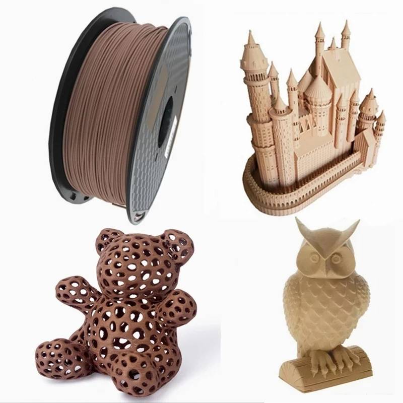
The simple post-processing techniques presented in this guide are an excellent way for professionals to create low-cost silicone molds, threaded inserts for enclosures, vacuum formed parts, and more.
Threaded brass inserts can be a great way to add longevity to 3D printed enclosures that need to accept screws.
In this “how to” we will show you some of the best practices associated with installing threaded brass inserts into your 3D printed enclosures.
Working time will vary depending on your model and how many inserts you plan to install. The process shown took us about 10 minutes from start to finish.
SUPPLIES
Soldering Iron
Threaded brass inserts with matching machine screws
Washers
Pliers
Vise
Heat resistant gloves
Eye protection
Respiratory mask
Need some of these products? We've curated an Amazon wish list for you.
STEP 1: OBTAIN YOUR MODEL
If you are designing your model to meet a specific need, remember to design the holes in your model slightly smaller than the inserts you plan to install. This will account for any plastic that melts when installing inserts. If you are adding inserts to a downloaded model, purchase your inserts with the hole diameter in mind.
For our model, we chose this “Light Switch Box” designed by Thingiverse user qbasan.
Manufacturers of threaded brass inserts specify the hole size needed for the insert.
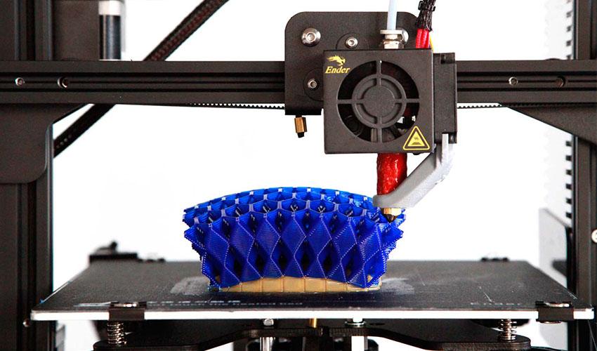
Step 2: Prepare & Print
When installing inserts, changing a few print settings in MakerBot Print can be a big help.
Increase the number of shells in your print. This will leave more plastic around inserts.
Once you have selected your settings you can print your object. We chose to print our model on the MakerBot Replicator+.
STEP 3: ROUGHING
Supplies Used: Needlenose pliers
Once your model has been printed and removed from the build plate, remove any rafts or support material.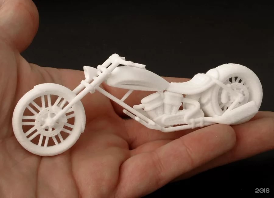
Supplies Used: Soldering Iron
Allow your soldering iron to heat for 3-5 minutes before installing inserts. This will ensure that you have to use the least amount of force to install inserts.
The 2021 Guide to 3D Printing Materials
Learn about polymers, composites, and metals all available for 3D Printing!
Supplies Used: Soldering Iron
Before installing your inserts, it’s also important that your model be secure. If your model moves during installation of an insert, you could damage the void or even the model itself.
We used a multi-axis vice that allowed us to work on the model from a few different angles.
Secure the model
Adjust the angle of the model
Supplies Used: (continued use through Step 9) Multi-axis vice, soldering iron, threaded brass inserts, and pliers
Because PLA has a relatively low heat deflection temperature and can deform at moderate temperatures, it is important to install inserts gradually.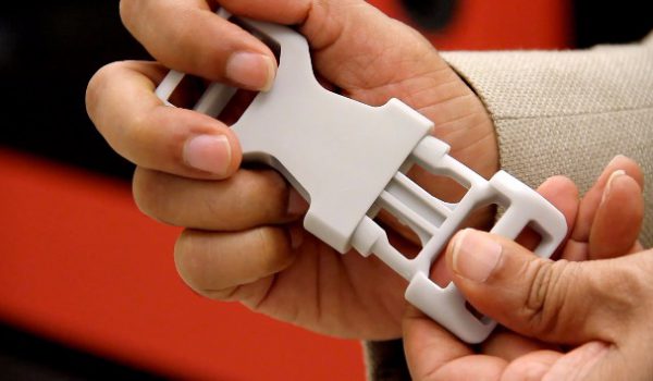
A: Grasp your insert with pliers
B: Position insert over hole
C: Press the insert half way into your print holding the soldering iron vertically
D: Move on to the next insert
Push lightly, your soldering iron should do most of the work for you
As brass transfers temperature relatively quickly, your inserts should be cool within a minute or so.
STEP 8: COMPLETELY INSTALL INSERTS
Once you’ve allowed your model to cool for a minute or so, install the inserts until they are flush with the top of your model.
When completing the installation of inserts be sure to avoid:
Installing too quickly
Pushing down on your inserts with too much force
Caution:
Never attempt to hold inserts in place with your hand when installing. Always use pliers.
Supplies Used:
Screws & washers
Screwdriver
Multi-axis vice
Thread in your screws using a screwdriver or drill.
Insert washers and screws
Insert additional hardware
Caution: Be sure not to over tighten.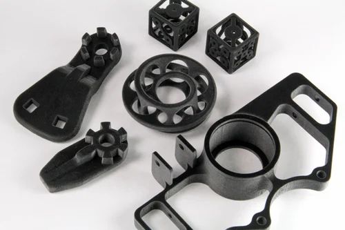 This can force the insert free from the surrounding plastic.
If you over tighten your screws, you may need to melt out your inserts and reinstall.
Here is our final part. After installing inserts, screws, and washers, we added the final switches to this electrical enclosure.
Visit one of our other applications pages for tips on how to take your print even further.
We recommend that you visit our pages on:
Vacuum Forming
Silicone Molding
Painting
Last but not least, remember to share your work with us on Thingiverse and social media @MakerBot.
We can’t wait to see what you make!
Light Switch Box
Qbasan
11/12/2014
https://www.thingiverse/thing:541876
Powered by MakerBot Learning.
Threading 3D Printed Parts: How To Use Heat-Set Inserts
We can make our 3D-printed parts even more capable when we start mixing them with some essential “mechanical vitamins.” By combining prints with screws, nuts, fasteners, and pins, we get a rich ecosystem for mechanism-making with capabilities beyond what we could simply print alone.
Today I’d like to share some tips on one of my favorite functional 3D-printing techniques: adding heat-set inserts. As someone who’s been installing them into plastic parts for years manually, I think many guides overlook some process details crucial to getting consistent results.
Make no mistake; there are a handful of insert guides already out there [1, 2]. (In fact, I encourage you to look there first for a good jump-start.) Over the years though, I’ve added my own finishing move (nothing exotic or difficult) which I call the Plate-Press Technique that gives me a major boost in consistency.
Join me below as I fill in the knowledge gaps (and some literal ones too) to send you back to the lab equipped with a technique that will give you perfectly-seated inserts every time.
Heat-Set Insert “Theory”
Heat-set inserts are stock parts that add threads to a part made from a thermoplastic. Since 3D-printing relies on oozing plastic out of nozzles, literally every single 3D-printed material fits the definition for thermoplastic–so they’ll all work! As far as matching techniques go, it’s almost like these inserts were made for each other! (Alas; they weren’t, but thankfully injection-molding plastic has made these parts a commodity.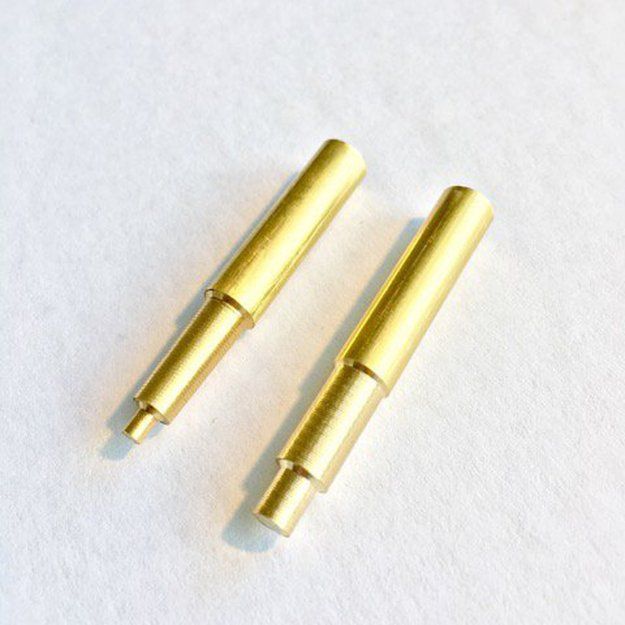 )
)
Heat-set inserts work by softening the surrounding material as they’re being installed. Once installed, removing the heat-source causes this molten plastic to re-solidify around the inserts’ knurled feature, holding it in place. Let’s consider thinking about this process in terms of heat transfer. Installation holes are smaller than the inserts themselves (they’re undersized), so we can’t install inserts by hand force. Rather, we first heat the insert and then conduct that heat into the surrounding material such that the hole deforms, accommodating the larger shape of the insert.
As more time elapses, heat transfers from the insertion tool, through the insert from surface area contact, and finally outwards into our 3D-printed part, where it dissipates. The longer time spent inserting the part, the more time the heat has to travel into the part where it can deform the surrounding part areas. In large scale manufacturing, this process is done by machine. In our case, though, we’re installing by hand, so we’ll need to keep our timing in mind.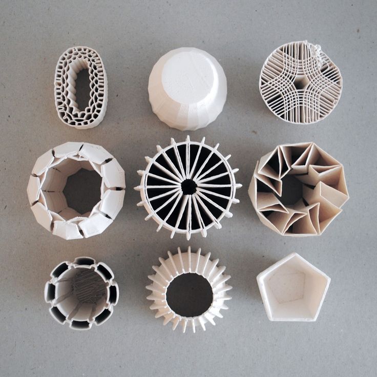 Finally, don’t forget that when we install the insert, we’re displacing molten plastic to make space for the heat-set insert. That displaced plastic needs to go somewhere, and it usually ends up mushed at the bottom of the insert.
There’s a Tool for That
Our tools need not be expensive. I use an insert “installation tip” combined with a budget 40W soldering iron from Amazon without any temperature control. These “installation tips” aren’t particularly special, but, unlike soldering iron tips, they aren’t tapered. Using a tip without a taper makes it easy to remove the tip once the insert is installed.
“Inserts” for a soldering iron. Image Source: Virtjoule on TindieYou can find inserts on McMaster-Carr (pn: 92160a115) or on Tindie. (I admit that I use the McMaster-Carr one for 4-40 and M2.5 inserts, but also with M3, M4, and M5 inserts without any issues!)
I strongly discourage using a vanilla soldering iron tip for the following reason. Most of these tips are tapered. If we use a tapered soldering iron tip, we risk getting the iron tip stuck in the insert. Remember: metal expands when it heats up and contracts when it cools. As we install the metal insert into the printed part, we’re dissipating heat from the insert into the part, causing the heated insert to cool slightly and also contract around the iron tip. The net result is that when we try to pull the iron tip out, the insert comes with it! I imagine that this scenario is akin to a Chinese finger trap.
All that said, this problem wouldn’t happen too often for me back when I used a vanilla soldering iron tip for this process, but 1-out-of-5 ruined prints was enough for me to scrounge up the extra $10 and get the right tip.
Finally, my last tool for this process is a small square of thin sheet-metal, about 150x150mm (6″x6″). This sheet becomes a “flat” reference that I’ll discuss in the process later.
Designing for Inserts:
When it comes to sizing holes for inserts, I’d recommend following the dimensional info that comes with the insert datasheets. As a quick reference, here’s a mini compendium of links for some of my go-to inserts and their hole size recommendations.
- UD-43030 short M3x0.5 insert (relevant dimensions, vendor)
- 94180A331 M3x0.5 tapered insert (relevant dimensions and vendor)
- 93365A120 #4-40 tapered insert (relevant dimensions and vendor)
To accommodate displaced material, I suggest increasing the hole depth by about 50% of the insert length. This change ensures that the displaced plastic has somewhere to go and doesn’t fill up the cavity where the insert should be.
Other guides suggest adding a small taper to the hole feature. This is a nifty feature that enables inserts to seat themselves into the hole before installing them with heat. Some inserts are themselves tapered, which has the same seating effect on an un-tapered hole. Adding this tapered feature (or buying the slightly-more-expensive tapered inserts) isn’t necessary, but it does make the installation process easier.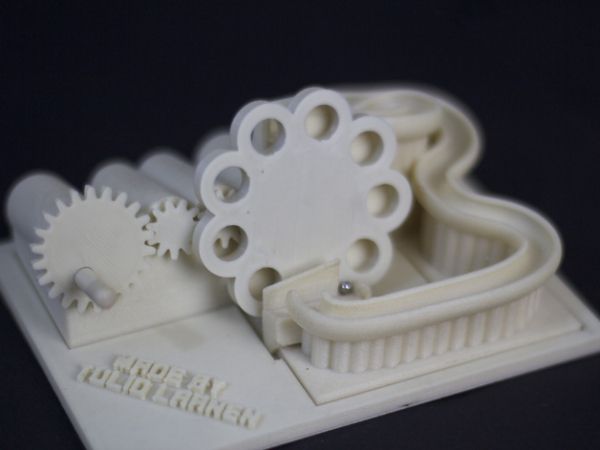
Slicer Settings:
With a design ready-to-go, I’d recommend tweaking one 3D-printer Slicer setting first, namely the perimeter layers. Slic3r defaults to two perimeter layers for hole features. I’d recommend bumping this value up to at least 4 perimeters for two reasons.
4 perimeter layers for added structure and reduced sink marksFirst, we want to make sure that our installed insert is still “grabbing” onto material after we install it. An installed insert displaces material outwards during installation, so adding layers improves the odds that we haven’t melted through it upon installation.
Second, adding more perimeter layers also reduces the extent to which external indentations form on the part when inserts are situated close to the external surface of a part. These indentations are called sink marks, and they’re actually a common problem found in injection-molded parts too. Sink marks occur because a part contracts as it cools. I’ve discovered that adding more perimeters reduces this effect. I can’t say for sure why this is the case, but my best guess is that adding solid material reduces the free space inside the part, making it more difficult for internal geometries to change shape.
The Installation Process and the Plate-Press Technique:
Now that we’ve got a handle on designing and prepping parts for inserts, let’s get to the installation procedure.
First, make sure that your soldering iron has completely reached its set temperature before using it to install inserts. If we try installing an insert while the iron is still rising to its setpoint, the process just takes longer, and all that heat from the iron is spending more time diffusing into our part, causing it to warp.
Next, with the insert positioned in the hole, apply heat to the insert. Let the weight of the soldering iron tool itself apply the gentle force needed to push the insert into position.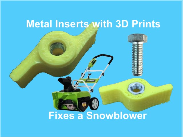 Gravity should be doing most of the work here. This process takes about 10-15 seconds. Keep applying heat until your insert is about 90% seated into your part.
Ok, here’s where we derail from convention. With the insert at about 90% into you part, remove the iron and quickly flip the part onto a flat, heat-resistant surface and gently push the part down until it seats flush with the material. (I use a small piece of sheet metal for this step.) Wait about 6-10 more seconds for the part to cool, and you’re done! I’ll call this maneuver the plate-press technique.
This final step of the process seems odd, but it’s critical for two reasons. First, it seats the insert so that it’s both vertical and completely flush with the top of the printed part. Second, it flattens any bulging material that flared up while we were installing the insert.
Results
If all went well, you should have a nice-looking insert that’s flush with the part surface. In the image below, I used the iron to seat these parts most-of-the-way in and then cooled them flush with the plate-press technique.
In the next example below, this insert was set without using the plate-press technique. Notice that nasty “bulge” of excess material that beads up around the insert. That’s precisely the bulge that we can remove when we use the final plate-press technique.
Reflection:
I imagine that tweaking both our iron temperature and insertion speed might reduce or eliminate this bulging effect if we practice installing these inserts under various conditions. But that hypothetical need for practice is exactly what makes the plate-press technique so valuable. Simply put, the plate-press technique gives us consistent results without the need for robot-levels-of-precision. We simply “smoosh” the insert into its final place and be done with it. The result is a flush insert with little effort and no practice. Admittedly, this technique is not how the industry folk do it for mass-production, but it sure is consistent — a hack even.
Conclusion:
That’s it! I hope this guide serves you well in nailing beautiful flush inserts every time without too much hand hassle. Here’s a quick snippet of a few other parts I made to put some perspective on what to expect.
I’ve started posting my wares up with #beautifulinserts, and I’d love to see how this technique fares for you. If you make anything fun, why not inspire some fellow community members by joining the conversation?
References:
- https://markforged.com/blog/heat-set-inserts/
- https://www.ptonline.com/articles/four-ways-to-tackle-threaded-inserts-for-plastics
3D Printer Threads and Thread Inserts for Plastic
At Formlabs, we design various functional parts for printing on our stereolithographic (SLA) 3D printers such as the Form 3. These parts include prototypes used for our own R&D, clamps and fasteners to be used on our production lines, models to check the design before casting the final product in the appropriate material, such as nylon. nine0003
Regardless of the application, we often need to connect 3D printed components with screws and threaded fasteners. As the catalog of versatile and reliable engineering polymers grows, the differences between "imitation" prototypes and functional prototypes diminish.
This article is a guide to threading and threading 3D parts with a 3D printer. There are many ways to connect multiple 3D printed parts together, but if you need the ability to repeatedly connect and disconnect components and secure mechanical fastening, there is no real substitute for metal screws. nine0003
Do you like to see everything with your own eyes? Watch a video about 3D printing threaded connections and threaded inserts for 3D plastic parts.
White Paper
Download our white paper on stereolithography to find out how SLA printing works, why thousands of professionals use it today, and how this 3D printing technology can be useful in your work.
Download white paper
Let's take a look at some of the threading options for 3D parts we've put together based on years of Formlabs experience and your suggestions.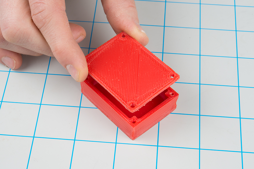 We've ranked these options, starting with the one we think is the best, with the pros and cons of each option for different use cases. nine0003
Experience Formlabs print quality first hand. We will send a free 3D printing sample directly to your office.
Request a free sample
Benefits: Strongly connects 3D printed parts without the use of glue. The metal threads are durable and reusable.
Drawbacks: Inserts may loosen as temperature rises.
3D print a sleeve blank with a depth and diameter that matches the insert specifications. Rinse with isopropyl alcohol (IPA) and allow to dry without final polymerization. Insert the insert into the sleeve with a screwdriver and use the screw to secure it completely into the plastic. Then finish curing the part to reduce the creep effect and fix the insert in the plastic even better. Performing this step last reduces the chance that the insert will break the sleeve when screwed in.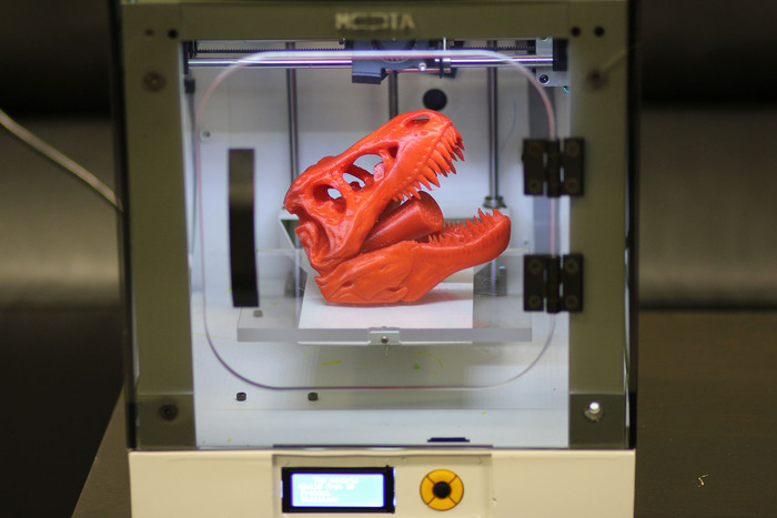 nine0003
Benefits: Connects 3D printed parts very securely. The metal threads are durable and reusable.
Cons: Adhesive required (don't try to use a soldering iron!).
Threaded inserts with heat setting are designed for installation in thermoplastics using a soldering iron with a soldering tip. They can be used in acrylic models and Fused Deposition Models (FDM), but cannot be installed in SLA photopolymer parts, which bend but do not melt when heated.
Check out our detailed guide comparing FDM vs. SLA 3D printers to see how they differ in terms of print quality, materials, application, workflow, speed, cost, and more.
However, the notches and ridges on the heat set inserts make them a very effective thread fastener if you bond them with a two part epoxy or cyanoacrylate adhesive. Determine the bushing size by the largest diameter of the insert and apply some adhesive before installation.
For best results, the part must be completely dry and cured. nine0003
Benefits: Nuts are easy to match to any required screw size.
Drawbacks: Side nut slots can eliminate the need for glue, but can make it harder to support the model during printing.
Adding a hexagon socket to the nut press-fit end creates a reusable strong metal-to-metal connection. To increase the twisting force, you can choose a square nut. This nut can also be plastic or have blocking elements. If necessary, a drop of cyanoacrylate glue will help hold the nut in place, but if the design includes a side socket, there is no need for glue. Use a 0.1 mm offset around the press-in nut and clearance around the screw itself. nine0003
Benefits: Prototyping uses the same metal products as mass-produced injection molded parts. Sleeve blanks made from Tough (and Durable) polymer are unlikely to crack if you follow the screw manufacturer's sleeve design guidelines.

Disadvantages: The screws will hold tight, but the threads will not be as resistant to repeated use as metal threads. Standard resins can be used, but the bushing is more likely to crack. nine0003
Follow manufacturer's recommendations for core sizes and print with high impact engineering resins (such as our Tough Resin and Durable Resin). Before using the screws, complete the final curing. If you are prototyping an injection molded part that will use tapping or tapping screws in its final assembly, this is a good option for testing.
Benefits: No need to buy special plastic screws. nine0003
Disadvantages: The screws will hold tight, but the threads will not be as resistant to repeated use as metal threads.
We have tested screws in our Tough Resin product and found that their use is identical to that of threading screws designed for plastics. The size of the hole diameter of the threaded bushing must be in the range between the main (threaded) diameter of the screw and the inner diameter.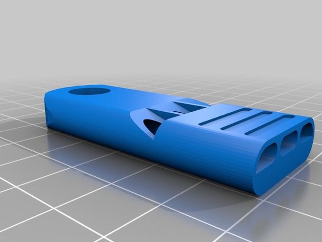 The screw shown is a #8 screw in a 0.16" diameter hole. nine0003
Benefits: Can be used for prototyping large and custom threaded designs.
Disadvantages: Not a durable or reusable fastening solution, especially for smaller thread sizes.
3D printed threads from standard resins are better than Tough Resins because they are much harder. 3D printed threads remain relatively brittle, depending on the size of the thread, and are not recommended if the fastening system is to be used continuously and repeatedly. nine0003
Thread sizes ¼-20 or larger are generally functional without the need for post-processing. For smaller screws, the threads must be modified to provide better fastening. For example, printing a round thread profile (on a screw and a nut) and using a 0.1mm offset results in a better thread fit and improved wear characteristics. For all screw sizes, it is best to orient the parts so that the supporting structures do not touch the threads.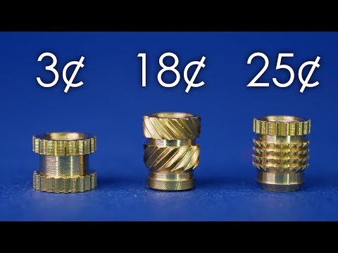
White Paper
Tolerance and fit design reduces post-processing time and simplifies assembly, as well as reduces material costs per iteration.
Learn more
We hope this guide has provided you with useful information about the mechanical mounting options that can be used for 3D printed components! If you are interested in seeing the model we use for testing, please download the STL file.
Download STL file
Parts mentioned in this manual can be ordered from McMaster using the links below:
- M3 insert with heat setting for plastic
- Brass M3 screw-in insert for plastic
- Galvanized steel hex nut M3
- Galvanized steel hex nut M4
- Threading screw 4-20 for plastic
Want to try Tough Resin, Durable Resin or any other Formlabs 3D printing material in action? Request a free sample! nine0003
Request a free sample SLA
Threaded connections in 3D models
Miscellaneous
Subscribe to
Subscribe
I do not want
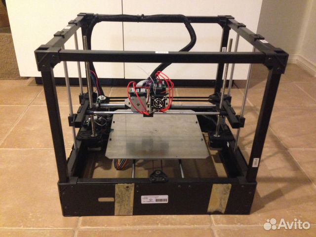
9000 86 Often when printing one or another complex model, for example, a case or a mounting bracket, the task arises to use a threaded connection, so that it would be convenient to repeatedly assemble / disassemble the final product in the future.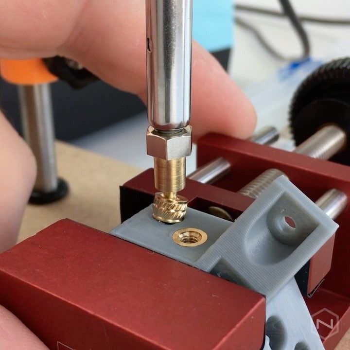 nine0003
Of course, the first and perhaps the simplest solution is to cut the thread with a tap in plastic. But such connections usually withstand a small number of assembly / disassembly cycles. This is especially true when a prototype is being developed, where in the process of its creation a large number of assembly and disassembly cycles occur with constant fine-tuning of certain nodes.
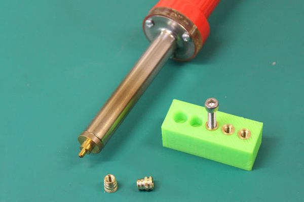
Surely many people already know about insert nuts and use them in their practice. But I'm sure many novice printers didn't even look in that direction. I can only add that in some cases, the use of such nuts is very simple and convenient, and installing them in the model is not difficult. To do this, you need a regular soldering iron, with which such nuts can easily fit into pre-prepared holes. nine0003
In my work, in most cases, I use such fasteners, it allows you to repeatedly assemble or disassemble the prototype, while the connection remains strong.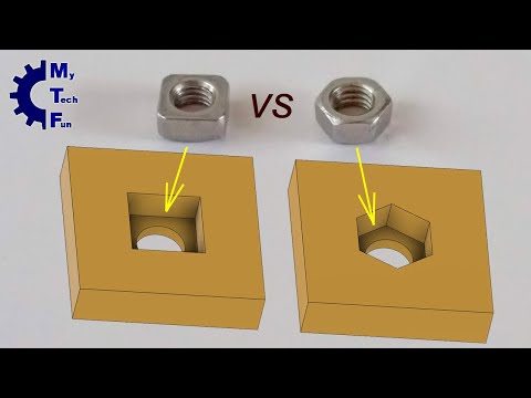 It does not have to be repaired by pouring dissolved plastic if ABS is used.
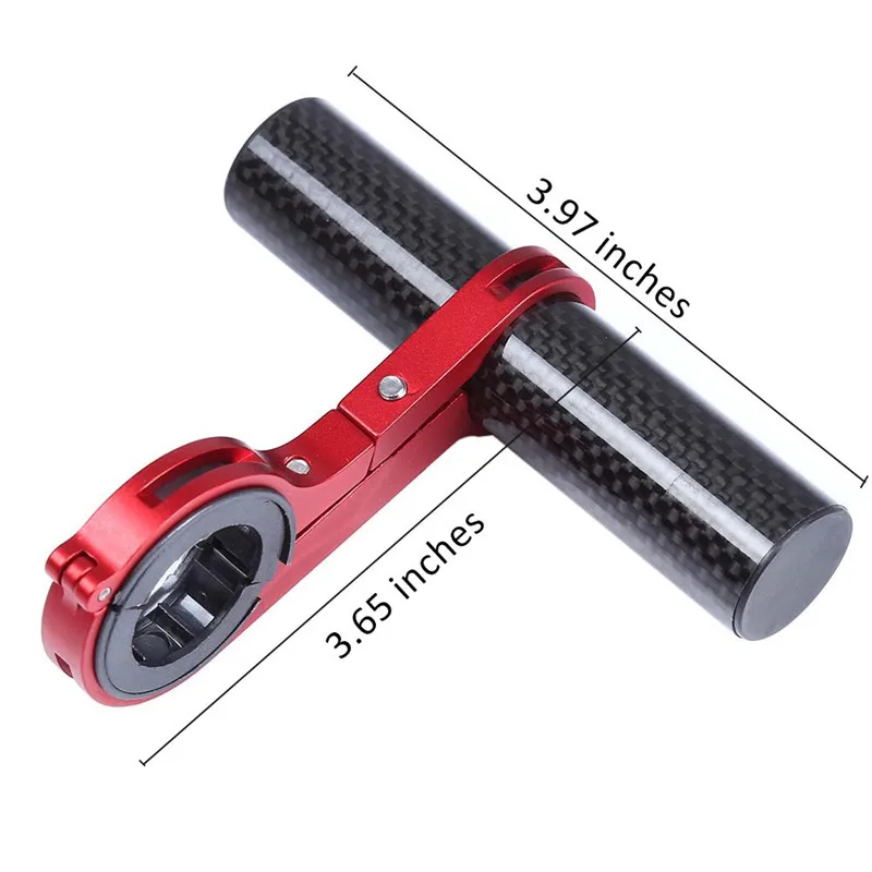
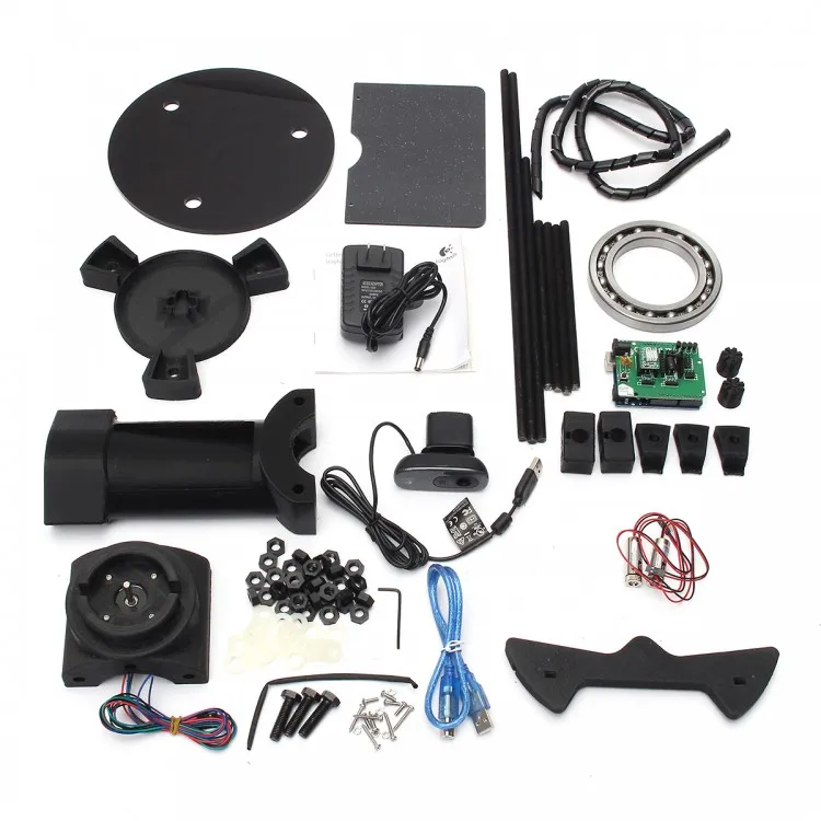
Following the link to the video, an example of using nuts-inserts, this is a prototype of a table for photographing objects at 360 degrees https://www.youtube.com/watch?v=Hnw2Jbkh3c0 (see from the second minute), you can also see the process there installing these nuts. The table during the development process had to be disassembled and reassembled so many times that it was impossible to count, and of course there was no damage to the layout. nine0003
And these are just a few photos with examples of application:
(top is cooling for MKS-Base, the model can be viewed here: link )
where the direction of the teeth is in different directions. The second type is better, but also more expensive, sometimes significantly. I settled on straight lines, the simplest. They are pretty solid in the plastic. These nuts are also divided into 2 types: with a through threaded hole and a deaf one. They can also be used to create handle nuts (see below)...
It is also often necessary to use nylon or brass posts. In our market, their price for 1 piece is like in China for a dozen, or even a hundred. Therefore, I recommend looking in this direction.
These are just some examples, I am sure those who wish will find fasteners of any shape for every taste and size.
Insert nut (brass) - https://goo.gl/CmzUnT
steel - https://goo.gl/n89ItyHex socket head screws in stainless steel round head steel - https://goo.gl/Xz1MDe
Nylon racks (set) - https://goo.gl/icVivB
Buying through the CashBack system will be cheaper! More details here - https://cashback.epn.bz/ru/
Of course, one cannot fail to note the frequently used method of threading with a regular hex nut, as in the following example:
(part of a vice for mini CNC, the model can be viewed here: link)
But such a connection requires additional space/thickness and an undesirable structural weakening of the wall of the object in order to place its nut inside.