Z banding 3d print
5 Ways How to Fix Z Banding/Ribbing – Ender 3 & More – 3D Printerly
Most 3D printer users have experienced Z banding or ribbing issues at some point in their 3D printing journey, same with me. I wondered though, how do we fix this Z banding issue, and are there simple fixes out there?
The best way to fix Z banding in your 3D printer is to replace your Z-axis rod if it is not straight, enable consistent bed temperature with PID, and use layer heights which avoid your 3D printer using microstepping. A faulty stepper motor might also cause Z banding, so identify the main cause and act accordingly.
These fixes are fairly easy to do but keep on reading for more key information. I’ll give you a detailed description on how to do them, as well as what to look out for and other tips to fix Z banding issues.
If you are interested in seeing some of the best tools and accessories for your 3D printers, you can find them easily by clicking here.
What is Z Banding in 3D Printing?
Many issues in 3D printing are aptly named after what they look like, and banding is no different! Z banding is a phenomenon of bad 3D print quality, which takes on the visual of a series of horizontal bands along a printed object.
It’s pretty easy to figure out whether you have banding just by looking at your print, some being a lot worse than others. When you look at the image below you can clearly see the thick lines with dents which look like actual bands on the print.
In some cases, it can look like a cool effect in some prints, but most of the time we don’t want Z banding in our objects. Not only does it look rigid and imprecise, but it also causes our prints to have a weak structure, among other downsides.
We can determine that banding is not an ideal thing to be happening, so let’s look into what causes banding in the first place. Knowing the causes will help us determine the best ways to fix it and prevent it happening in the future.
What Causes Z Banding in Your Prints?
When a 3D printer user experiences Z banding, it’s usually down to a few main issues:
- Bad alignment in the Z axis
- Microstepping in stepper motor
- Printer bed temperature fluctuations
- Unstable Z axis rods
The next section will go through each of these issues and try to help with fix the causes with a few solutions.
How Do You Fix Z Banding?
You might have tried several things to fix Z banding, but they just aren’t working. Or you have recently discovered it and searched for a solution. Which ever reason you came here for, this section will hopefully give you the guidance to fix Z banding once and for all.
The best way to fix Z banding is to:
- Correctly align the Z axis
- Use half or full step layer heights
- Enable a consistent bed temperature
- Stabilize Z axis rods
- Stabilize bearings and rails in other axes/print bed
The first thing you should look at is whether the banding is uniform or offsetting.
Depending on the exact cause, there will be different solutions that you should try first.
For example, if the main cause is from a 3D printer wobble or uneven movement from the rods, your banding will look at certain way.
The banding here would be where each layer slightly shifts in a certain direction. If you have Z banding which mostly comes out on just one side, it means the layer should be offset/depressed on the opposite side.
When the cause of your Z banding is to do with layer heights or temperature, you are more likely to get a banding which is uniform and equal throughout.
In this case, layers are wider in all directions compared to another layer.
1. Correctly Align the Z Axis
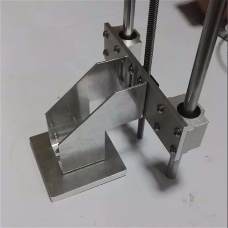
The video above shows a case of a poor Z-carriage bracket that holds the brass nut. If this bracket is badly manufactured, it might not be as square as you need it to be, resulting in Z banding.
Also, the screws of the brass nut shouldn’t be fully tightened.
Printing yourself an Ender 3 Adjustable Z Stepper Mount from Thingiverse can help out a lot. If you have a different printer, you can search around for your specific printer’s stepper mount.
A flexible coupler also works well to get your alignment in order, to hopefully eliminate the Z banding you have been experiencing. If you are after some high quality flexible couplers, you’ll want to go with the YOTINO 5 Pcs Flexible Couplings 5mm to 8mm.
These fit a wide range of 3D printers from Creality CR-10 to Makerbots to Prusa i3s. These are made of aluminum alloy with great craftsmanship and quality to eliminate the stress between your motor and the drive parts.
2. Use Half or Full Step Layer Heights
If you choose the incorrect layer heights, relative to your 3D printer’s Z axis, it can cause banding.
It is more likely to show up when you are printing with smaller layers since the error is more pronounced and thin layers should result in pretty smooth surfaces.
Having some incorrect microstepping values can make it harder to fix this issue, but luckily there is an easy way to get around this.
When you compare the movement precision of the motors we use, they move in ‘steps’ and rotations. These rotations have specific values of how much they move, so a full step or half step moves a certain number of millimeters.
If we want to move at even smaller and more precise values, the stepper motor has to use microstepping. The downside of microstepping though, is the movements aren’t as precise as we want them to be.
It is easy to avoid your extruder having to use microstepping by using either the full or half-step values for your 3D printer, relating to layer heights.
I did a recent post which has a section about microstepping/layer heights and its ability to give you better quality prints.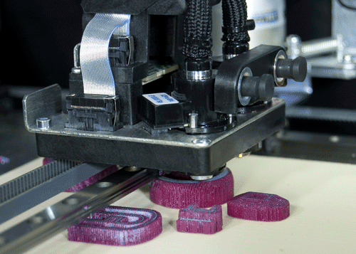
Basically, with an Ender 3 Pro 3D printer or Ender 3 V2 for example, you have a full step value of 0.04mm. How you use this value is by only printing in layer heights that are divisible by 0.04, so 0.2mm, 0.16mm, 0.12mm and so on. These are known as ‘magic numbers’.
These full step layer height values mean you don’t have to kick into microstepping, which can give you uneven movement throughout the Z axis. You can input these specific layer heights into your slicer, whether using something like Cura or PrusaSlicer.
3. Enable a Consistent Bed Temperature
A fluctuating bed temperature can cause Z banding. Try printing on tape or with adhesives and no heated bed to see if you still experience Z banding on your prints. If this solves the problem, then it’s probably an issue with temperature fluctuations.
Source | RepRapThe two types of bed heating processes are called Bang-Bang bed heating or PID bed heating. Bang-Bang bed heating is when your 3D printer reaches the set bed temperature and stops heating, which then causes it to cool down.
The bed then hits a certain point below the set bed temperature then kicks in again to hit the set temperature. Bang-Bang, referring to hitting each of those temperatures several times.
This can result in your heated bed expanding and contracting, at a level just high enough to cause print inconsistencies.
PID (Proportional, Integral, Differential terms) is a loop command feature in Marlin firmware to autotune and regulate bed temperatures to a specific range and stops wide temperature fluctuations.
This older video from Tom Sanladerer explains it pretty well.
Turn on PID and tune it up. There can be confusion when using the M303 command when identifying the extruder heater versus the bed heater. PID can keep a good, consistent temperature of your bed throughout a print.
The heating cycles of the bed fully turn on, then cool down before starting back up again to reach your overall set bed temperature. This is also known as bang-bang bed heating, which happens when PID isn’t defined.
In order to solve this, you need to adjust a few lines in Marlin firmware’s configuration.h:
#define PIDTEMPBED
// … Next section down …
//#define BED_LIMIT_SWITCHING
The following worked for an Anet A8:
M304 P97.1 I1.41 D800 ; Set the bed PID values
M500 ; Store to EEPROM
This isn’t on by default because some 3D printer designs don’t work well with the rapid switching that occurs. Make sure before doing this that your 3D printer has the capabilities to use PID. It’s automatically on for your hotend heater.
4. Stabilize Z Axis Rods
If the main shaft isn’t straight, it can cause a wobble which results in bad print quality. Bearing at the top of each threaded rod contributing to banding, so it can be a series of causes that add up to make banding as bad as it is.
Once you identify and fix these causes of banding, you should be able to eliminate this negative quality from affecting your prints.
A bearing check on the Z rods is a good idea. There are rods out there straighter than others, but none of them would be perfectly straight.
When you look at how these rods are set up on your 3D printer, they have the potential to not be straight, which offsets the Z axis slightly.
If your 3D printer is clamped in bearings, it can be off-center since the hole where the rod fits through isn’t the perfect size, allowing for extra unnecessary movement side to side.
These side to side movements cause your layers to be misaligned which results in the Z banding that you are familiar with.
Caused by a poor alignment of the plastic bushings on the extruder carriage. This increases the presence of vibrations and uneven movements throughout the printing process.
For such a cause, you would want to replace the ineffective rails and linear bearings with hardened rails and high quality bearings. You might even want a metal extruder carriage if you have a plastic one.
If you have two threaded rods, try slightly rotating one of the rods by hand and see if they are both synced up.
If the Z nut is higher up on one side, try to slightly loosen each of the 4 screws. So, basically trying to get an equal angle on each side, so the movements aren’t unbalanced.
5. Stabilize Bearings & Rails in Other Axis/Print Bed
The bearings and rails in the Y axis can also contribute to Z banding so definitely check over these parts.
It’s a good idea to do a wiggle test. Grab your printer’s hotend and try wiggling it to see how much movement/give there is.
Most things will move a little bit, but you are directly looking for a large amount of looseness in the parts.
Also try the same test on your print bed and fix any looseness by shimming your bearings into better alignment.
For example, for the Lulzbot Taz 4/5 3D printer, this Anti Wobble Z Nut Mount aims to eliminate minor Z banding or wobble.
It doesn’t require a firmware update or anything, just a 3D printed part and a set of materials that attach to it (described on the Thingiverse page).
Depending on the design of your 3D printer, you might be more likely to experience Z banding. When the Z axis is secured with smooth rods, along with threaded rods which have bearings on one end that move it up and down, you won’t have this problem.
Many 3D printers will use the combination of a threaded rod connected to your Z stepper motor shafts to hold it in place through its internal fitting. If you have a printer with a platform carried by the Z axis, you can experience banding through wobble of the platform.
Other Solutions to Try Fix Z Banding in 3D Prints
- Try putting some corrugated cardboard underneath your heated bed
- Put the clips that hold your bed in place right at the edge
- Ensure that aren’t any drafts that affect your 3D printer
- Screw up any loose bolt and screws in your 3D printer
- Make sure your wheels can move freely enough
- Decouple your threaded rods from smooth rods
- Try a different brand of filament
- Try increasing the minimum time for a layer for cooling issues
- Grease your 3D printer for smoother movements
There are many solutions to try out, which is common in 3D printing but hopefully one of the main solutions works for you. If not, run down a list of checks and solutions to see if one of them works out for you!
Best Z Banding Test
The best test for Z Banding is the Z Wobble Test Piece model from Thingiverse. It’s a vertical cylinder that you can 3D print to see whether you are actually experiencing Z Banding or not.
One user realized that his Ender 5 had really bad horizontal lines, so he 3D printed this model and it came out bad.
After doing a series of fixes such as disassembling his Z axis, cleaning and lubing it, checking how it moves, and realigning the bearings and POM nuts, the model finally came out without the banding.
If you love great quality 3D prints, you’ll love the AMX3d Pro Grade 3D Printer Tool Kit from Amazon. It is a staple set of 3D printing tools that gives you everything you need to remove, clean & finish your 3D prints.
It gives you the ability to:
- Easily clean your 3D prints – 25-piece kit with 13 knife blades and 3 handles, long tweezers, needle nose pliers, and glue stick.
- Simply remove 3D prints – stop damaging your 3D prints by using one of the 3 specialized removal tools
- Perfectly finish your 3D prints – the 3-piece, 6-tool precision scraper/pick/knife blade combo can get into small crevices to get a great finish
- Become a 3D printing pro!
I hope this article helps you out. Happy Printing!
3D Printer Z Banding – Common Causes and Fixes! – 3dprintscape.com
No matter how well you set your printer up, it’s still highly likely that you’ll experience print defects from time to time. After months of use, screws can loosen and gantries can go out of alignment.
Z banding, or “ribbing”, is one of the least common issues you’ll encounter, but I noticed a few people asking about it. So I decided to write this article which goes through every possible cause of Z banding and how to fix it.
Some of the advice here applies to the Ender 3 but if you have a different printer, most of the information here will help you as well.
What Is Z Banding In 3D Printing?
Z Banding in 3D printing is a defect in the Z axis that causes print layers to protrude from the part. So the part ends up with obvious layer lines that ruin the appearance of the print. Z banding makes it impossible to print parts with a smooth finish. It’s a print defect found in FDM printers caused by multiple factors which I’ll cover shortly.
Z banding occurs when the printer doesn’t move straight up and down the Z axis during a print. This is caused mostly by lead screws or motor shafts that are bent. Loose screws are also a common cause of defects like Z banding.
What Does Z Banding Look Like?
Z banding looks like lines or ribs on a print where it should be smooth. Z banding is usually the appearance of a uniform pattern in print layers that stick out from the part. Sometimes, Z banding looks like a bulge around the part in only a few layers, with the rest of the model looking normal. Z banding results in a ribbed surface instead of a flat one.
Causes Of Z Banding In 3D Printers And How Fix It
There are a lot of reasons Z banding could occur. I’ll explain the most common causes and then go over how to resolve them.
Loose screws on the X axis gantry
Loose screws on the X gantry causes Z banding because both sides of the gantry don’t move together properly. This is a bigger problem with single Z axis screw printers compared to dual lead screw machines.
Solution: Tighten the screws that connect the X gantry to the Z rail on the left
Here are the steps on how to tighten the appropriate screws on an Ender 3, but it’s very similar for most FDM printers.
- Unplug the printer for safety reasons.
- Unscrew the four screws at the top of the Z gantry.
- Remove the Z gantry from the top of the printer.
- Manually raise the X gantry from the printer. (The extruder gantry)
- Tighten the screws on the left side of the gantry.
- Put the Z gantry back into the printer and tighten the top screws.
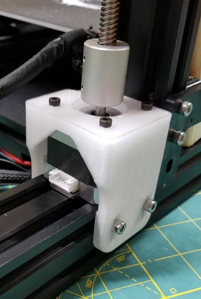
Screw rod coupler is skew
A skew coupler will cause Z banding because it puts the lead screw out of alignment.
Solution: Straighten and tighten the coupler on the lead screw
Unscrew the two screws on the coupler and remove it from the lead screw. Put a spacer of around 1cm at the bottom of the lead screw and then tighten the coupler back on. Remove the spacer after screwing the coupler on.
Once you’ve attached the coupler, print a Z motor spacer and attach it below the coupler to prevent Z binding.
Screws on X gantry are too tight
X gantry screws that are too tight cause binding on the Z axis. This is because the X gantry can’t move up and down the Z axis smoothly with over tightened screws.
Solution: Loosen the elliptical nut on the X axis gantry
If you have a 3D printer like the Ender 3, you might need to loosen the nut on the X axis gantry.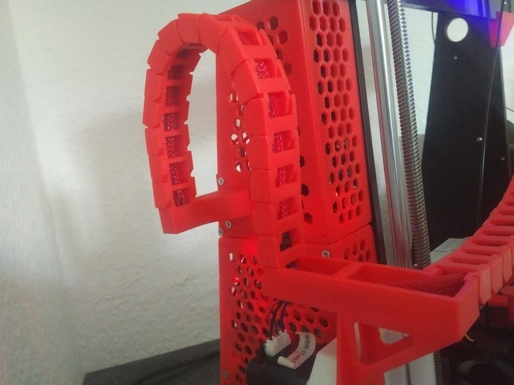 If it’s too tight, it causes binding on the Z axis. To test if it’s tight enough, gently move the X gantry up and down with your hand. There should only be a couple of millimeters of play. It needs to be tight enough to reduce the play but also loose enough to allow the X gantry to move up and down with the Z axis accordingly.
After tightening, manually move the X gantry up and down the lead screw to make sure it’s not too tight.
The X gantry sags on the side without a lead screw
For printers that only have one lead screw, the X gantry can sag on that side. So the one side of the X axis will be a bit lower than the other.
Solution: Add an additional Z axis lead screw
Having the X axis gantry supported by a lead screw on one side only is problematic because it causes a bit of sagging on the side without a lead screw. This is especially bad if you plan to upgrade the hot end and therefore increase the weight for the gantry to support.
If tightening the screws doesn’t decrease the sag, rather upgrade your printer with an additional lead screw and stepper motor. This is also a good idea if there is no sag, but binding still occurs.
A dual lead screw upgrade will make your printer a lot more accurate and stable during prints, so you won’t only be fixing the Z banding, you’ll be increasing the printer’s overall performance.
Upgrade kits like these on Amazon will give your printer more accuracy and remove the play on the side that didn’t have a lead screw. This upgrade will also enable you to print at higher speeds with less wobble.
Filament not feeding through freely
Filament that’s not feeding freely into the extruder can cause Z banding because the filament pulls the extruder upwards and puts it out of alignment. Then the filament causes the X axis gantry to fall back into position when it manages to feed through again. This process repeats throughout the print, which causes the Z banding.
Solution 1: Add a filament guide
A filament guide will help the filament feed through the printer freely. It’s not a very complex part, so you should be able to print it even if you have some Z banding. Then you can print a good-looking one with the imperfect guide attached and swap them out.
Solution 2: Add a filament tube
Filament feed tubing also helps to feed the filament through in a uniform and controlled manner. There are a variety of tubes available like these ones on Amazon, so you can check which one suits your budget.
Bent lead screw
A bent lead screw is a major cause of Z banding because, as the screw turns, it moves the extruder in and out of the print incorrectly.
Solution: Replace the lead screw
Luckily, lead screws are widely available. You’ll need to check the dimensions of your lead screw to make sure you purchase the right size. To check if your lead screw is bent, remove it from the printer, place it on a flat surface and roll it over. It should roll smoothly across the surface and you’ll notice if it’s bent when it rolls with a wobble. Here are a few different lead screws on Amazon.
Bent stepper motor shaft
If the stepper motor shaft is bent, it will cause the Z axis to wobble constantly because it’s directly connected to the lead screw.
Solution: Replace the stepper motor
The best thing to do is replace the stepper motor if the shaft is bent. Here is a range of stepper motors on Amazon for you to look through. Just check the compatibility with your printer before making the purchase.
Loose stepper motor
A loose stepper motor will cause unwanted movement on the Z axis, especially with faster prints.
Solution: Tighten the stepper motor screws
Tighten the screws of the stepper motor just enough for it to have no movement when you move it with your hand. Don’t make it too tight or you’ll get a different variation of Z banding.
Dirty Z lead screw rods
Over time, the lead screws can gather dust, especially because it sticks to lubricants that should be on the screw. Dust is very abrasive and can cause the movement of the Z axis to be restricted. Dust can even damage the threading of the lead screw if you don’t clean it off from time to time.
Solution: Clean the lead screw
There are many ways to clean the lead screw, but I find the best way is with isopropyl alcohol because it strips any lubricant away, along with the dirt. I suggest pouring some of the cleaning agent into a small container and then dabbing a brush into it to brush off the dirt from the screw.
Remember to add lubricant again once you’re done cleaning the lead screw. I cover the full process in this video.
Inconsistent extrusion
Inconsistent extrusion can cause defects that look similar to Z banding. However, extruder feed problems usually create random ribbing and other defects on the part, whereas Z wobble or Z banding creates regular patterns of Z banding. If the ribbing on your print is random, inconsistent extrusion could be the cause. These are some ways you can fix it.
Solution 1: Clean the nozzle out
I only clean the nozzle out if it’s a more expensive one, like a hardened “high-quality” nozzle. Having said that, cleaning a nozzle is relatively simple. Here’s a video I made on how to do it.
Solution 2: Replace the nozzle
If you’re still using the stock nozzle and it’s clogged up, I suggest buying a higher-quality hardened nozzle like these ones on Amazon. You’ll get better printing performance from them and they last a lot longer than weak stock nozzles. Here’s another video I made on how to install them.
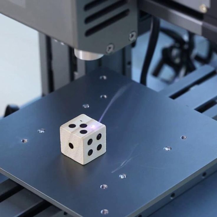
Z Banding Test
The best way to test for Z banding is to print a smooth surface cube. If you see Z banding patterns which look like fat print layers instead of a smooth surface, you have Z banding issues.
Here’s a detailed cube on thingiverse that you can print to test for Z banding on your printer.
How To Remove Z Banding Defects
To remove Z banding defects from a part, there are a few different things you can do.
Sanding
One of the easiest and most common ways of removing print defects is by sanding them away. Start with a low grit paper around 300 to 500 in the beginning and work your way to high grit paper like 2000 to finish the job off.
Wet the sandpaper before using it to polish the part. This will reduce heat generated by the friction of sanding and it gives the part an extra smooth finish.
If you’re polishing a flat area of the print, use a sanding block to prevent digging grooves into your part.
Try to sand the part in circular motions to avoid obvious sanding lines.
Related Articles
- Bed Leveling Issues – Common Causes and Fixes
- 3D Printer Speed VS Quality
- 3D Printer Nozzles (Detailed Overview)
- How Do You Resume A 3D Printer After Power Loss?
- Create a Temperature Tower Using Cura – The Easy Way
- Cura Profiles
Conclusion
Z banding in 3D printers almost always occurs due to misaligned parts in the printer. Parts become misaligned when screws come loose or if parts are bent. So it’s fair to say that you can eliminate the problem by tightening up the printer and making sure everything is in its optimal position.
Some cheap upgrades like spacers and filament guides can be very useful in eliminating Z banding. On the more expensive side, if you have a single Z axis screw rod, upgrading to a dual rod system will eliminate Z banding, increase accuracy, and speed capabilities of the printer in a big way.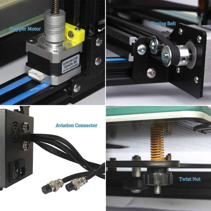
Make sure you check out our YouTube channel, and if you would like any additional details or have any questions, please leave a comment below. If you liked this article and want to read others click here.
Z-wobble in 3D printing and ways to eliminate it
Let's start with what wobble is.
This is a cyclic printing defect, which is expressed in the displacement of layers by fractions of a millimeter along the Z axis.
i.e. it is the inability of the screw, raising or lowering the Z-axis, to follow its path exactly. At certain moments, the axis mount sticks, preventing it from moving to the desired height, due to which the current layer is smeared into the previous one.
Most often, this defect is expressed as waves on the surface of the model.
For a better understanding, I sketched in paint why this happens.
So, in order to get rid of wobble on your printer, you need to determine whether the problems are really caused by it, and not by poor quality filament with an unstable bar diameter.
Print any model with flat vertical walls twice, one after the other from one file, put them side by side and compare the models with each other. Identifying the problem can be difficult if there are defects on the models caused by both wobble and bad filament.
If the wobbler could not be unambiguously distinguished among other printing defects, then you should first try replacing the plastic spool with another one, preferably from another manufacturer.
Let's move on to the mechanics. If you are absolutely sure that the problem is in the Z axis, then you should pay attention to 5 points:
1) in the coupling connecting the motor shaft and the screw that transmits rotation to the support nut, there must be a space between the shaft and the screw, as shown in the screenshot. Also, if you have a one-piece clutch, then you should replace it with a spring or split one. Since it is not designed to compensate for misalignment with a shaft
2) The support nut attachment must not be rigidly fixed. From the options for solving the problem, one can single out a simple and reliable one:
A simple solution: unscrew the screws holding the support nut, lubricate them with threadlocker and screw them back, but not completely, so that the support nut can only move freely in the XY plane
A reliable option: find on the Internet or simulate a decoupling that allows the support nut to move within certain limits, but does not fix it to the axis with screws. An example of such a decoupling is installed on Artillery printers.
3) fixing the screw at the top point in the presence of only one motor is impractical, it causes only an additional restriction of the free rotation of the screw, which can affect the uniformity of the axis movement. If 2 motors are installed and a timing belt between them, you can choose one of 2 ways: either remove the top mounts and the timing belt is completely, or try to set the entire system as coaxially as possible.
4) Check the screw, it may be deformed, in this case it is necessary to replace it with a new one.
5) Check the axles and carriages. For openbuilds, adjust the eccentrics and check the wheels for proper operation.
If the guide axles are shafts with plain bearings or rails, and there is play in them, then there is nothing to help you :D, most likely you will either have to put up with it or buy new high-quality guides.
Also, stripes on models can be caused by unstable temperature in the hotend. To fix this problem, you need to calibrate the PID controller of the heater. To do this, you need to have EEPROM activated in your firmware.
If so, then download and install the Repeater host, connect through it to the printer, go to the "management" tab, enter the command M303 C8 E0 S235
where:
M303 - team code in marlin,
C8 - number of attempts to find the correct coefficients
E0 - extruder heater code
S235 - target temperature
After the end of the auto-calibration process, 3 lines with coefficients will appear in the bottom of the terminal.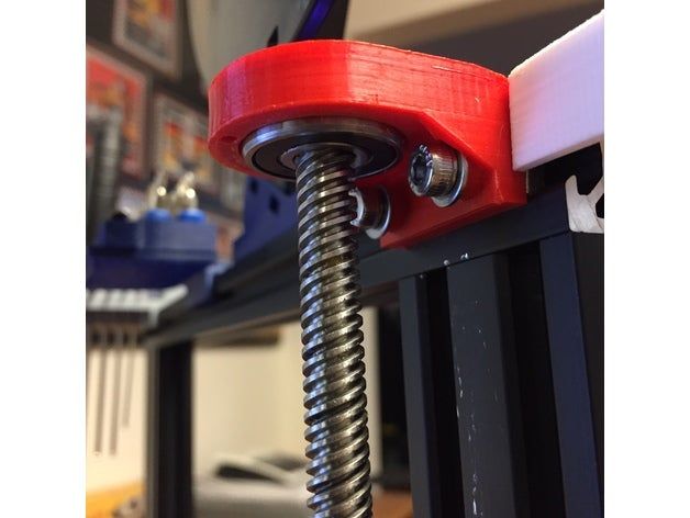
at the top of the program, click on "configuration" → "EEPROM config"
In the window that appears, look for the 3 necessary lines "PID" and write the values from the terminal into them. Then we save everything and turn off.
It should be noted that the dependence of the temperature on the thermistor on the output value going to the board is not linear, but obeys an exponential law. Because of this, the temperature measurement accuracy of the sensor at 200° and 260° will differ quite a lot. If you have a regular Chinese NTC 3950 sensor, it is likely that the dependency table in the firmware will differ from reality, which will not allow you to set an adequate temperature above 210 °, and, accordingly, calibrate it.
https://3dtoday.ru/blogs/3diy/the-thermistor-setting-in-the-firmware/
3d printer defects: errors, main problems
Causes of Defects in 3D Printing and How to Fix Them
Buying a 3D printer is only half the battle. A beginner printer has a lot to go through. First, he will learn how to set up the device, calibrate the print head, set the necessary parameters, and test different types of filaments. But that's not all. The most unpleasant thing that can appear during operation is printing defects. And they need to be eliminated.
- What are 3D printing defects?
- Classification of defects
What are 3D printing defects?
After the printing process is completed, various defects can be found on the finished model. Most often they are associated with improper distribution of plastic. Defects appear for various reasons. But the main result is always the same - the model is damaged, you need to do the project on a new one. Printing defects cause downtime. Lost time and meters of filament.
Important! Within the framework of this article, defects that occur on FDM printers will be described. These are models of printing devices operating on the technology of hot deposition of plastic.
Sometimes mistakes can be seen right from the start. For example, when printing the first layer of a model. In these and other cases, it is necessary to prevent the defect in time. However, the press all the same should be stopped. But this way you can save material and time. This article will discuss the most common defects, as well as ways to eliminate them. At the end of the article, a comparative classification of faults will be given.
Layer displacement
The second name of this defect is skew. There are several options for the development of events at once. The skew can be slightly noticeable, with a slight deviation along the Z axis. The second option is a strong offset, the model is printed in pieces. In all these cases, the reason lies in the mechanical part of the printer.
Solutions:
- Check tension belts. They should be clearly in the grooves. It is not allowed to fray or stretch the belt. Sometimes it is easier to replace the entire set of belts with a new one.

- Sometimes small misalignments are caused by an incorrectly set pulley. Make a mark with a black marker before printing, after the end of the process, check the result. Calculate the difference. Tighten the problem area if necessary.
- The printer's Y and X axes are not properly aligned. They are not perpendicular to each other. They need to be set at 90°.
Attention! In rare cases, the problem is electrical. This option must be disassembled separately, armed with a multimeter.
The first layer does not stick
The initial layer acts as a foundation. If it "floats", then the whole model will get the wrong geometry. The second and subsequent layers may slightly shift the entire workpiece. The most unpleasant thing is that this defect can be found at the very end of the print.
Solution methods:
- Platform calibration.
 If the print bed is skewed, there is a good chance that the first layer will not stick. It is best to check platform calibration before starting printing. Many 3D printing programs help to go through this setting in a semi-automatic mode.
 - Wrong print nozzle height. Another point worth considering. Most often, the extruder height setting is set through the printer parameters: Edit Process Settings → G-Code. They are located in the main menu of the device.
- The first layer was printed too quickly. The plastic just didn't cure. This setting must be found in the menu of the printing device. Approximate location: Settings → First Layer Speed. It is worth setting the print speed of the first layer 50% lower than the rest.
- Plastic cooling temperature. This option can be found on printers with a cold platform. The filament hits a cold surface, quickly hardens and rebounds. Here you need to experiment with the settings for the melting temperature of the filament or initially take a printer with a heated surface.

Important! Poor adhesion can be caused by covering material placed over the platform. Different glue, tape, adhesive tape - all this can repel plastic.
Pimples on the model
This also includes such defects as “snot”, swells, sagging. All these faults are of approximately the same nature. They are related to the operation of the extruder. As it moves, it should stop, then start working again. Not all devices can lay even layers without defects. This is how the irregularities described above appear.
Solving methods:
- Retract and coast setting. The first parameter is responsible for starting the extruder. In this case, you need to configure the retraction through the device menu: Edit Process Settings → Extruders. Here you need to find the parameter Extra Restart Distance. Try reducing the fill length.
 When unevenness occurs when the nozzle stops, you need to tighten the roll-on stroke (roll-up movement). This setting is referred to as Coasting. It is in the same section where the retraction is set.
 - It is better to avoid retraction and coasting altogether. That is, the filament must be flush with the edge of the nozzle. This parameter is especially critical for Bowden printheads. Another option is to set up retraction. You need to find the Advanced tab. It contains the Ooze Control Behavior setting. This option controls filament leakage and retraction start time.
If minor defects are still present, it is worth pointing out the entry points to the printer. This setting is found in the Edit Process Settings menu on the Layer tab. For example, you can leave small flaws inside the shape, starting printing from the inner layers.
3D printer won't print
This is one of the scariest things for a beginner 3D maker. The device appears to be broken. However, in most cases this is not the case. The printer turned on, but did not start to push through the plastic? There are four reasons for this.
Solutions:
- Plastic does not come out of the extruder due to leakage. This can often be seen in some cheap Chinese models. The filament is preheated in the extruder, it can seep through the hot end. The same effect can be observed after the end of the work. In this case, printing starts 3–4 seconds after the start. Automatic broken geometry of the first layer. To avoid this defect, experienced printers make the so-called skirt. This is a thin circle of filament around the future model. It is printed to bring the printer to life and fill the nozzle with plastic.
- The extruder is too close to the platform. The plastic just gets stuck inside the nozzle. The situation continues on the second layer. Only by the 3rd or 4th layer does the plastic begin to come out. The solution is to adjust the Z-axis height through the G-Code command.
- Sometimes the filament is simply chewed off by the drive gear. This is the part that pushes the thread forward. If a small amount of filament shavings is visible near the printer, it is likely that the gear has worn off the filament. You need to calibrate this node.
- Clogged extruder. There may be several reasons: ordinary dirt or rubbish, plastic coked inside the extruder, poor cooling of the filament. Mechanical cleaning of the nozzle with special needles or drills will help. They are sold in specialized stores.
Important! Just do not need to clean the nozzle with a screwdriver or other improvised tools. You can completely ruin the extruder.
Printing in the air
Various users are experiencing this problem. The reasons for printing by air are related to setting new plastic settings in the slicer. Sometimes a defect appears due to incorrect setting of the Z axis.
All solutions come down to the fact that the user needs to carefully study the G-code of the printer. Sometimes the reason lies in the lowered Z-axis height settings. You can also see the print step here, perhaps it exceeds the required parameter. In the slicer, you need to check the plastic installation parameters. View the heating temperature of the nozzle and platform. All settings must be checked manually. When importing a profile, the left parameters can be picked up.
Prints in reverse: how to fix
A rare defect that is not always visible at the start of printing. That is, the model comes out normal, but mirrored. Such malfunctions are often found in Chinese kits or noname devices. There are two solutions. One is simple, the other is more difficult.
Methods of solution:
- It is necessary to invert one of the axes: X or Y - it does not matter. But only one. This can be done by flipping the contacts on the power board or on the motor itself.
- Invert axis via device firmware. This method is suitable for advanced users who are familiar with programming skills.

In any case, it's better to first check all the settings in the slicer again, and only then go into the electronics of the device.
Layers skipped
The finished model shows that one or more layers have been skipped. This is eloquently evidenced by the gaps in the finished model. In rare cases, this defect is associated with insufficient extrusion. Perhaps there are problems with the capture and supply of the filament. Sometimes the reason lies in the wedging of the Z axis.
Solution methods:
- Check the mechanical part of the printer. If gaps began to appear frequently, you need to arrange an unscheduled maintenance of the device. Examine all shafts. Check that they are level and not misaligned. Power off the printer, try moving the head with your fingers. If resistance is felt, then one of the shafts is not installed correctly.
- Bearing wear. This element may simply wear out. You can see that the printer vibrates slightly.
 There is an unusual sound when printing. Diagnose a breakdown in the same way as the shaft. Turn off the power and move the extruder with your hands to find the problem part.
Attention! Remember to maintain your printer regularly. Lubricate the shafts with special oil. For example, for sewing machines. Before lubricating, clean the moving parts from dirt and plastic residues. Just don't overdo the oil. A large amount of lubricant can lead to the opposite effect.
Doesn't print in the center of the bed
Some users are having trouble printing on one side of the bed instead of the center of the bed. At the same time, in the slicer, the model is clearly in the center. There may be several solutions here.
Solutions:
- Slicer settings are down or incorrectly set. It is necessary to change the characteristics of the kinematics. Set the Delta robot parameter instead of the Cartesian robot. You also need to set the size of the table, equal to the square inscribed in the specified print area.
 In this case, set the Origin Offset parameter to half the side of the square.
 - Try to adjust the position of the X-axis limit switch. In some cases, it is moved a little to the right.
What are the problems with the 3D printer test cube?
This figure is used to check the print quality. Naturally, during the test, she can clearly demonstrate where there are problems. It can be completely different defects. Most often, the test shows bulges and dents on the model.
These defects are caused by overheating and shrinkage. To find out for sure the cause and eliminate these factors, you need to print four cubes in different angles. For some ABS plastics, you need to reduce the temperature, as well as turn on the blower by 5-10%.
3D printing echo
This problem can be described as thin stripes that form when printing layer by layer. That is, the final model does not have a formed and even surface. There is waviness (echo) on the edges. This defect is also called ringing on the walls. Typically, two factors are the cause: print speed and vibration.
Solutions:
- Reduce vibration. Make sure the printer is on a level and stable surface. Assess the condition of the bearings. Replace them if necessary.
- Inspect the shafts. Clean them of dirt and dust, lubricate with oil.
- Reduce the print speed through the printer settings.
Try changing the typing speed first, then check the mechanics.
Interesting! Even a single loose bolt can cause strong vibrations. Check all fasteners. Pull the bolts.
Salmon leather
This defect is somewhat similar to the previous one. Only there are no obvious waves or ripples. The defect manifests itself in the form of a pattern. It is similar to the representation of heights on topographic maps or the structure of salmon skin that is drawn on the walls of the model.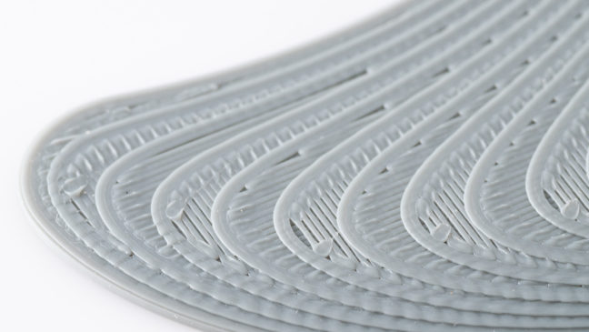 In English resources it is called salmon skin. The defect appears due to two reasons: vibrations and incorrect characteristics of the current coming to the motors.
Solutions:
- Remove any vibrations that may occur in the device. Tighten the bolts and check the frame geometry. You can also slightly reduce the print speed.
- Installation of a special impulse reducer (TL-Smoother) in the circuit between the driver and the axle motor. This solution balances the current indicators. The edges are more even.
Salmon skin defect is common on DRV8825 stepper motor drivers.
Ripple
In this case, we are talking about the partial impact of waves on some parts of the model. The ripples are often of the same nature as the echo. It is also tied to vibrations and the speed of the extruder. However, unlike waves, ripples are especially pronounced at sharp corners, when the nozzle abruptly changes direction.
Methods of solution:
- Reduce the print speed.
 You need to find the Edit Process Settings menu in the printer settings, and then open the Other tab. Change two settings: Default Printing Speed and X/Y Axis Movement Speed. The first is responsible for the speed of all movements of the nozzle, the second - the speed in the absence of plastic supply. Sometimes the reason lies in the factory firmware. It initially indicates increased extruder acceleration.
 - We remove vibrations. Check the geometry of the device, stretch all the bolts, assess the condition of the shafts and bearings. Lubricate the device if necessary.
We recommend checking the print speed settings first.
Poor filling
If the figure is not filled enough, it means that it will not receive sufficient strength. The model may simply break or crack. Usually the causes of poor coverage lie in the slicer settings or print speed settings.
Solutions:
- Try changing the fill pattern. It is indicated by the Internal Fill Pattern parameter. There are presets in the settings with complicated filling options that give more strength to the finished model: Grid, Triangular and Solid Honeycomb. The printing time will increase, but the strength will also increase.
- Reduce print speed. The fast movement of the print head results in less infill. You need to tweak this parameter through the settings of the device itself or through the slicer parameters.
- Change extrusion width parameter. Some 3D printing programs allow you to set different infill values for individual elements. For example, for the outer layers, set the size to 0.4 mm, for the inner layers - 0.8 mm. These settings can be viewed in the menu Edit Process Settings → Infill. In it you need to find the parameter Infill Extrusion Width. It is shown as a percentage. The higher the number, the thicker the layer.
Attention! When setting the Infill Extrusion Width parameter, make sure that the set value (in percent) is supported by the printing program (slicer).

Plastic is leaking from the extruder threads
This fault can be attributed to local printer failures, although they can create a number of defects in the form of "snot" on the model. Plastic oozes through various slots, flows down the extruder thread, exits the opening of the heating element. There may be several options for solving the problem.
Solutions:
- Check all screw connections. Sometimes a caked piece of plastic gets stuck between them. It creates a gap, the filament flows out.
- Clean and polish the surfaces of the thermal barrier tube and nozzle. Installing a fluoroplastic washer or winding a fum tape can also help.
- Reinforced cold drawing of threaded connections.
Attention! Sometimes the reason lies in the factory marriage. Nothing can be done here. Just completely change the extruder.
Plastic does not come out of the nozzle
For some reason, the printer stopped feeding filament. The device continues to make noise with the engines, but the plastic does not come out of the nozzle. There may be several reasons and solutions for this.
Solution methods:
- The plastic is out. For some printers, the filament spool is covered with a casing. Therefore, it is impossible to immediately understand that the thread is over. Check for material in the spool.
- The thread has broken. There was a gap between the hot end and the extruder. A common cause is with Bowden printheads. Perhaps the problem is with the filament itself. You need to try other material.
- Low plastic melting point set. The thick filament cannot pass through the narrow nozzle opening. Recommended temperature parameters for different types of plastic: PLA - heating t 180 °C, table heating t 60–80 °C; ABS - heating t 240 °C, table heating t 110 °C.
Interesting! Sometimes a clogged nozzle is the cause of interrupted printing.
This can happen even during work.
Model delamination
Visually, this defect looks like an accordion. In some places, the layers move away from each other. At the same time, it is clear that this is not a pass, but the absence of sticking of plastic. Layer separation occurs due to incorrect setting of the filament thickness or its melting temperature.
Solving methods:
- Reduce layer thickness (height). Here you need to follow the rule: the maximum layer thickness should be no more than 80% of the nozzle diameter. Otherwise, the layers will not stick to each other.
- Raise the melting point of plastic. If the height parameter is in order, then you need to look at the temperature settings. For example, the optimum melting temperature of ABS plastic is 220–240 °C, but some users set it to only 190 °C. You can increase the melting temperature in the slicer settings: Edit Process Settings → Temperature.
If standard temperatures are not suitable, try raising the setting by 10 °C.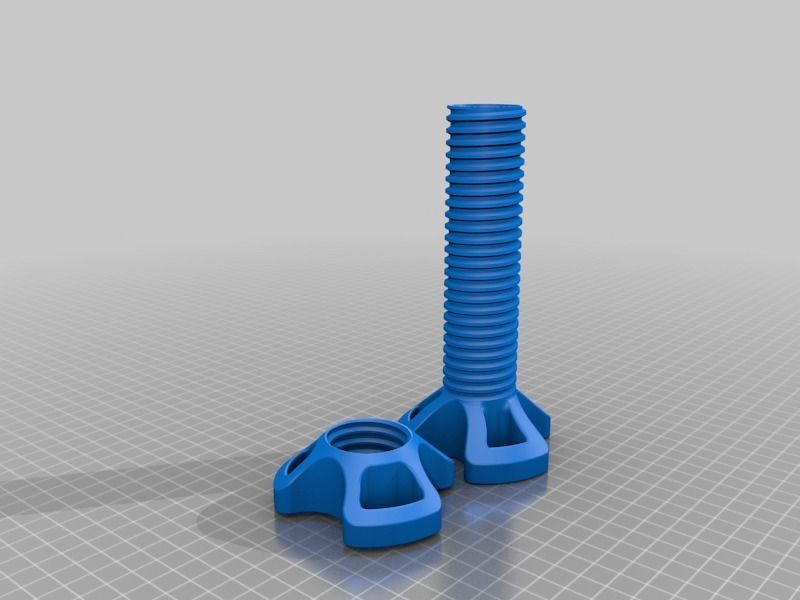 See if the adhesion of the layers improves or not.
3D printer extruder does not heat up
At the same time, the device shows 100% heating power, the set temperature is on the display, but the extruder is cold. In most cases, the cause lies in a break in the wires or in the heating element itself. Ring all circuit elements after the controller. To cut off problems on the heating element, apply 12 V to it. It should start to heat up.
Attention! Newer printers may encounter a factory extruder defect. This element needs to be changed. There is no point in repairing the item.
Plastic falls in waves
Another name for this defect is “elephant foot”. In this case, the upper layers of the model are pushing against the lower parts, causing a wave effect. It sort of descends from top to bottom, forming a thick layer at the base of the model. This problem is especially common on models of printers with a heated bed.
Solution methods:
- Find the optimum temperature between heating the table and blowing the model. Lower the heating temperature in steps of 5 °C. It is important to find a balance here, when the lower layers have already gained strength, but still retain adhesive properties for the following layers.
- Calibrate the table. Try applying the default settings. If the problem persists, slightly change the Z-axis height settings. Calibrate the new settings on the test cube. This is the base shape that clearly shows how the layers are laid down.
- Chamfer the base. The option is suitable for homemade devices. You need to start with a bevel of 5 mm and 45 °, after which you can make small adjustments.
Wall gaps
Such defects can be found when printing rather thin walls in the model. For example, when the extruder nozzle prints strips up to 0.4 mm thick, and the user needs to make a 1 mm edge. In such places, cracks may appear at the joints of the two layers. Typically, the defect is eliminated through the adjustment of the slicer.
Solution methods:
- We need to find the setting that is responsible for the wall thickness. Usually they are in the menu: Edit Process Settings → Advanced. Here you need to find the Gap Fil parameter. He is just responsible for overlapping areas and filling the gaps between thin walls. Check the box next to Allow gap fill when necessary. There is also an alternative. Go to the Infill tab and tweak the Outline Overlap parameter.
- Simply adjust the extrusion width. Increase the parameter value if possible. The strip width can be set on the Extruders tab via the Edit Process Settings menu.
Try and experiment to get the best fit.
Web
A special case of filament leakage, when sloppy plastic threads remain between the parts. This happens for the same reasons as influxes. The solution methods are exactly the same:
- Changing the speed and distance of thread retraction.
 Full instructions are listed above.
 - Lower print temperature. Try tweaking this setting to reduce the fluidity of the plastic. Here you need to be careful. Excessive decrease in temperature can lead to a delamination defect.
- A separate solution is to set a parameter in the slicer that launches the print head in a long and winding path over empty space. The web falls near the model without sticking to its walls. No bridge is formed between the layers. To enable this option, go to the advanced settings of the slicer (Advanced). Check the box next to the Avoid crossing outline for travel movement option.
Interesting! Some 3D makers do not consider a web defect as something serious. They simply cut off the excess filament with a knife after the print is finished.
Extruder does not feed plastic
This problem is in the filament feed mechanism. Or the nozzle is too close to the table.
Solution methods:
- Check the plastic filament.
 It may have burrs on it. The feed gear has slipped. Check the condition of the thread, you may need to tweak the gear settings a little. Or change the plastic.
 - Calibrate the table position. Raise the Z-axis a little.
Sometimes the extruder refuses to feed plastic due to a clogged nozzle. It needs to be cleaned up.
Classification of defects
Almost all defects are one way or another related to two reasons: a malfunction of the mechanical part of the printer or incorrect software settings. Based on these parameters, it is possible to make a classification based on the most common problems in printing:
- Deterioration of nodes and the lack of a normal fastener feed. This parameter affects vibrations, nozzle movement trajectories.
- Poor extruder maintenance. The print head needs to be cleaned from time to time, to remove the sintered filament.
- Inaccurate (wrong) calibration of the platen and nozzle height. Another common mistake that causes a lot of print defects.

- Problems with printer settings. Most often solved through manual setting of parameters or adjustment of the G-code.
- Lost settings in the slicer. This includes: changed parameters, errors or inaccuracies in the firmware.
- Poor quality filament. The problem may lie in the quality of the plastic. It is necessary to monitor its condition, quantity. If necessary, try to replace the manufacturer, or even switch to another type of filament.
- Electrical problems. To find such a malfunction, you need to arm yourself with a multimeter and ring all the circuits after the controller.
- Factory defect. The problem is solved by replacing a low-quality part.
These are the main printer malfunctions that in one way or another affect its operation, which leads to printing defects. The printer may have several problems at once. They will lead to the appearance of a group of defects. You need to be able to recognize the first signs of breakdown in time and eliminate them.