What is slicing in 3d printing
What is the role of Slicing in 3D printing?
Humans are gifted with senses that help make decisions and perform activities. Like humans, machines have methods of processing information. Machines also use tools at their disposal to translate a set of instructions into formidable actions. That is how all machines work and 3D printing is no different.
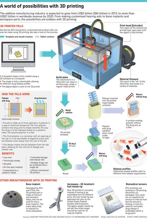
“3D printing, also called additive manufacturing, turns digital files into physical objects by building them up layer-by-layer. Imagine a cucumber sliced into paper-thin slivers by a mandolin and then put back together.”
Whenever we talk about 3D printing, we hear certain terms repetitively. “Slicing” is one such word that can not be ignored. It is the intermediate and most important step in the process of 3D printing. In this article, we will try to understand the role slicing plays in 3D printing.
Here is a list of sub-topics that will be part of this discourse :
- What is Slicing?
- Components of a Slicing Software
- Features of a Slicing Software
- FDM vs SLA Slicer
- The ultimate list of Slicer Softwares
1.
The act of converting a 3D model into a set of instructions for the 3D printers is called Slicing. Quite literally, it ‘slices’ the 3D model into thin layers, and further determine how each layer should be printed (the tool path) to get minimum time, best strength, etc.
A slicer software takes a 3D CAD model which is generally an STL format file and converts it into a g-code that gives commands to the printer. Following are the three major types of settings that can be controlled in a slicer software —
- Print Settings: layer heights, shells, infill per cent, and speed
- Filament Settings: filament diameter, extrusion multiplier, the temperature of the extruder, and print bed.
- Printer settings: nozzle diameter, print bed shape (L x W), and Z offset.
In the next few sections, we will delve into some of these Slicer settings that will directly impact the 3D print quality of the models.
2. Components of a Slicing Software
It is important to understand how data flows in the 3D printing process.
Data flow in a 3D printing processLike every software, we can divide it into two components — front-end & backend, OR — GUI and Logic. The front-end consists of the parts that the user directly interacts with. This is where the user visualizes the CAD, as well as the gCode and tool path. The back-end components contain algorithms or instructions for the code execution. Let us look at the components of the Slicer software.
Parts of a slicer softwareFront End
GUI is the graphic user interface. It has all the tools that help the user interact with the 3D model. As you can see in the picture below, the graphic user interface of a free web-based software named Buildbee. It enables the user to move, scale, rotate, and change the settings for the 3D model.
Buildbee’s user interface (Web-based slicer software)The main function of the slicing software is to work with the STL format file. It stores the visual image of the 3D model. It stands for “STeroLithography,” sometimes also called — Standard Triangle Language/Standard Tessellation Language. It has information regarding the surface geometry of the model. In a nutshell, it encodes the model description for the slicer to pick up and display the visuals. The word “tessellation” is associated with STL files as it breaks down the complex 3D structures into 2D models. In the image below, we see that a sphere can be represented using a bunch of small squares or triangles.
Certain tessellation rules help in giving a good 3D print quality.
- Vertex to vertex rule: every triangle must share 2 vertices of its adjacent triangle.
- Orientation rule: The direction of the normal vector has to point outwards and the vertices are listed in anti-clockwise order while viewing the object.

- All positive octant rule: The coordinates of the model must be all positive.
Things to keep in mind while exporting the STL —
- Angle control: Gaps between the triangles prevent angle deviation and improve print resolution.
- Chordal deviation: A parameter called the chord height (maximum distance between the surface of the design and the STL diagram) needs to be maintained. The chord tolerance is set between 0.01 to 0.001 mm as a standard.
- Binary/ASCII: STL files can be shared in two types of encoding; Binary & ASCII. Binary files are small and ASCII files are large in size.
Back End — The logic
The back-end handles —
- Reading the STL
- Slicing STL into layers and determine the tool path to print the object, and
- Writing the gCode
The most important component of the slicing process is the gcode. Based on the user inputs, the back-end generates an optimized code to print the object. A gcode is nothing but the set of commands to execute the print action. It helps in providing instructions to the machine controller. A 3D slicer generates this gcode automatically.
A deeper understanding of the gcode can help one troubleshoot issues while 3D printing. There are two types of commands — “G” & “M” here is the basic syntax of the code:
Code Syntax for gCodeSlicing Algorithm: Understanding the G-code
Sample Algorithm to read and analyze Gcode (Source: ScienceDirect)We can convert the facets (from the stl file) into separate segments through a slicing algorithm. The algorithm looks at the gcode and extracts the information accordingly. It helps in understanding the gcode to help slice the model into smaller parts.
(1) Selecting the portion to be sliced (2) Sliced parts of the modelSo far we have looked at the components that enable the slicing of a CAD output model. It’s now time to look further into some more features that will help us print the best quality 3D objects.
3. Features of a Slicing Software
Once you retrieve the STL file from the CAD software, there are certain settings in the software that you must cater to…
OrientationAfter loading the stl file on the slicing software, we need to align the 3D model to the given space. As mentioned above, one has to follow the orientation rule.
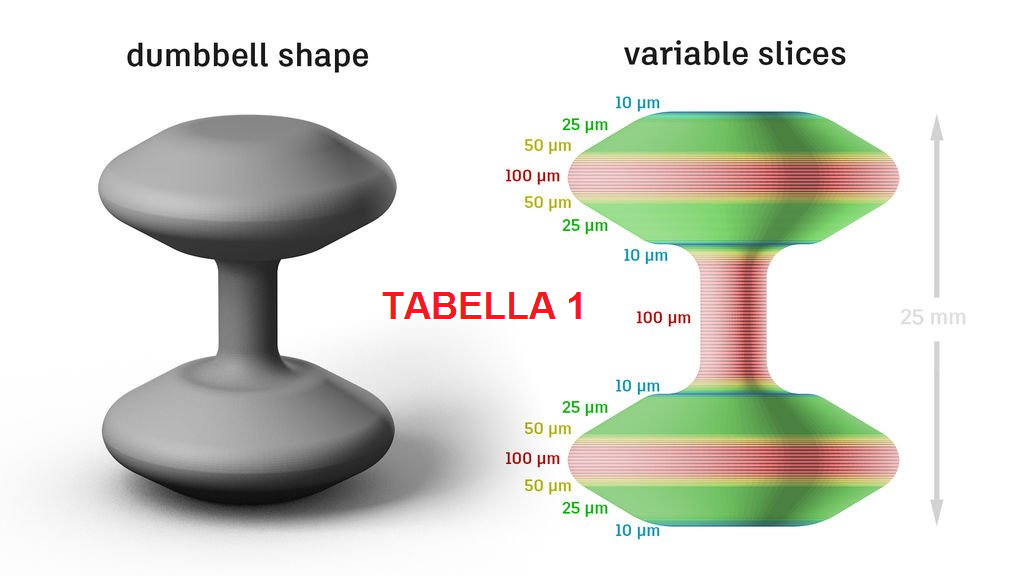
Setting the orientation in the Slicer SoftwareLayer Height (Object resolution)The resolution of a 3D object is highly dependent on its layer height. Smaller layer heights give high resolution and smooth surface. However, the overall printing time could be more.
Layer Height: Resolution of PrintsObject Shells (Shell Thickness)The outer layer that builds the wall of the object is called the object shell or perimeter. The strength of the object is dependent on the number of shells present. Higher shell count → higher strength!
Object Shells: Strength of the printsInfillDensity: Infill density is measured in % percentage. It can range from 0–100%. An object with 0% will have a hollow interior and an object with 100% density will be solid. Objects with high density will have a longer printing time. The recommended shape for the infill for optimal speed and strength is a honeycomb structure.
Types/Shapes: The design of the infill pattern can have an impact on the strength and flexibility of the 3D prints. Based on your requirements you can pick the infill type. For eg.,
- Functional prints: Cubic, octet, gyroid
- Figurine and model prints: Lines
- Standard prints: Grid or triangles
- Flexible prints: Concentric
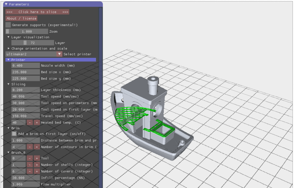
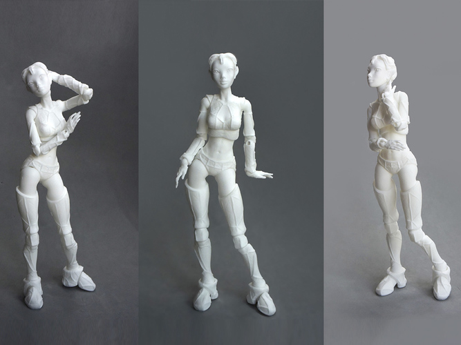
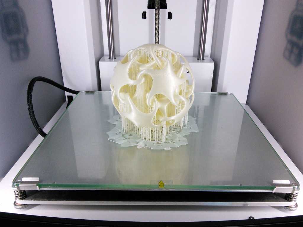
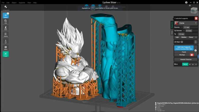
In the processes of 3D printing, one layer is printed over another existing layer.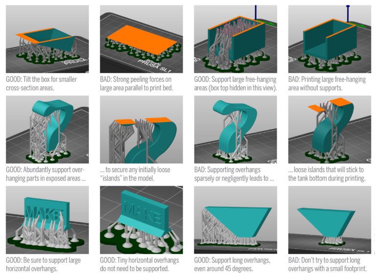 This means every layer needs an underlying layer to support it. If a model has an overhanging part, it still needs a supporting layer. This supporting layer is called the support structure. Slicer software has the ability to insert supports as in where it is needed. The support structures are easily detachable post-printing. In the picture below, the blue color component is the support structure for the given 3D model.
It is common for 3D printed objects to get stuck on their print beds (physically, not in software). To avoid this, the slicer offers some good solutions. It uses some structures that make the detachment easier.
- Skirt (as shown in fig ‘a’): It is a single outline surrounding the part without touching the actual 3D object.
- Brim (as shown in fig ‘b’): It is a layer printed along the print bed that touches the actual 3D object.
- Raft (as shown in fig ‘c’): A series of layers are printed before the model is printed. It serves as a detachable base for the 3D object.
Slicing software gives us these simple techniques to avoid any adhesion to the print bed, which is a common problem in 3D printing.
Brim and Raft Structure for a 3D printed model (Image Courtesy: 3D printer build plate adhesion by Paulo Kiefe Licensed under CC BY-SA 4.0)Print speedThe slicer software has speed settings that can be adjusted based on the geometry of your 3D model. The slicer has default settings for the speed which may be lower than what you might want. The speed can also vary depending on the type of materials you use. Typically, for PLA or ABS the recommended print speed is 40–60 mm/s. Below are the print speed parameters that need to be considered based on the shape of your model.
The print speeds are categorized into two types — print moves & non-print moves. Below is a chart to help you understand the different types of print speeds. The travel speed under non-print moves refers to the speed at which the extruder moves from the end of one extrusion to the next. This is crucial in preventing oozing.
Different types of print speedsOptimized Print PathsAn optimized printing path is crucial to 3D printing. It affects printing time, surface roughness, strength, etc. Printing paths have a direct impact on the time taken to complete a certain print. A path planning strategy can help optimize the overall printing process. This will result in a shorter fabrication time.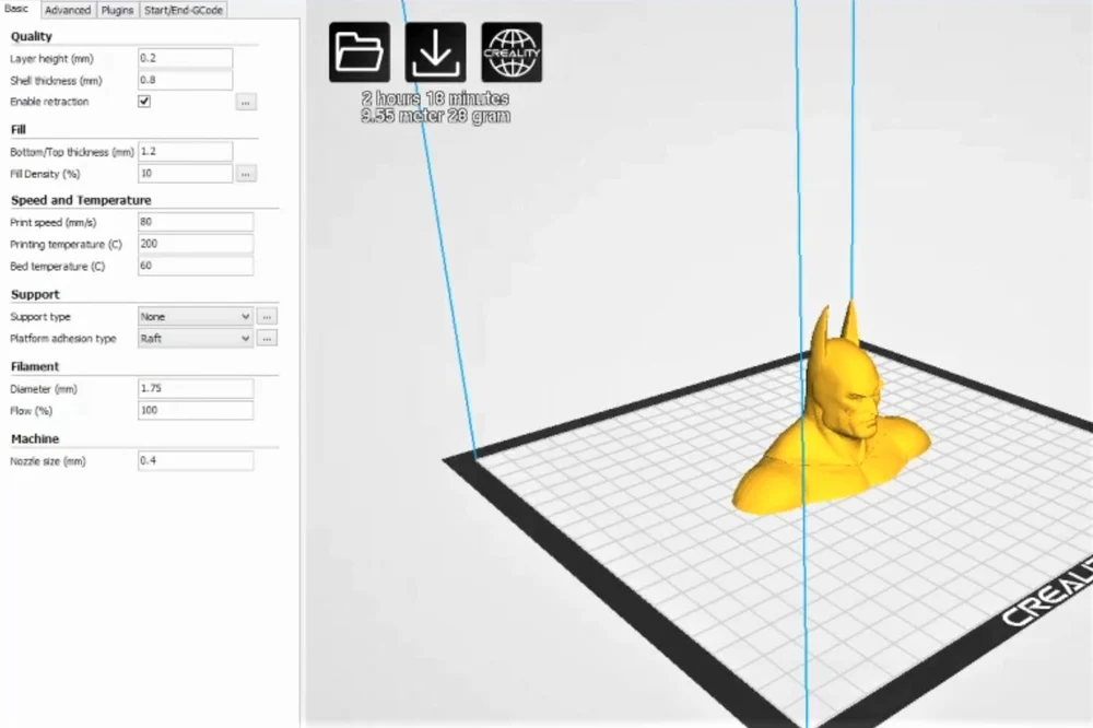 Slicer software has pre-defined print paths that one can select from. Some of the widely used paths are available in slicer softwares such as Cura, Slic3r.
One of the most important slicer settings is the temperature. It needs to be calibrated as per the print speed settings. It is important to increase the temperature if the print speed is set to a higher number. This is because, if the print speed is not matched to the temperature, it can lead to “under extrusion” due to improper melting of filaments. Also, high temperatures can lead to “over extrusion” and result in blobs or zits. It is recommended to increase the temperature between 5–10 degrees Celcius for every 5–10 mm/s rise in the print speed.
Another important factor to consider while controlling the temperature is the type of material used in the printing process. Below is a list of materials with set values of temperatures used in 3D printing.
Recently, multi-extruder 3D printers have become popular. Multi-nozzle (or multi-extruder) printers have 2 or more extruders. It is commonly used to print a 3D object with different materials. This type of design can also help reduce the waste generated in the typical single-extrusion method. The printer will have a dedicated nozzle for a given material. It is possible to dedicate one extruder to a certain region and another to a different region. The calibration of the nozzles is important in this case to avoid any mistakes. Using slicing software, it is now easy to assign different roles to each extruder.
Slicer Image of a 3D model for multi-extruder printing (Image Courtesy: multi-color 3D print byCreative Tools Licensed under CC BY-2.
 0)Extruder Settings in Slic3r (Source: Slic3r Manual)
Now that we have looked at different parameters for slicer settings, we can look at how these settings may vary for different types of printers.
FDM vs SLA Slicing
FDM and SLA are the two most common techniques in 3D printing. We have often compared these for various characteristics. Let’s look at how the slicing methods differ for each one of these
Before you read any further, don’t forget to check out our detailed coverage of FDM vs SLA printing techniques.
FDM Slicing
The print movement of the extruder or nozzle in an FDM printer is confined to the X and Y axes, while it moves in Z for changing layers. The FDM printers are dependent on the multi-axis control. This needs to be looked after to get the best printing accuracy. Temperature control settings — for heating and cooling of extruders and print beds are important for FDM printers. Some of the best slicer softwares for FDM printers, that have tested pre-defined algorithms to execute the gcode are Cura (free) and Simplify3D (paid).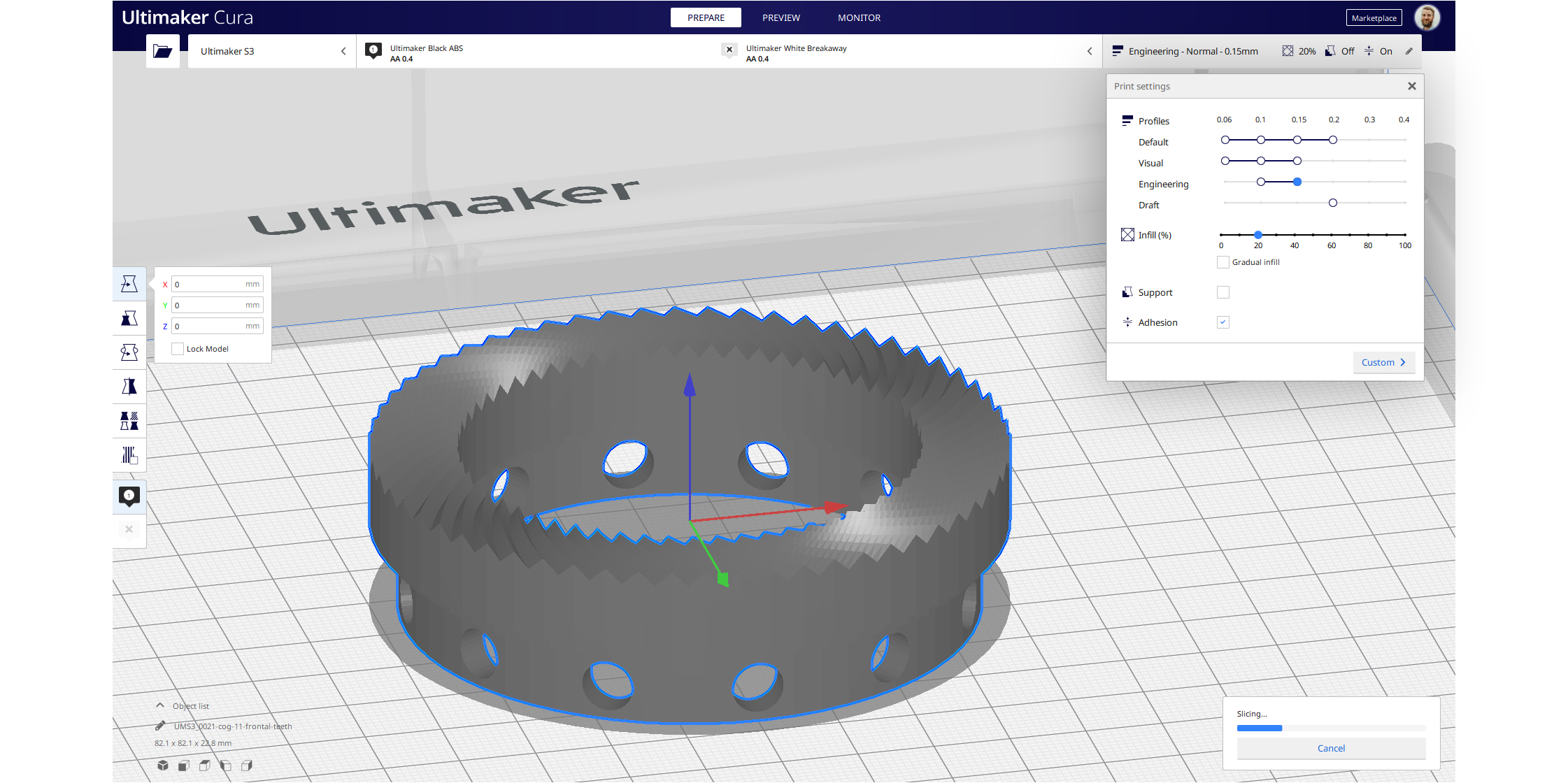
SLA Slicing
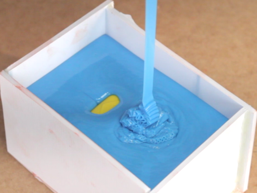
In SLA printing, the build platform moves up and down to dip into the resin tank and form layers one after the other. Therefore, the movement is along the z-axis for SLA printing. The major difference between FDM slicing and SLA slicing is that the SLA printers do not use a gCode as the output file. SLA printers have their own built-in slicing softwares. As SLA printers are devoid of extruders, the nozzle temperatures are irrelevant here. Instead, it has exposure time and lifting speeds as some of the key parameters. There are a few third-party softwares common to SLA printers— ChiTuBox and FormWare.
The Ultimate List of Slicer Softwares
— As of July 2021
- Cura (Basic — Free, Enterprise level — Paid): Latest version is Cura 4.10. The first public version 3.0 was released in September 2017 by Ultimaker. It was developed by David Braam in 2014.
- 3DPrinterOS (Paid): Latest version is 7.3.26 beta (with 2+ weeks of testing).
 According to their websites, the initial stable version 6.2.3 (with 1000 hours of testing) was launched in February 2020.
 - IdeaMaker (Free): Latest version is 4.1.1 release in April 2021. The first public version 2.6.0 was released in May 2017.
- KISSlicer (Basic — Free, Pro — Paid): Latest version is v2 alpha 2.0.6 in May 2020. The first public version KISSlicer 1.6 was released in September 2017.
- Repetier-Host (Free): Latest version is 2.2.2, released in April 2021. The first public version 0.20 was released in September 2011.
- OctoPrint (Free): Latest version is 1.5.3, released in January 2021. The first release was in 2012.
- Slic3r (Free): Latest version is 1.3.0 release in May 2018. Its first public release was in 2011
- AstroPrint (Basic version — Free, Premium version — Paid): The company has set up its cloud-based platform in 2013.
- Simplify3D (Paid): The latest version of Simplify3D is 4.4. Its first public release was in 2013
- IceSL (Free): The latest is IceSL version 2.
 4.0-beta released in June 2021. The company released its first public version in June 2016.
 - Mention our own?
Conclusion
This discussion on slicing software is important with regards to the 3D printing process. The slicing process is crucial in determining the print quality of your 3D models. Therefore, understanding various aspects of slicing can help you manoeuvre the 3D printing process with ease.
3D model slicing is the puzzle piece that completes the 3D printing process. Its role in 3D printing is definitive of the printing standards that you set for your 3D models. We tried to give you a walkthrough of the fundamentals of slicing software that can help you put some obvious doubts to rest.
Despite all the knowledge on slicing settings, 3D prints can still find you in a sticky situation. For those specific times, you can check out our article on fixing 3D print problems!
Don’t forget to share your thoughts or experiences with 3D slicing softwares in the comments below…
About Maunica Kolla
I am a former software engineer with a degree in Electronics and Communication.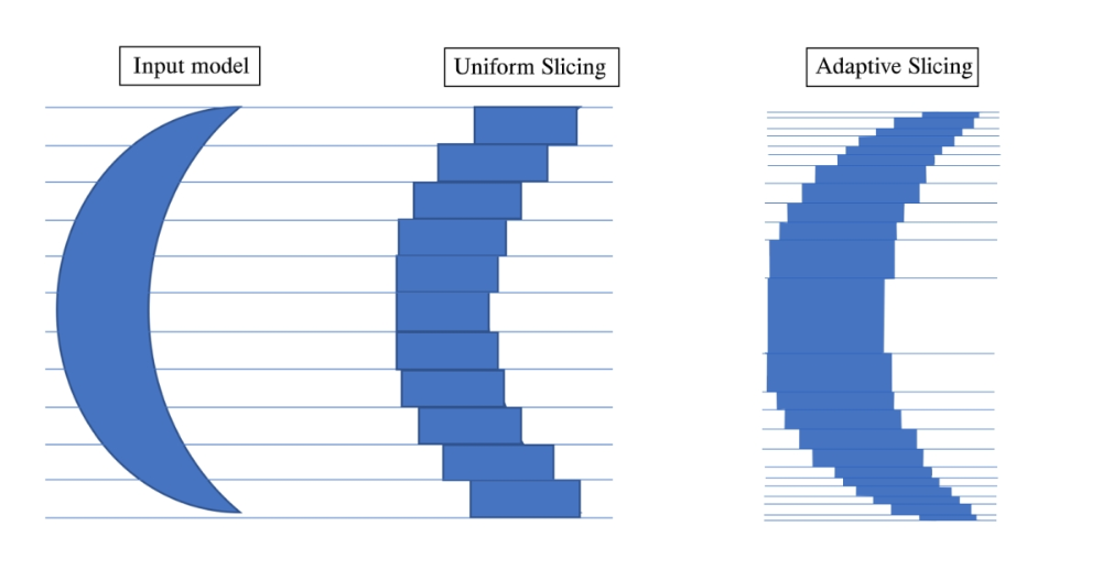 I have always been writing poems and stories since childhood. In college, I also had a chance to pursue a minor degree. English literature was my obvious pick. I took up courses related to creative writing and academic writing. This is when I began to enjoy and relish the process of writing. I love to research and learn new things every day. Ever since then I have been writing regularly.
What Is 3D Slicing and Why Is It Important?
3D slicing is the process of taking a 3D model and converting it into instructions that the printer can understand. It is an essential step in the 3D printing process, and it’s important to know how it works and how you can slice your 3D models using popular and industry-standard 3D slicers like Cura.
How 3D Slicing Works
3D printers work by reading 3D files and printing them layer by layer, usually in thin layers of about 0.1mm thick. A 3D slicer takes your 3D model and translates it into a language your 3D printer can understand, which is called a G-code.
The G-code file contains instructions for each model layer so that your 3D printer knows what to do. The file contains the instructions like how the printer should move, what speed to use, and the size of the 3D printer filament to extrude.
When creating a G-code file it is essential to ensure that the instructions are clear and accurate. Incorrect instructions can result in poorly designed parts or even damage the machine. Once you create the G-code file, there is an option to modify it if necessary.
The Important Settings in 3D Slicers
There are several basic settings found in most 3D slicers. One of them is the infill percentage. The infill is the amount of material the printer adds inside the object. A lower infill percentage means you use less material, and the design will be lighter. A higher infill percentage means you use more material, and the 3D object will be more robust.
The slicer software allows you to select the type of infill pattern you want.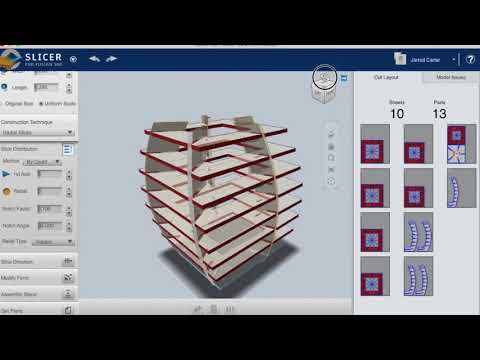 Examples of infill patterns include the honeycomb, octagon, and zigzag. Each infill pattern has advantages and disadvantages. For example, octagon patterns use less material than other patterns, and zigzag patterns are robust.
3D slicing software also allows you to add support structures to your model. 3D printing supports are essential for holding parts of the model that would otherwise collapse during printing. Printing some objects, especially those with overhangs, would be challenging without support structures.
You can also select the type of nozzle you want for your printer in the slicer. Nozzles are made of plastic, brass, or stainless steel, and they come in different sizes and materials, and the most common nozzle sizes are 0.4mm and 0.2mm.
There are many other settings that you can adjust in 3D slicing software, but these are some of the most important ones. Let's now have a look at how you can slice your models using Cura, the popular 3D slicer, and SelfCAD's in-built slicer.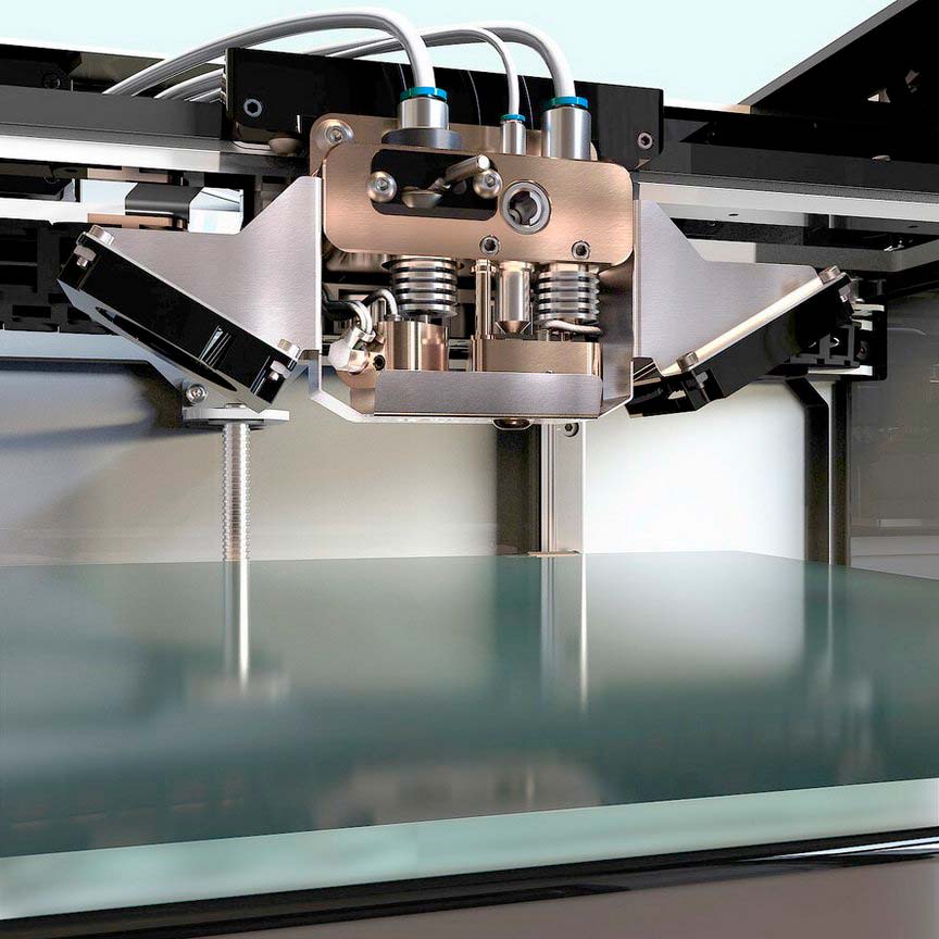
Steps to Slice a Model Using Cura
Once you have downloaded and installed Cura, launch it and go to File > Open File(s), and this will bring up a window where you can locate and select the file containing your 3D model. Then click Open in the bottom-right corner of the window. Your model should now appear in the Cura workspace.
To customize your slicing settings, go to Fine > Custom. As shown below, a new window will open where you can adjust various parameters such as walls, infill density, and supports settings.
Once you are happy with the settings, click Slice at the bottom of the window, and the slicing process will start. Once completed, there is an option to preview your design and see how it will be 3D printed, as shown below.
When you are done, you can click Save to Disk, and you’ll see several options to save your design. We recommend saving either as a G-code, OBJ, or STL file, as these are the formats that a 3D printer can read.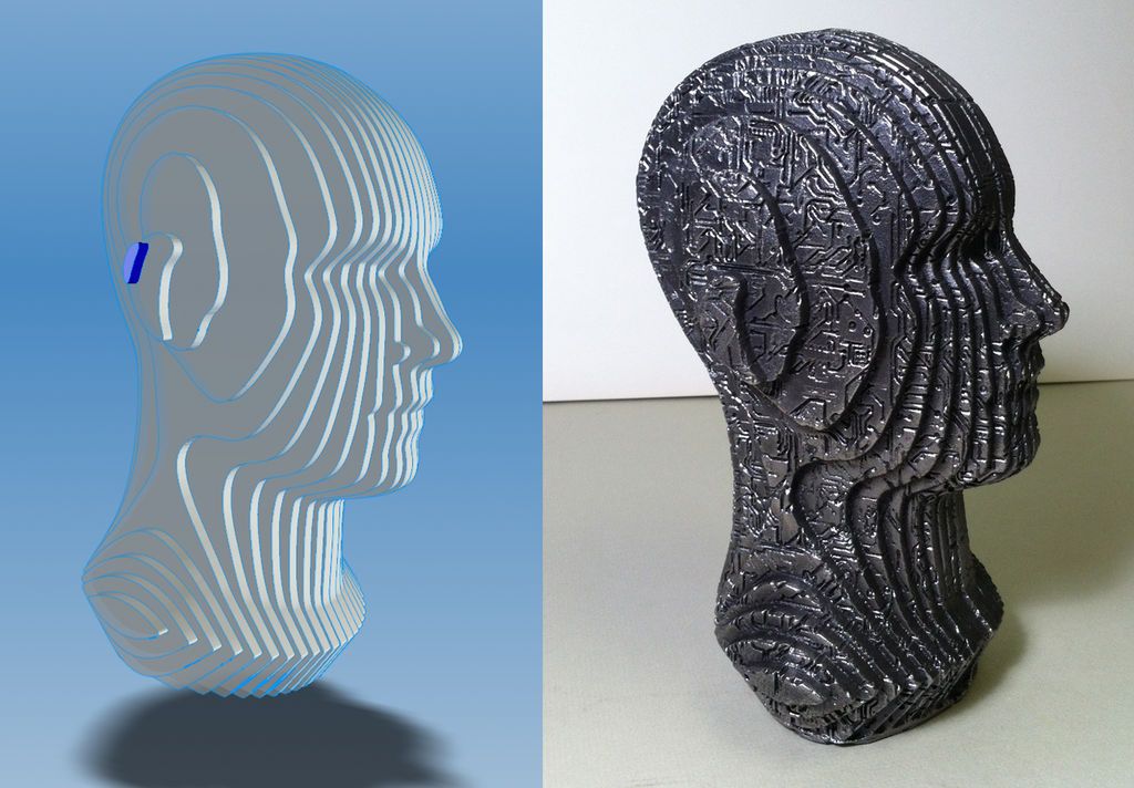
Steps to Slice a 3D Model Using SelfCAD
SelfCAD is a 3D modeling software that comes with an in-built STL slicer. Once you have designed your 3D model and are ready to slice, you can access the 3D slicer by selecting the 3D Print tool in the menu bar's top-right section.
Once you click the 3D Print option, you will see a new window where you'll select your 3D printer and then have access to several settings configured to slice your design. The first setting is Quality, where you can choose from six options to set the quality of your 3D print.
Another important setting is the Infill percentage, which determines how much of the internal volume of a 3D model should be filled in with plastic when slicing. For instance, you can lower this percentage if you want to save material and weight. On the other hand, if you want to maximize strength and durability, you can increase it.
The other main settings are Support and Material. The Support option allows you to choose if your 3D model should have support structures, while the Material option enables you to select the material with which you want your design to be 3D printed.
Finally, we have the Settings option where you can find more settings. One of them is the Layer Height which allows you to specify how thick each layer should be when slicing your 3D model. This will determine how much detail is captured in each layer and impact the overall print time depending on how small/large it is set.
Another setting here is Shell, where you can set how thick the outer walls of a 3D model should be. This impacts the overall strength of the structure and its ability to withstand different types of stress or pressure. Depending on what kind of object you are printing, this setting could also impact print time and material cost efficiency.
Once you configure all the settings, you can select Slice, and the software will generate the G-code file you can send to your 3D printer. Just like in Cura, you can also preview your design and know the amount of material required and the printing time.
Benefits of 3D Slicing
- Easy customization: You can specify the thickness of the walls, the 3D printing speed, and even the fill density of the object. Using slicing software like Cura, you can also split an object into several parts.
- Reduced waste and cost savings: You can reduce the cost significantly since you can specify the thickness of your design and other settings involving the usage of materials and the model's overall design.
- Know the material size to be used: During 3D slicing, you can see the material size your project will require, which helps you plan.
- Know the time it will take to 3D print your model: In addition to seeing the size of the material that your project will require, you will discover the amount of time it will take to complete it.
3D printing is a fantastic technology that allows you to create 3D objects from a digital file. However, 3D printers cannot understand the 3D model as it is: you must first convert it into a format they understand, and this is the work of a 3D slicer. There are various slicing programs out there that can do this for you, but it's essential to choose one that is compatible with your particular printer. We hope that the two slicers described here can help you get started easily.
REC Wiki » Taper Slicing as a More Efficient Method for 3D Printing Hanging Structures
Standard slicers and FDM 3D printers slice 3D models horizontally, often requiring heavy use of support structures. Is it possible to do without supports and reduce material consumption? You can if you use the conical threading method.
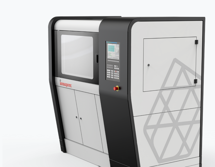
In recent years, several non-planar cutting methods have emerged, although none of them has yet been widely adopted. One of the simplest and most interesting is the so-called conical threading. Such a scheme was implemented by scientists from the Zurich University of Applied Sciences (ZHAW), who assembled a four-axis 3D printer based on the Prusa i3. By mounting the hot end at a 45-degree angle on the rotating head, this system is able to print parts with large projections without building support structures. What is most interesting, the same approach can be used on conventional, unmodified FDM 3D printers with vertical hot ends and get very similar results.
Conventional and bevel cutting and stacking
Conventional 3D printers can print inclined surfaces, but only to a certain extent. At too large angles of inclination, the plastic will be extruded not so much on the already formed layers, but into the air, which means it will slide and sag. Hence the need to build supports that, after 3D printing, are separated from the model and turn into garbage. With conical cutting, the layers are slightly tilted so that when 3D printing hinged elements, only the edges of the layer line up “in the air”, and even then they maintain contact with neighboring perimeters. All this allows you to print parts of much more complex shapes without support structures.
One of the key considerations when using this method on conventional FDM 3D printers is the nozzle length. The nozzle must be long enough (that is, high) so that the rest of the head structure does not touch the laid material, because now the printer prints not strictly horizontal, but inclined layers. A lot here depends on the design of the head: in most cases, the fans and blower pipes leave a very small gap, which seriously limits the slope of the layers. The longer the nozzle, the higher the clearance and the possible angles of inclination of the layers. For example, in the Prusa Mini 3D printer, the cooling system is located quite high, which allows you to tilt the layers at angles of more than twenty degrees. On the other hand, when using the popular Ender-3 3D printers or their many imitations, the easiest solution is to install a nozzle with a long tip. At the same time, it is highly desirable to dismantle the calibration sensors from the head, since they are likely to interfere.
Artillery Hornet 3D printer with extended Airbrush nozzle
The problem is that the higher the cooling systems are, the worse the airflow will be. In some cases, depending on the material, this moment will have to be compensated by a reduction in the paving speed.
The main question is in which slicer to generate machine code? Fortunately, you can use almost any program, but you have to cheat a little. Simply checking the box and switching to the conical cutting mode will not work, since there is no such option yet in any popular slicer, however, any slicer can be fooled and forced to generate the desired G-code using a couple of scripts written in Python. The first script deforms the 3D model in the STL file into the shape of an inverse cone, moving the points of the polygon mesh up by a distance depending on the distance of the point from the central axis. The resulting 3D model is cut in almost any slicer - Cura, PrusaSlicer, Simplify3D or some other. Then the second script converts the machine code back so that the 3D printer prints an undistorted, original model, but with an inclined stacking instead of a horizontal one.
The necessary scripts were developed by the Swiss researchers from ZHAW mentioned above, then modified by Stefan Hermann, the author of the CNC Kitchen Youtube channel, for conventional FDM 3D printers and made available to the public. At the same time, Stefan shared a good example. This example uses SuperSlicer, a variant of PrusaSlicer with some additional and very useful features, such as the ability to export G-code with empty layers.
The STL file is loaded into the slicer with a slightly modified 3D printer profile, where the origin is in the center of the table. The model is placed on the table so that the global Z axis is aligned with the axis of the future cone, and saved.
Then the first script comes into play: you need to specify the angle of inclination in it, after which the script transforms the part into a pre-deformed, “conical” model.
The part is then sliced in the slicer as usual and saved as a G-code.
At the final stage, the name of the file with the machine code is inserted into the second script, which converts the code for building the deformed model into the code for building the original part. The whole process takes just a couple of minutes.
It must be understood that this method is not ideal: not only does it add work, albeit a little, but in some cases it can be less practical than conventional horizontal 3D printing. Please note that the illustrations above show examples with external tabs. If tapered threading is applied to 3D models with internal hinged structures, an even larger volume of support structures will be required than after horizontal slicing. Keep this in mind and choose the most appropriate method according to the circumstances.
10 rules for preparing a model for 3D printing But, if we talk about FDM 3D printers, then not every model can be printed, and almost every model (not prepared for 3D printing) has to be prepared, and for this it is necessary to imagine how this 3D printing goes.

First, a couple of definitions:
Slicer is a program for converting a 3D model into a control code for a 3D printer. (There are plenty to choose from: Kisslacer, Slic3r, Skineforge, etc.). It is necessary, because the printer will not be able to immediately eat the 3D model (at least not the printer in question).
Slicing (slicing) is the process of translating a 3D model into a control code.
The model is cut (sliced) in layers. Each layer consists of a perimeter and/or fill. The model may have a different percentage of filling with a fill, and there may not be a fill (hollow model).
On each layer, movements occur along the XY axes with the application of a plastic melt. After printing one layer, it moves along the Z axis to the layer above, the next layer is printed, and so on.
1. Mesh
Intersecting faces and edges can lead to funny slicing artifacts. Therefore, if the model consists of several objects, then they must be reduced to one.
But it must be said that not all slicers are mesh-sensitive (for example, Slic3er).
And even if the grid is crooked, and it’s too lazy to fix it manually, then there is an excellent free cloud service cloud.nettfab.com that will help in most cases.
2. Flat base
Desirable, but not mandatory. A flat base will help the model stay on the printer table better. If the model peels off (this process is called delamination), then the geometry of the base of the model will be broken, and this can lead to a shift in the XY coordinates, which is even worse.
If the model does not have a flat base or the base area is small, then it is printed on a raft - a printed substrate. The raft damages the surface of the model it comes into contact with. Therefore, if possible, it is better to do without it.
3. Wall thickness
The walls must be equal to or thicker than the nozzle diameter. Otherwise, the printer simply will not be able to print them. The wall thickness depends on how many perimeters will be printed. So with 3 perimeters and a nozzle of 0.5mm, the wall thickness should be from 0.5, 1, 1.5, 2, 2.5, 3mm, and above it can be any. That is, the wall thickness should be a multiple of the nozzle diameter if it is less than N * d, where N is the number of perimeters, d is the nozzle diameter.
4. Minimum overhangs
Each overhanging element requires a supporting structure - support. The fewer overhanging elements, the less supports you need, the less material and printing time you need to spend on them, and the cheaper the print will be.
In addition, the support spoils the surface in contact with it.
It is allowed to print without wall supports, which have an inclination angle of not more than 70 degrees.
5. Precision
Accuracy along the XY axes depends on backlash, structural rigidity, belts, in general, on the mechanics of the printer. And it is about 0.3 mm for hobby printers.
The Z-axis accuracy is determined by the layer height ( 0.1-0.4 mm). Hence, the height of the model will be a multiple of the height of the layer.
It should also be taken into account that after cooling, the material shrinks, and at the same time the geometry of the object changes.
There is also a software side of the problem - not every slicer correctly processes internal dimensions, so it is better to increase the diameter of the holes by 0.1-0.2 mm.
6. Small parts
Small details are quite difficult to reproduce on an FDM printer. They cannot be reproduced at all if they are smaller than the nozzle diameter. In addition, when processing the surface, small details will become less noticeable or disappear altogether.
7. Bottlenecks
Bottlenecks are very difficult to handle. If possible, it is necessary to avoid such places that require processing, which cannot be approached with a sandpaper or a microdrill. Of course, you can treat the surface in a solvent bath, but then small elements will melt.
8. Large models
When modeling, it is necessary to take into account the maximum possible dimensions of the print. If the model is larger than these dimensions, then it must be cut in order to print in parts. And since these parts will stick together, it would be nice to immediately provide connections, for example, a dovetail.
9. Desktop location
How to place the model on the desktop depends on its strength.
The load should be distributed across the print layers, not lengthwise. Otherwise, the layers may disperse, because. adhesion between layers is not 100%.
To make it clear, let's look at two L-shaped models. The lines show the print layers.
The strength of the printed part depends on how the force is applied relative to the layers. In this case, a small force will be enough for the right "G" to break it.