Using atx power supply for 3d printer
ATX supplies are super useful for 3D printers! – Tom's 3D printing guides and reviews
Why have we stopped using ATX computer power supplies? I explain what the pros and cons are of going with an simple “industrial” power supply vs. a full ATX supply, including being able to shut it down through the firmware yet still getting a solid 5V supply for a Raspberry Pi!Ok, let’s talk about some basics today. A little while back I did a video on how you can combine 12, 24, 5V components in the same setup and on that video, a bunch of you asked in the comments why ATX computer power supplies aren’t really used anymore in 3D printer builds. So let’s try and find out what had these falling out of favor and check out some of the things you can do with an ATX supply that would be really tricky with these simpler ones.
Form factors
There are a few pros and cons to each one, and it’s not like one is always clearly better than the other. So let’s start with the obvious differences, first, ATX supplies have a standardized shape that is kind of bulky in every direction, while the industrial supplies are slimmer, but also longer.
That makes it a bit easier to tuck them for example under the print bed, but the ATX form factor can work really well on some printer builds, too. Just typically, this type of form factor can be used more flexibly. There are also other PC power supply form factors that are made to plug into the same type of motherboard and components, for example the SFX size or Mini-ITX, which is just a shrunken down version of ATX. Those are typically a bit more expensive, though.
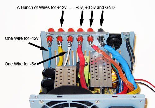
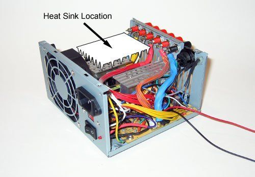
Set of wiresNow, the other difference you can see right away is that the ATX supply has a set of wires it comes with.
Some of the better units are modular, so you can just plug in the wiring looms you actually need, but typically, all of these are all permanently attached to the supply. On more powerful supplies, the wiring itself can take up as much space as the unit itself because it’s got enough plugs for 20 hard drives, four graphics cards, two mainboard and 12 floppy drives.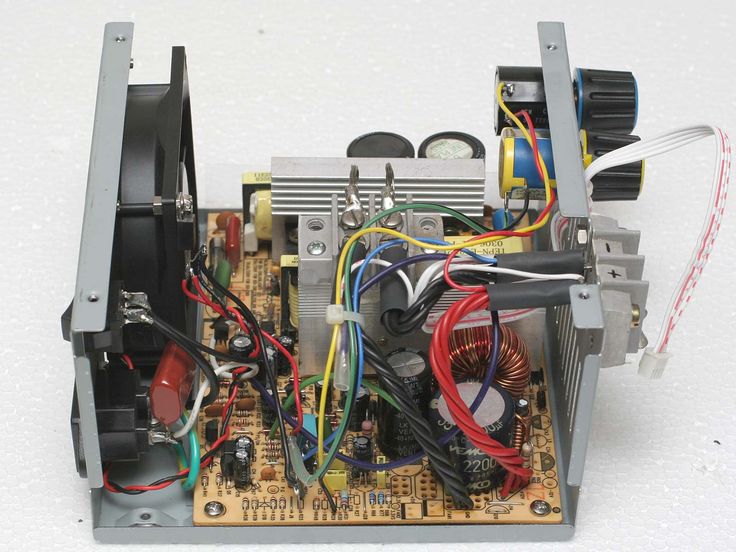 I always find it kind of heartbreaking to cut off the connectors from a perfectly good power supply, but the plugs on here really are only used in computer parts. Also, just one wire by itself can not handle the entire output power, so if you need more than 100 or 200W, you’ll have to splice together wires from different plugs, and that can get really messy.
More on that in a second, as there’s more to it, but one upside of having standard connectors is on the input side, where you’ve got the standard IEC receptacle, so at least on the mains, high voltage side, you have a really easy, clean and safe way to plug it in.
The industrial supplies just come with a bunch of screw clamps that you can tighten onto crimped connectors or bare wire, but not onto tinned wire, but that’s both for the AC mains input as well as the DC output, so you’ll have to hook up mains to it yourself, too. On the upside, each of these clamps on the output can basically carry the entire output current with a single wire as long as the wire itself can handle it.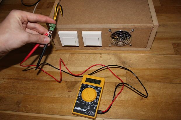
Ok, to expand on why you need to splice together wires on the ATX supply. The industrial supplies and also some simpler ATX units have just what’s called a single “rail”, basically one single output for 12V. But more more commonly on ATX supplies, there are two, three or four 12V rails, which are basically several independent supplies. One rail might supply the plug for the mainboard and power the CPU, another rail might be for one set of PCIe connectors for the graphics card and then another rail for the other set of PCIe connectors.
Now, it’s not entirely perfect just tying these separate supplies, these separate rails together, but it’s going to work to supply more current if you’re for example powering a large 12V heated bed. But to make use of the full output power, you will need to know which connectors are connected to which rails and grab power from each one, or just tie them all together.
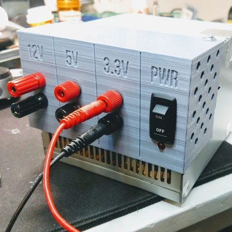
Group regulationAnd another thing that comes along with these supplies being built for computers is that they don’t just generate 12V, they also generate 5V, 3.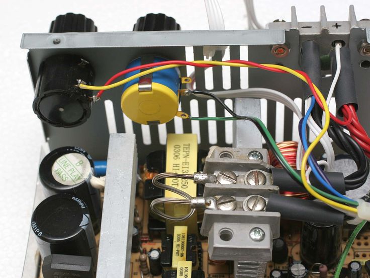 3V, -5V and -12V, those last two ones are often used for audio.
Now, on cheapers supplies, you’ll often find what’s called “group regulation”. In very simplified terms, these power supplies will regulate 12V, 5V and 3.3V together so that the voltages are just fixed ratios to one another, that simply saves cost because you only need one transformer that has multiple secondary windings. As we start drawing current from 12V, the voltage on 12V will slightly drop because we start having resistive losses inside the supply, so it will start trying to compensate for those losses by slightly increasing the voltage it’s trying to achieve, so that the actual output voltage will more or less stay constant, no matter if you draw 1A or 20A.
But with that group regulation, not only will the power supply compensate for that voltage drop on 12V, at the same time it will also increase the output voltage on 5V and 3.3V even though we aren’t drawing any current here. The safety mechanisms in the supply are still monitoring those two voltages, though, and if they go above the safe limit, it’s going to shut itself off.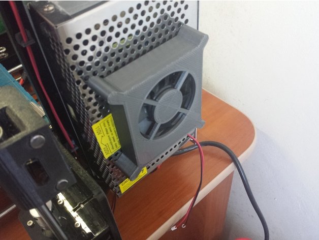
And that’s not uncommon to happen if you have a cheap supply and are drawing a good amount of load just from 12V, so one way to fix that, and that’s been done a lot, actually, is to just add a load to 5V and maybe 3.3V, all that needs to be is a resistor that wastes a few watts of power. I mean, I don’t think that’s very elegant, and I’ve not had to do it on any of my supplies yet, but then again, I don’t buy the very cheapest ATX supplies usually because I will probably use them in a PC at some point.
EfficiencyNext up, efficiency. If you’ve got cheap, subsidized, coal power, then you probably don’t care about a few extra watts that much, but when you’re paying 25 or 30ct per kWh, you probably do. Cheap industrial supplies will often claim “85-90% efficient”, which is hard to believe to say the least, typically they only manage about 70%. So if you have a printer that needs 100W to run, it will actually draw an extra 43W from the wall just for losses inside the power supply.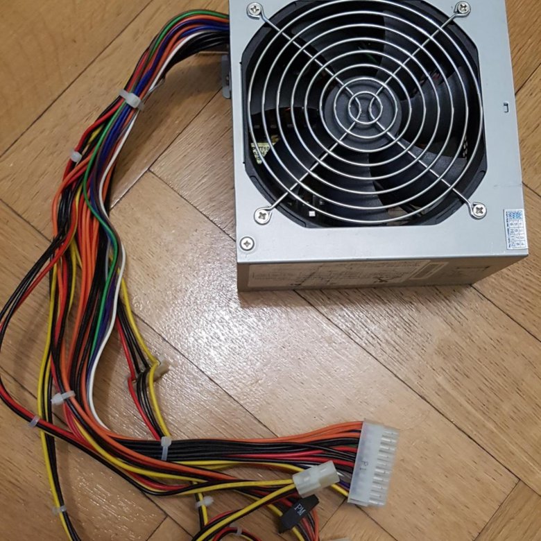
Brand-name industrial supplies are a lot better here, like the ones from Delta, Meanwell etc., but for ATX supplies, you have the “80+” certifications, which come in Standard, Bronze, Silver, Gold, Platinum and Titanium.
The higher you go up in level, the more efficient the supply will be across its entire load range, between 20% and 100% load. If a cheap supply only tells you one efficiency figure, that’s only for peak efficiency at one specific output load. Also, that achieve that better efficiency, 80+ supplies usually also use better components.
Switching on and offAnother upside of ATX supplies is the fact that you can switch them off. Not just with that switch on the back, which of course it super convenient, too, but by signaling through that green wire, you’ll no doubt have shoved a wire into the ATX connector before to turn it on or you’ll have seen these jumper plugs.
There are two incredibly cool things about this: First, we can control that signal with any 3D printer mainboard.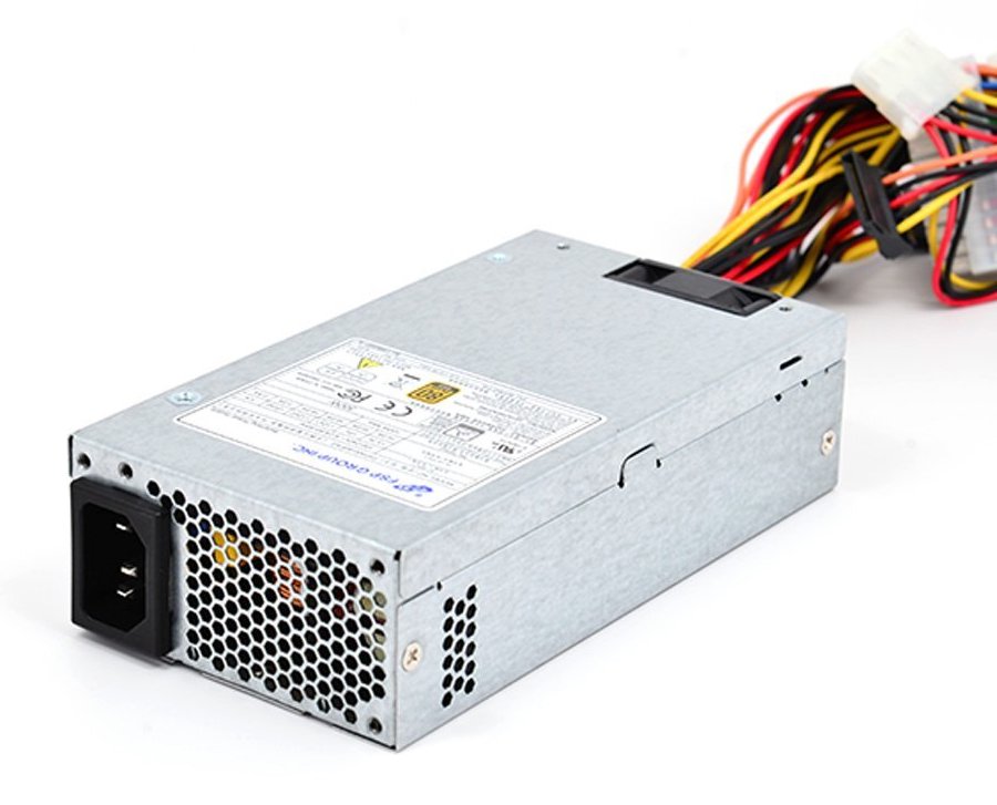 Marlin has support for switching on and off an ATX supply, it’s right there in the config, so with one gcode command, you can enable all the high-power parts on your printer that are connected to the 12V line from an ATX supply, and with another, you can turn them off again, and you can even use that as an emergency stop for example through OctoPrint. You can also use those gcodes in the start and end gcode, so that before and after a print, the printer turns itself on and off automatically, that saves some standby power and reduces the risk of anything dramatic going wrong when the printer is just sitting idle.
But the cool thing with that is that an ATX supply always provides 5V power for your electronics, even when you’ve switched it off electronically through the green wire.
The 5V_SB line provides enough current for at least a printer control board, and in many cases also enough for a Raspberry Pi so that you don’t need a separate power supply for that.
5V_SB is intended for keeping some functions enabled in a computer when it’s off, like wake on LAN, and more recently also to allow charging through the USB ports.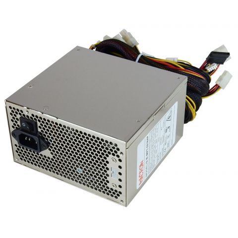 Check your power supply for the exact current rating.
So ATX supplies actually sound pretty cool so far, right? Well, there are two more things that are fairly strong arguments against using them. The first one is voltages. Now, printers have been moving to 24V because it’s easier to handle powerful heated beds with it as you’re reducing the current that’s needed to get the same output power, but it also gives stepper drivers more headroom to breath and actually improves the performance for higher movement speeds and fast accelerations in many cases. But of course, ATX supplies are only available with their main output voltage at 12V, while you can get these industrial ones in 5V, 12V, 24V, 36V, or 48V. Now, you or a printer manufacturers can work around that by for example carefully selecting the stepper motor and driver to work well at 12V, that’s totally doable, and move to a mains-powered heated bed. But then, of course once you do that, you don’t even need a power supply as capable as an ATX unit anymore, you can get away with one of these small brick-type supplies.
And the other factor, of course, is price. These industrial units have become incredibly cheap, spurred by an LED strip craze a few years ago and 3D printers coming up around the same time, so I just did a quick search for how much these are, shipped from Germany, taxes included;
A 12V 20A supply is 14€, a 30A unit is 16€, and a 24V, 10A unit, the same rating as in the MK3 is also 16€.
That is just incredibly hard to beat. Now of course, that’s the bargain bin quality units, so if you go for one of those, you should always buy one that’s rated for at least 30% more than you think you’ll need, and also, they will age over the years and lose some of their ampacity as the capacitors dry out, but the same exact thing also applies to super cheap ATX supplies. Now, with those you have to factor in that connectors are actually surprisingly expensive, even if you buy them in bulk, which is why modular supplies are so much more expensive than regular ones.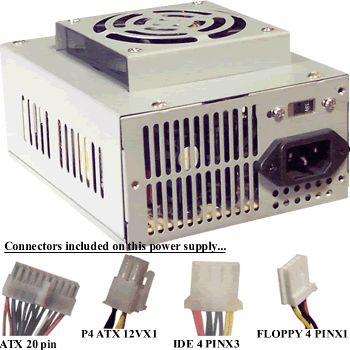
So you can get a “500W” unit, rated for 26A, so more like 300W, of which you should maybe use like 220W, for 16€, plus shipping this time, you can get a “600W” unit with two 20A rails, for around 22€, and then as we get into actually decent, brand-name, 80+ certified units, they start around 32€, 35€ for between 24 or 30A of output on 12V. Plus shipping.
Now, honestly, that’s still not super expensive, but you can also get an industrial Meanwell power supply at 12V and 20A, or 24V and 10A for about 40 bucks. Honestly, if you’re building a printer, you’re ok with a 12V system, want a decent supply and maybe are thinking about using that 5V standby line, which I think is a really neat feature, then an ATX supply is still a really good choice.
But when it comes to manufacturers, not only are they probably getting even better deals on industrial supplies in bulk, but for them, a smaller packaging size is also worth a lot as it saves on logistics, and dealing with ATX connectors also adds cost and complexity because they’ll need to have some solution to plug all relevant cables in, which means making a custom PCB or another wire harness, spending money on connectors again and also spending more time during assembly.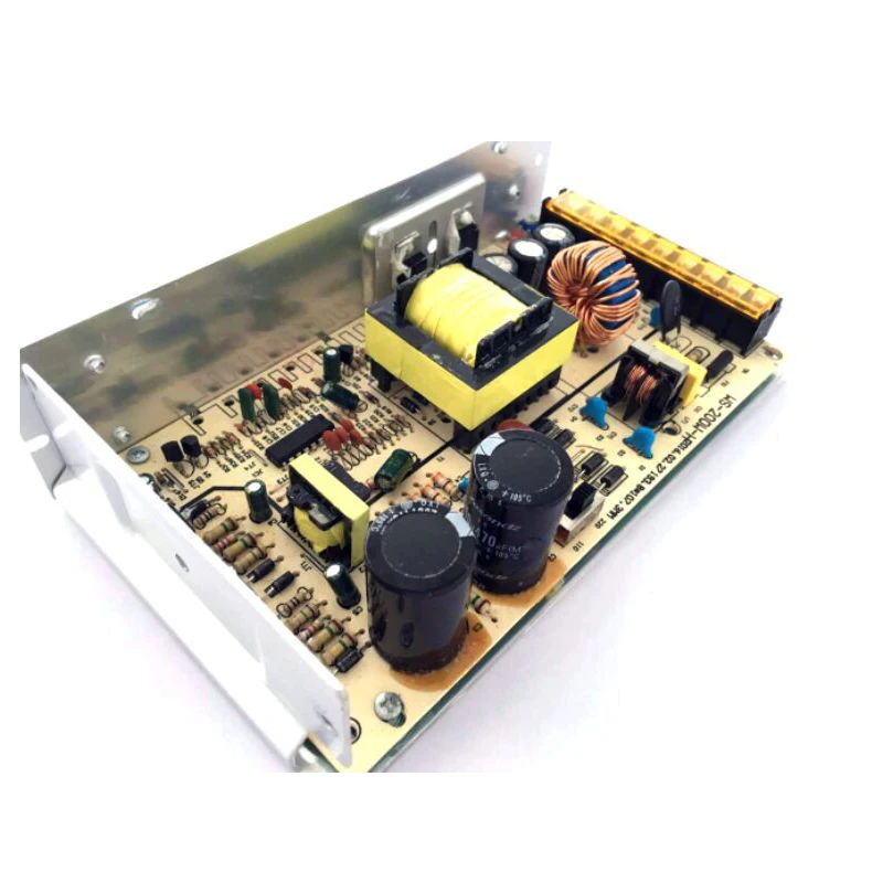 For them, I think it just makes a lot more sense to use the industrial supplies.
So if you’ve built a printer or customized one, let me know what you’ve used! Is the option for 24V the deciding factor? Maybe you’re also using an ATX supply with a boost converter just for the stepper drivers? Would totally make sense!
Get 24V 10A supplies
All my video gear
💙 Enjoying the videos? Support my work on Patreon!
Product links are affiliate links – I may earn a commission on qualifying purchases (at no extra cost to you)
Check out my second channel “More Layers” on YouTube for livestreams
SKR V1.3 ATX PSU - Take control of your printers power
Learn how to turn your 3D printer on and off again in Marlin 2.0 with the SKR V1.3 and an ATX PSU. Follow our guide and get to grips with PS_ON.
Being able to turn on and off the ATX PSU via the SKR V1.3 is a very handy function. Especially when it comes to that extra bit of safety. Moreover, the ability for the printer to self shutdown completely on receiving a thermal runaway is priceless.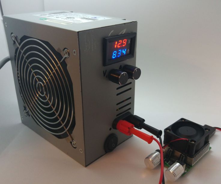
Parts List
Wires Cutters, Wire Strippers, 2.54mm JST-SM Connectors, 2.54mm JST-XHP Connectors, 16 AWG Silicone Cable.
ATX Breakout, while not necessary it does makes life a lot easier.
Affiliate links below:
Wiring the Relay
There are two ways we can set up the PS_ON switch, firstly as an emergency shut down, and kill all power. Secondly would be to have it shut down the main power and only leave 5 volts standby power remaining. Consequentially enabling the SKR V1.3 to still be available for firmware updates.
First, to make this easier to follow along I have broken it down into sections. However you will need the parts in the above list.
ATX to Relay
STEP 1
The first step is to make up some cable with the 26 AWG Silicone wiring. We will require two lengths red and black, that will reach from your ATX PSU to the point you have placed your relay.
Advertisement
The wiring needs to have Dupont connectors on one end and bare wire on the other.
- Connect the red wire Dupont’s connector to the pin on the Relay marked VCC and screw the other end into the ATX breakout board marked +5VSB.
- Similarly, the black wire the Dupont connector goes into the pin marked GND on the Relay board.
Now at this point the relay now gets power from the ATX PSU, but no switch method, and it goes to nowhere.
STEP 2
For the second step again we need some 26 AWG silicone cable. Requiring two lengths of black and green, long enough to reach from your ATX PSU, to the point you have placed your relay.
The both wires need to be bare wire on each end.
- Connect one end of the black wire into a spare COM terminal whilst the other end screws into the exit side of the relay marked NC (Normally Closed).
- The green wire can now be screwed into the PS_ON terminal on the ATX breakout board. While the green wire screws into the pin marked COM on the relay board.
Now at this point in time, the relay now gets power from the ATX PSU.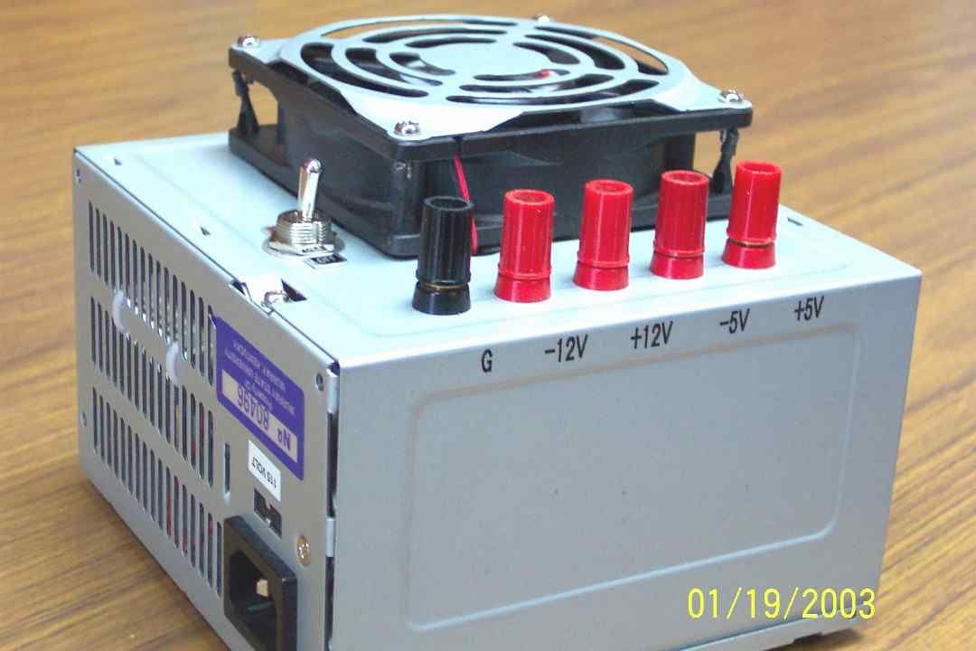 However it still has no switch method. Except now when activated the PS_ON will short with the GND, turning on the ATX PSU.
Advertisement
SKR V1.3 to Relay
STEP 1
This time around we only need one length of 26 AWG silicone cable in green. It must be long enough to reach from your SKR V1.3 to the relay board.
The wiring needs to have an 2.54mm JST-XHP on one end and a Dupont connector on the other.
- With the green wire attach the JST-XHP end to the signal on the Max_X switch, and the Dupont end to IN1 on the relay board.
Now at this point the relay now gets power from the ATX PSU. It now has a switch method, that will now activate the ATX PSU by shortening PS_ON will GND.
If you was just after a complete kill switch and not a method to be able to control the power supply, then please skip STEP 2 and move on into Configuring Marlin
STEP 2
But wait there is one more cable to go, if you require the ability to control your PSU and not just have a kill switch, this last wire is important.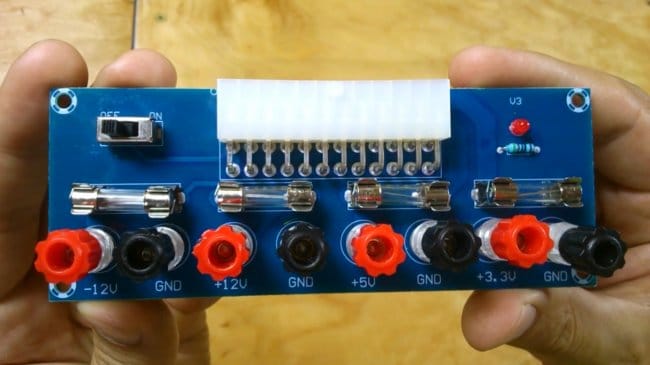
Final cable needs to be a red 26 AWG silicone cable, that again will reach the from the SKR V1.3 to the relay board.
The wiring needs to have an JST-XHP connector on one end and a bare wire on the other.
Advertisement
- With the red wire attach the JST-XHP end to the voltage on the Max_X switch, and the bare end to go into the +5VSB on the ATX PSU.
Now at this point the relay now gets power from the ATX PSU. It has a switch method, that will now activate the ATX PSU by shortening PS_ON will GND. Plus when the ATX PSU is turned off the printer will remain in standby mode (+5VSB).
Whilst in standby we can still configure the SKR V1.3 as if via USB power setup. Power to everywhere else including 12 Volts, 5 Volts and 3.3 Volts from the ATX will be shut off apart from the 5 Volts from the +5VSB.
Complete Wiring SchematicConfiguring Marlin 2 for PS_ON with SKR V1.3
Nearly done, a few quick changes in Marlin and we are finished.
Configuration.
 h
h#define POWER_SUPPLY 2 //Yes the xbox one //#define PS_DEFAULT_OFF // Personal choice if you want it off at startup
pins_BIGTREE_SKR_V1.3.h
Double check within the pins_BIGTREE_SKR_V1.3.h file that the below snippet of code, is included and activated. Remember to change the pin number if required.
#if POWER_SUPPLY > 0 #define SERVO3_PIN -1 #undef PS_ON_PIN #define PS_ON_PIN P1_28 #endif
Compile the firmware and upload, effects should be straight away.
Thats it, hopefully the SKR V1.3 ATX PSU guide was useful to you.
If you find our articles helpful and would like to help support the Make ‘N’ Print website, please visit the support us page for more information.
Advertisement
Alternatively, please have a look at our affiliate links in the 3D Printing Deals and Coupons section.
Thank You
PSU ATX for printer
I have long wanted to join the ranks of 3D printer users, and now this moment has come.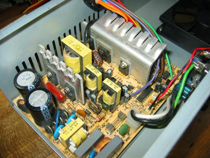
I will not describe the agony of justifying why I need it, choosing a type / model, waiting and assembling, because this is not what I would like to convey.
And I wanted to tell you how the third pancake turns out lumpy because of a thought that was postponed for later, as not significant.
And once again I am convinced that the power of any system requires special attention.
Details under the cut
So. The printer is based on a set of plastic parts Micromake D1. The rest was collected from different parts: something from Aliexpress, a profile from Chelyabinsk, hardware from the local hardware market.
And the main character of the post - PSU Power Master 250W from computer trash. The PSU was working, I didn’t even have to almost repair it (replaced electrolytes and eliminated the squeak of the duty room). Threw out the extra wires and connected.
The table will be heated, but the silicone heater is not connected yet, so I'm trying to print PLA on a cold table.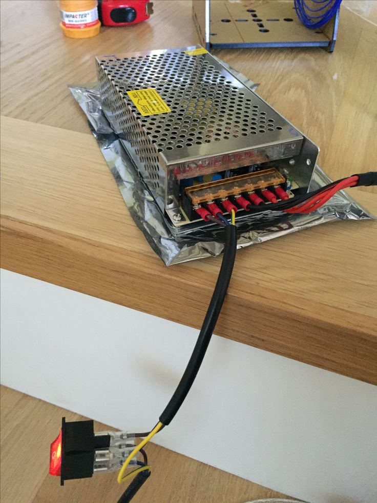
The first pancake turned out lumpy due to poor adhesion to the mirror table. I didn’t even degrease it, I just wiped it with a dry paper towel, as I was in a hurry to see the first result :D. Naturally, the model was torn off, but, to my surprise, on the second layer (although understandable).
The second attempt was already more thoughtful. Masking tape and the first finished model in 30 minutes showed off in my hands.
'The old man cast a net for the third time' ©
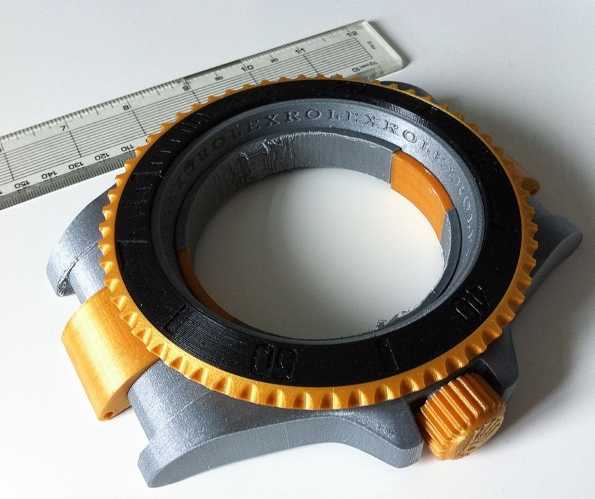
The third time I turned on the printer after 3 days (work, family...). A colleague asked me to print a mold for casting a silicone gasket. The model is small, estimated at 100 minutes. Why not continue to explore a new toy. I come home from work, start printing and sit down to dinner.
The first sign of the problem was that the extruder could not reach the set temperature of 200 gr. Literally 1-2 degrees were missing, and therefore printing did not start. Weird. I remembered that on that significant day of the first printing there were some exercises with heating and the temperature during printing was 1. 5-2 degrees below the set one. Although the calibration of the PID controller was carried out. Maybe that's how it should be? Okay, let's push. Made manual heating up to 205 and started printing. Alright, let's continue eating.
The second swallow already showed itself with a strange clicking after a couple of minutes. Now the bar feeder gear was slipping. Since it is inconvenient to diagnose with a fork in hand, I postponed it to 'after dinner'.
After dinner, the mood was even more clouded by the sight of a torn out bowden fitting from the feeder. Apparently he pushed the bar so actively that the plastic could not stand it. Repaired, loosened the clamp of the bar to the roller and began to search for the problem.
It turned out that after the start of printing, the extruder starts to freeze. Those. the temperature during printing begins to decrease and when it reaches the critical temperature, the bar freezes in the nozzle and the plastic supply is blocked. What I just didn’t do: re-calibration and raised the operating temperature - nothing helped - the temperature slowly, but fell.
After a couple of hours of ordeal, composing the correct Google query, I remembered that at the dawn of the PSU selection, I thought about the voltage stabilization mechanism. That in the ATX PSU, it is produced mainly on the 5-volt shoulder, which is not used in this case. Those. the load on the 12 volt circuit is practically not monitored. But at that moment I decided to postpone the solution of this problem. Moreover, this did not prevent the printing of the first model at all.
And remembering this, I decided to pay attention to the feeder and look at it, so to speak, with an armed eye.
The multimeter confirmed my fears. When the heating is on, the voltage drops from 12 to 11.5-11.3V, and when the engines start, it drops by another volt, that is, up to 10.5-10.7V. O_o!!! That's why the PID does not work.
Scheme on the monitor, soldering iron in hand. The FA-5-2 circuit is almost standard for the TL494 (for stabilization circuits). I will not give the whole scheme, it is easily searched on the Internet. I will bring the area subjected to violence.
20 kOhm is slightly higher than calculated for 12V and gives 13V. I was too lazy to look for another resistor, besides, I thought that this was not a big problem.
After such an alteration, the voltage stability has changed by an order of magnitude and the drawdown does not exceed 0.5V under maximum load. As a result, the temperature regime of the extruder has completely changed. The dynamics of its heating has clearly improved. Naturally, the PID controller has been calibrated.
So why didn't the first two attempts reveal nutritional problems?
The answer was revealed while contemplating my wife wrapped in a blanket. On the weekend, when I made the first tests, the CHPP spoiled us with hot batteries and it was relatively warm in the apartment. And on that ill-fated evening (or vice versa, the right one), the frost intensified a little and the wind rose, but the thermal power plant did not react. As a result, the temperature in the apartment dropped. Not much, but it was enough for the heater to no longer be able to bring the extruder to the desired temperature.
So those who plan to use computer power supplies as a PSU - be vigilant and double-check how its output voltage reacts to the load.
sorry for the many letters.
Health to all.
Power supply - online presentation
Similar presentations:
3D printing and 3D printer
Video card. Types of video cards
Apple analysis
Current and voltage transformers
Transistors
LG washing machine device. Electrical
Switchgear designs. (Lecture 15)
Electrical safety. Rules for the technical operation of electrical installations
Magnetic starters and contactors
Work on HF and VHF radio stations. Antennas of military radio stations. (Subject 5.1)
1. Power supply
Power supplyDefinition
Computer power supply (PSU) - power supply,
designed to supply computer nodes
with DC electricity by
converting the mains voltage to the required values.
To some extent, the
power supply unit also performs
stabilization and protection functions
against minor supply voltage interference.
As a component that
occupies a significant part inside
of the computer case,
carries in its composition the cooling components
of the parts inside
of the computer case.
Form factor
Power supply
ATX
TFX
Power supply
Power
Maximum output power
power supply. The most important parameter
, the more powerful the
power supply,
the more powerful
x
components can be installed in
our computer.
Power supply
Power
The power factor is the ratio of the power going
for useful work to the received. With active PFC
, the power factor reaches values from 0.95 to 0.99.
Performance (efficiency) - Efficiency
(ratio of output power to consumed). The higher
this value, the higher the efficiency of the power supply unit
and the less power loss.
Certification:
The 80 PLUS
certification of the power supply means that it meets certain
energy efficiency guidelines. For
80 PLUS certification, efficiency must be at least 80% at 20%, 50%, and 100%
load, relative to the rated power of the power supply.
Power Supply
80 PLUS Certification
Power Supply
Motherboard and
CPU Power
All modern
power supplies have
24 pin motherboard power. Depending on version
of the ATX12V standard, the power supply of the
processor can have either one
4 pin connector or two
connectors (4 pin + 4 pin) located on the
one power line. Connector 8 pin
specification EPS12V
additional power supply. If the power supply does not have special
connectors, then you have to use 2xPeripheral (Molex)
to 6pin adapters. The use of these adapters takes up
Peripheral (Molex) connectors, which may limit the installation of other
peripherals (hard drives, optical drives,
cooling devices).

Power supply
Connectors
Peripheral
(Molex)
Power supply for
video cards
More powerful versions of video cards can have 2 types of connectors
power supply: 6-pin and 8-pin, or both.
The 6-pin connector provides the
graphics card with an additional 75W of power, while the 8-pin connector provides 150W.
Thus, the maximum power consumption of a
video card with 1 8-pin connector and 1 6-pin connector can
reach the value: 75+150+75 = 300W (
connector configurations may differ, including upwards).
Connectors
Peripheral
(Molex)
Power supply for
graphics cards
Power supply
Power connector type
provided by him
Power
PCIE X16
75 W
6-PIN
75 W
8-PIN
150 W
SIGNITY
(MOLEX)
PERIPHERAL
power supply
1. AMP 171822- to supply 5 and 12 volts
to a peripheral device (usually an FDD drive).
2. Regular size Molex (molex 8981).