Tronxy 3d printer instructions
TRONXY XY-3 INSTRUCTIONS MANUAL Pdf Download
DownloadAdd to my manuals
Bookmark this page Manual will be automatically added to "My Manuals" Print this pageTable Of Contents
3-
page of 21
- Contents Table of Contents
- Bookmarks
Advertisement
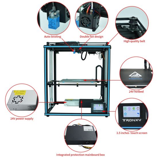
Model name:XY-3
Instructions
SHENZHEN TRONXY TECHNOLOGE CO. ,LTD
Table of Contents
Previous Page
Next Page
Related Manuals for TRONXY XY-3
- 3D Printers TRONXY XY-2 Instructions Manual
(13 pages)
- 3D Printers TRONXY XY-2 PRO User's Manual & Installation Manual
(20 pages)
- 3D Printers TRONXY XY-2 PRO User Manual
(20 pages)
- 3D Printers TRONXY X1 Assembly Manual
(27 pages)
- 3D Printers TRONXY X3A Assembly Manual
(30 pages)
- 3D Printers TRONXY X3A Instructions Manual
(22 pages)
- 3D Printers TRONXY X5SA-400-PRO User Manual
(33 pages)
- 3D Printers TRONXY X6-2E Instructions Manual
(25 pages)
- 3D Printers TRONXY X5 Assembly Manual
(16 pages)
- 3D Printers TRONXY X5SA-500-PRO User Manual
(32 pages)
- 3D Printers TRONXY X5SA-500 Installation Instructions Manual
(27 pages)
- 3D Printers TRONXY X5S Manual
(16 pages)
- 3D Printers TRONXY X5S 2E Manual
(25 pages)
- 3D Printers TRONXY X5SA Installation Instructions Manual
(24 pages)
- 3D Printers TRONXY X5SA-500-2E User Manual
(32 pages)
- 3D Printers TRONXY P802M Installation Manual
(29 pages)
Summary of Contents for TRONXY XY-3
TronXY X5S Build Guide
This is a build guide and review for the awesome (and large) TronXY X5S I purchased from banggood. com, but it is also available on gearbest.com.
Review
The build quality of this huge printer is reasonable given the price. The frame, heated bed and motors are all great. Electronics are based on the Arduino compatible Sanguino ATmega1284P processor. Drivers are the standard A4988. Electronics quality is reasonable and I've updated the config for Marlin 1.1.6, see the Firmware Update section on how to install this firmware update.
The layout is curiously similar to the Anet A8 control board.
You'll definitely want to change the hot end to an all metal version, since max working time of the PTFE lined extruder is a wimpy 260°C. The large metal case around the hot end makes it extremely hard to service on a jam or clog. The default part cooling fan is weak, but it's better than no fan at all.
Moreover, when printing at a reasonable 2800mm/min, I noticed that even PLA has trouble extruding, I believe this is due to the hot end having trouble holding its temperature. My fix for now is printing PLA at 210 degrees.
I plan to use a Titan-style extruder and pancake stepper motor, which is both lightweight and direct drive, with a Volcano heater block. My hope is to be able to do 100mm/sec with direct drive on PETG filament.
Unfortunately, the only UI element on the printer, the knob, is sticky for me... so definitely check this when installing the acrylic piece onto the LCD panel. Sand the acrylic hole bigger if necessary.
Unboxing
Packaging looks good. No damage on arrival.
Hardware
It even comes with a cute little PLA sample
and some tools
Be warned, the side cutters are DANGEROUS! They are cheap and will likely break off in your face! Don't risk using them. Just throw them away
Build
I'll walk through the whole build including some details and corrections to the manual. If you want to check out the manual, here is a copy: https://www.dropbox.com/s/wi54xz2ijhnyv9n/Tronxy_X5S.pdf?dl=1.
Lay out all the slotted beams.
Frame
You'll want to use the 4 double-thickness beams (they'll be vertical) along with the 2 single thickness beams with only 2 holes and 2 single thickness beams with 4 holes.
The shorter beams with 4 holes run parallel to the thicker side of the vertical beams... like this:
Find these bits of hardware:
8x 5mm x 25mm bolt 4x 4mm x 8mm bolt 4x T-nuts 4x 4mm washer 4x rubber foot
I used blue thread lock to make sure any movement from the machine will not loosen the bolts.
I assembled the longer ends first
Be sure to insert the T-nuts into the ends of the shorter beams before bolting down
Attach the rubber feet by screwing the small bolt through the washer and rubber foot into the T-nut
Find 8 more 5mm x 25mm bolts, the y-axis carriage mounts and attach.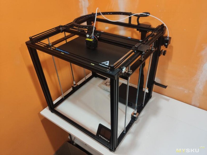 My mounts were different than the manual and erroneously both labeled "R". It's cool though, just mount them like this:
Measure diagonally across both the top and bottom to true up the cuboid that will soon be your printer
Tighten down the screws in the corners once everything is square
X and Y Carriage
Find the hot end, the last slotted aluminum bar and 4x 4mm x 8mm bolts.
Before installing the hot end and carriage onto the rail, check that the hot end is properly assembled. Mine was not Dan has a great guide about this on his blog. This article boils down to the fact that we want to make sure there is no gap between the throat and the nozzle. The following photo is from his blog.
This would be a good time to change the cooling block. If you have another printer, I suggest printing this cooling system and installing it now: https://www.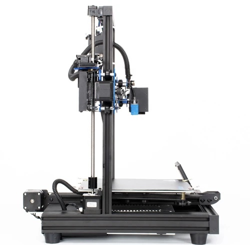 thingiverse.com/thing:2706922. You'll also need this adapter plate, if the included flan is a blower type: https://www.thingiverse.com/thing:2765424. The standardshroud will work OK as well, but is much less convenient, as the metal case covers the entire hot end. So, you can print one once you get your first printer set up!
You can be fairly certain that if your nozzle is screwed all the way into the heating block (no visible threads on the brass nozzle) that there is a gap. Notice this photo, there is no gap between the nozzle and heater, so probably a gap between the throat and the nozzle.
You'll want to unscrew the nozzle and screw the throat down into the heating block a bit more.
With the nozzle removed, I put the PTFE tube down into the throat, all the way to the heating block, then marked it with a sharpie, so I know how far the PTFE tube should be inserted when properly installed (the end of the PTFE should meet the brass nozzle).
Install the nozzle, tighten, then be sure to tighten again after heating up to ~240 degrees (once the printer is assembled).
Now, on with the assembly.
Install the carriage while ensuring not to over-tighten any parts that attach to acrylic, which could crack the part. Also, avoid letting any thread lock tough the acrylic, which will make the acrylic much more brittle.
X and Y Motors
Assemble the X and Y motor carriers using 3mm x 8mm screws and the t-Nuts
Affix these to the frame with 4 T-nuts and 4mm x 10mm. The overhanging bit of acrylic goes towards the center. One way to use the T-nuts is to put them on the bolts and then insert the whole assembly and tighten. The T-nuts will rotate into place.
Ps. this is how the T-nuts do that cool trick where they rotate into place but not further (notice how 2 corners are rounded):
Install the pulleys on the opposing corners using 6x 3mm x 10mm bolts and 6x T-nuts
It'll look like this when you're done
Z-Carriage
Next let's assemble the z-carriage
Use 12x 3mm x 8mm bolts to attach the 2 linear bearings and 1 guide nut to the two carriage ends
These extra holes are for the end stop screw and should be orientation towards the outside of the printer.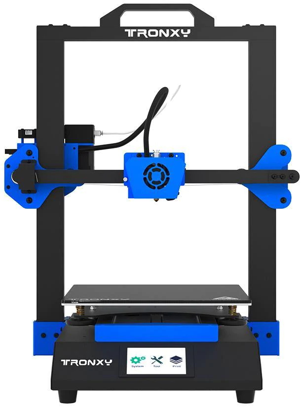 You'll see in some photos I've done this the wrong way, so I had to go back and put them on the outside
Here they are assembled
Prep the bearings with 4mm x 8mm bolts and T-nuts
Prep the z-axis motors using 4mm x 8mm bolts and T-nuts as well.
Loosely install the z-axis motors
Tighten both couplers to the motors using the set screws. I like to make sure they're as close to the same height (using calipers) as possible for easier measurement from top of the coupler to the bed later. This helps when leveling the printer.
Now insert the threaded rod, and two linear rods into the carriage and slip the bearing holder over the top. Install with 4x 4mm x 20mm bolts into the linear rods. I tightened the two on the bottom first then gently snugged up the top two bolts.
Slide the bearing holder up and snug up both the T-nut bolts and the set screws on the bearing holder and the motor coupler.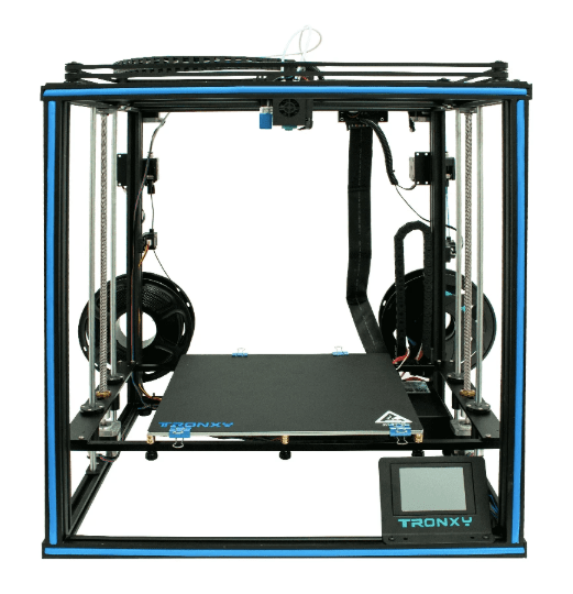
Install the extruder motor with two 4mm x 8mm bolts and T-nuts
Bed assembly
Here is the hardware you'll need:
8x 4mm x 12mm bolts to attach the assembly to the z-axis carriages on either side 6x 3mm x 30mm bolts 6x 3mm nuts 6x springs 6x wingnuts 6x lock washers (or thread lock)
And for later, the only 3d printed part in the kit, for the cable chain adapter. This attaches with 2x 3mm x 10mm bolts
Find the heated bed and remove the protective film
Using thread lock or the lock washers, attach each 30mm bolt to the heated bed. I highly suggest using a screw driver and pliers to make sure these nuts are very tight. It will make it much easer to work with later if these bolts cannot move.
Install the springs then the bars and wing nuts
Install the cable chain guide
And finally, install the bed
Tighten the wing nuts down so there is 8mm between the bed and the frame. 8mm is what the manual suggests, but this seems somewhat arbitrary. Adjust as you see fit.
Next I used 4x 3mm x 20mm bolts and the 8.5mm standoffs to install the LED screen. Make sure the knob spins freely in the hole in the acrylic. Mine is too tight, they should have cut it a few mm bigger, but it's fine, I'll take it apart and sand the hole bigger. Inserting the bolts and spacers all at once is super tricky using a pair of tweezers to insert the spacers one at a time might be easier.
Using 3x 4mm x 8mm bolts and 3 T-nuts, install the LED panel into the frame. It would be nice if this were angled.
My power supply came with the acrylic case installed, so I just installed it with 3x 4mm x 8mm bolts and T-nuts. Be sure to check the voltage switch is correct for your mains power.
Find the spool holder and install with 2 4mm x 10mm bolts and T-nuts. Use two pliers or wrenches to tighten this down so your spool doesn't come loose mid-print
Using 4x 3mm x 10mm bolts and 4x 3mm nuts, install the z-axis cable chain
Same for the y-axis carriage.
Install the end stops onto the end stop bracket like so
Install the last wingnut on the longest M3 screw and then insert it into the threaded hole on the z-carriage. Mount the end stop bracket
You should also have an acrylic sheet and some sort of print-bed surface in the box. I attached the plastic surface, which has an adhesive back, to the acrylic
Belts
Now lets install the belts & PTFE tube. The PTFE tube will just press into the fittings. To get an end out, press the plastic tab on the fitting down and pull up on the PTFE tube.
Notice here how the belt is zip tied to the extruder as well
Here is the reference diagram from corexy.com. Note that in our layout, the corner pulleys are stacked vertically, so the belts will not cross.
Loosen T-nut screws on the X and Y motors so they can slide forward, this way, you can slide them back later if you need more belt tension.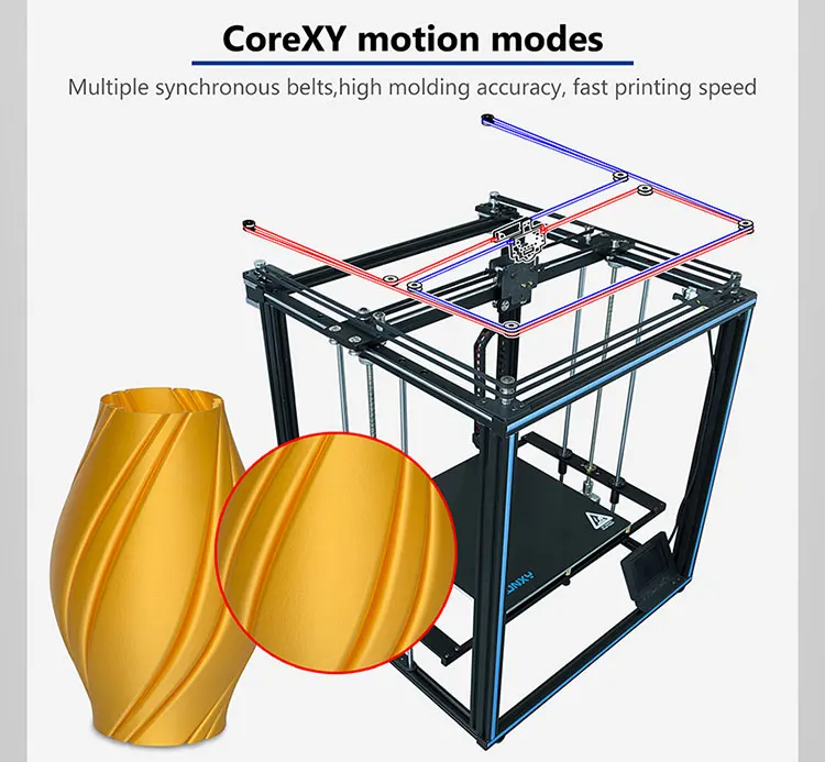
Install one belt at a time. One belt goes on the low set of pulleys and the other will go on the high set of pulleys. Here's the low set. It doesn't matter which belt uses the low or high set, as long as the belts don't cross, they won't rub.
A single belt attaches to opposite corners of the end effector carriage. Slide the belt on the carriage to the appropriate height, matching the pulley.
Here, all belts are installed and zip-tied down. Tension should be reasonably tight, but more importantly, the tension should be even.
Tighten the gears on the X and Y axis motors as well as tighten the motors into place using the T-nuts and bolts
Wiring
Here's the wiring diagram from the manual
I started by trying to wire everything before putting it in the case, since you won't be able to get to the screws on the top of the green screw terminals, once the case is installed. This turned out to be a huge mess.
Instead, I suggest you drill some holes in the top acrylic piece (the one with the fan on it) right over the screw terminals, so you can get to them after installing the board in the case.
Now install the case and mount the case onto the printer
Connect the LCD cables. The top cables goes to the right-most slot in this picture. No problem if you get these backwards though, just turn off the printer and switch them (you'll notice the screen lights up but has no text, in which case, just switch the cables)
Connect the end stops (X, Y then Z)
Then connect the white thermistor cables (e.g. temperature sensors), extruder then bed
Finally, install all the servo motor cables. The 6 pin sides go into the motors. Note the different length and labels.
Firmware Update
I've merged thingiverse user cyberbask's changes from google drive back into Marlin and made a few updates, like fixing the LCD, setting the correct extruder motor calibration settings and increasing the WATCH_TEMP_PERIOD to avoid the 'heating failed' messages.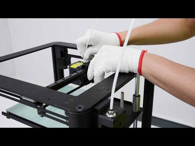
Download the code from here (click "Clone or Download" then "Download Zip") https://github.com/nathantsoi/Marlin/tree/tronxy-x5s-1.1.6
Per irrelevantxy on thingiverse, here is how you install Marlin 1.1.6:
Followed your instruction and successfully updated to Marlin 1.1.6 Just want to say THANKS! Below is the English instructions for those who need it. Download and install Arduino IDE 1.8.x Install Sanguino In preferences add this URL for additional board manager: https://raw.githubusercontent.com/Lauszus/Sanguino/master/package_lauszus_sanguino_index.json Go to the Board Manager and install the Sanguino. Select Sanguino and select the atmega1284 16mhz. Select the port where the printer appears Install u8glib for OLED Display Go to the libraries and install the u8glib Change upload speed Go to the Arduino Preferences and at the bottom find link to more preference in the directory for "preferences.txt" Click the link to folder, browse to \packages\Sanguino\hardware\avr\1.0.2\boards.txt Change the line to following: sanguino.menu.cpu.atmega1284p.upload.speed=57600 Restart the Arduino IDE (Important) *4. Change language setting Change the language setting in configuration file to "En" (English) Compile and upload the firmware
More on the firmware update here: https://www.thingiverse.com/groups/tronxy-x5s/forums/general/topic:25267
Extruder Calibration
If you're not using my firmware from above, this is the one thing you'll want to do to calibrate your printer, measure and set the amount of material extruded as follows to avoid under or over-extruding.
You'll notice there is a problem if there are gaps in your print or the walls look like they're oozing.
We'll tell the extruder to extrude a certain amount of filament and then compare it to the amount actually excluded.
Mark the filament 150mm above the top of the extruder.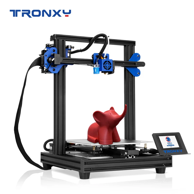
Run this command to extrude 100mm of filament at 90mm/min: G1E100F90
Now measure the mark on the filament to figure out how much was actually extruded.
Run M503 to see your current steps per mmm.
new steps per mm = (old_steps_mm) * 100 / extruded_length
Set it with M92E[new steps per mm value here] then run M500 to save.
Watch Tom's guide here https://youtu.be/YUPfBJz3I6Y
Tronxy X5SA-400, review and assembly of a Chinese monster)
For a long time I had the idea that very often I lack the standard 23*23*30 print sizes on my FDM printers. I looked at what is generally on sale, what can be collected at a relatively budget price. And the choice at the moment is not so great.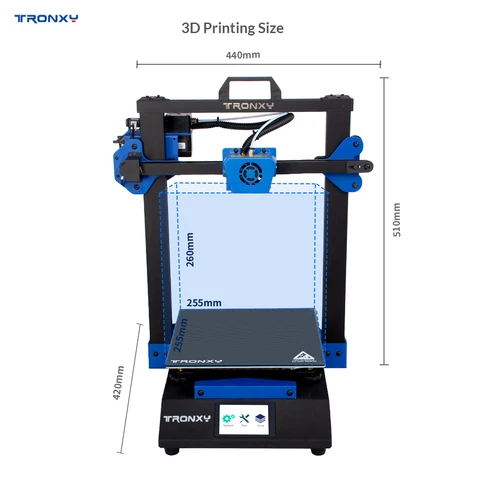 If you collect 30 * 30 there are few options. For example, the same ZAV, Z-bolt, etc., but I wanted even more, but the budget was not rubber. On Ali, if earlier there was a lot of choice, now everything is generally scarce. Mostly dry-tables like Aneta, Kreality and a couple of other options. nine0003
Drygostol really didn't want to take it. And I wished it was even bigger. And then he came to hand, Tronxy X5SA-400, print area 40 * 40 * 40. COREXY kinematics. A lot of things confused me about it, but this is practically the only option in this size, so the choice was made in favor of it.
Ordered from a warehouse in the Russian Federation, arrived very quickly, by courier to the door.
Such a weighty, large box. Despite the small bruises - everything was intact, everything was packed well inside. nine0003
Everything is laid out in sections, a heating table with insulation, a plate for better adhesion.
The plate surprised me. Usually it is just a sticker that is pasted on the table. But they decided to take it seriously. They stuck it on another piece of aluminum, and they suggest just staple it to the heating table.
At first I didn't quite get the ideas. But I found it to be a plus. The table is still not small, 40 * 40 after all. And an ordinary aluminum plate will sag more likely. The second plate on top will give a more even area. A monumental decision, I'm pleasantly surprised. nine0003
Under the second tier there is a profile, metal plates for fixing the table, hot end, power supply, board, etc.
When I took out the power supply-board, I saw how elegantly they invented to fix the screen. And it's a good decision. Damage during transportation is much more difficult.
And we get such a set for assembly. To admit it's a little unusual, all the parts take up sooooo much space. :)
There are many things that surprised me very pleasantly. For example Titan feeder. Well, this is a very good decision. In the photo in the seller's advertisement, an ordinary ancient MK8 was noted. And here is a pleasant surprise. nine0003
Almost all fasteners in the printer are metal, all carriages, brackets, etc. This is also very cool, it will give more rigidity. The only thing is the motor mounts - made of acrylic. With such a scale of metal mounts, leaving the motor mounts with acrylic is strange. Perhaps they did not figure out how to raise the motor to such a height with thin metal plates. But this is not critical, over time I will simply print new mounts and be calm. Acrylic is thick, I think it will last a long time. nine0003
Let's call the hotend and the entire airflow standard, now this solution is used on almost all printers. It works quite well on my other printers, for plastics like Pla-Petg-ABS it is quite excellent and hassle-free. Plus the auto level sensor comes from the factory. On small printers, I do without it, but here it will not be superfluous to use it.
And here is another "innovation" that I have not seen before. These nuts are eccentric nuts. This is already standard used by manufacturers to adjust the pressure of the wheels. But the new one is a cut-bevel, showing a landmark where the narrow part is. I was very happy about this. Usually I disassemble this mount, smear this edge with a marker and assemble it back. During assembly and especially during subsequent operation, you can immediately see where you need to turn a little to increase the pressure. For example, after a year, when the wheels get used, you will need to adjust a little. nine0003
Standard power supply, 24V, 360W.
The profile is cut evenly, all holes are marked well, everything is symmetrical. The table mounts are also metal.
The instruction is quite decent. Colored, detailed, the guys did their best. Assembled the printer on it, there were no surprises.
Well, now let's see what the fee is. Everything is on the tips, everything is crimped neatly. I really like how manufacturers are doing now. Take 2-3 years ago, everything was cobbled together in haste, just to sell. Little things in the form of tips and neatly laid out wires are a trifle that costs a penny, but the "product" looks much more serious. nine0003
They have their own fees. Your own cable to the screen and a cable to the hotend electronics. This is an interesting solution, wires minimum. Looks neat.
Drivers are TMS, that is, quiet. This was also a pleasant surprise, I did not expect. The only negative is that there are no heatsinks on the chips. And they heat up well and are quite demanding on cooling.
So I took heatsinks from 2208 drivers from my stock and glued them onto the chips. There is also a regular fan that will blow. Now I will be calm that everything will be fine. nine0003
Attention to detail is evident throughout the printer. Even the carriages are signed left-right.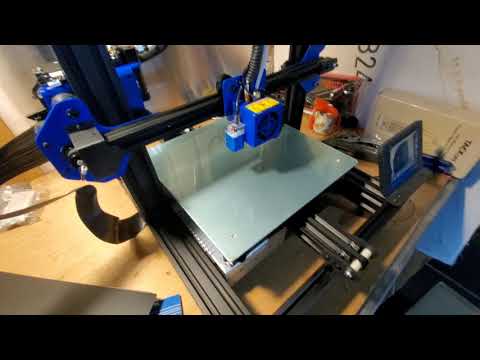 Usually you have to guess from the pictures in the instructions, but here it’s immediately clear.
I always bathe bearings of this kind in gasoline before installation, dry them and generously smear them with normal grease. For example Mobile blue. They might have been lubricated. My opinion is that such bearings use a lubricant rather than a transport lubricant. In any case, flushing and applying a good proven lubricant will only benefit. nine0003
So let's start collecting. Frame size is about 60*70*65. Looks monstrous. In the middle for comparison are the usual keys.
When assembling, sometimes I had to climb on a stool. :-D
And now let's get to what I was most worried about before buying. The photo clearly showed that the vertical profile is 4020, and the horizontal ones are 2020. On small printers, I use the same profile and everything is ok there. But here all the same sticks of 70 cm. And the wheels roll on them. I was worried that they would sag towards the middle. Let it be a little, but it's not great. And here I was once again surprised by the ingenuity of the manufacturer. They put the guide shafts in the middle of the profile, in the instructions they suggested using nuts to compensate for the thickness so that the shaft would fit tightly and twist with the profile. nine0003
Thus, we rested our profile and it will not sag anywhere. And this added rigidity. It's genius.
And this is a good old tradition. Offer to put "thrust bearings", clamping the lead screw from above. I don’t know who came up with this, and why many manufacturers continue to listen to “that person”. I suggest just tossing them out. You don't need to put them on.
So, our handsome man is assembled. To be honest, I'm very pleasantly surprised. I expected that everything would be bad, that I would be modifying it for a very long time, gaining stiffness, and so on. But no, I was very pleasantly surprised by this printer. nine0003
Oversized fasteners. This is all that is left after assembly.
Now the first step is to calibrate the table with the nuts. In the future, the autolevel sensor will build a "curvature map", but the table must be leveled initially. Everything is conveniently done on the menu. 5 points drive the printer and check the gap.
I always use this 0.05 mm automotive dipstick. It's very convenient for me to check them. nine0003
The nozzle was 0.4 from the factory. I put 0.5 right away. All the same, the printer was taken in order to print huge pieces.
Then I did what the manufacturer categorically forbids doing. The manufacturer warns - after flashing you fly off the warranty. This didn't scare me, so I sewed a fresh Marlin 2.0 into it. I do not like closed firmware. Plus, the standard firmware had rather low accelerations, it printed perfectly, but slowly. I needed speed first and foremost. Therefore, I raised the acceleration and typing speed. The firmware and how to flash it is easily searched in Google, I will not talk about it.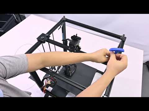 nine0003
And the first thing I did was print a standard test cube. The parameters used are coarse. 0.5 line width, 0.3 layer height. Travel speed 110, print speed 70. Petg plastic from Strimplast, nozzle temperature 235, table 80. The cube came out very worthy.
But the printer was not bought in order to print miniature cubes. Just received a large order. And immediately after printing the first cube, I decided to put it into combat conditions.
So, the first huge detail. Here I used the line width as 0.5, and set the layer height to 0.4. I filled up the flow of plastic more. Since it was necessary that the part was strong, but there was no time to test. We immediately went into battle.
Bubbles are just a consequence of the fact that I piled up the flow.
So, let's move on, the next detail, the flow is slightly reduced, the print is already prettier.
And here is the fourth detail, here I reduced the flow even more, and the result became more elegant. nine0003
Part black and white in half due to running out of white spools. The low filament sensor worked fine, then I put in a spool of black (the white ran out at that point) and continued printing. Everything worked perfectly.
I made the parts with a "groove" so that they fit together, and the joint will be more convenient to glue and fix easier.
And here is the result of printing out of the box. 5 days without turning off plowed perfectly without any failures. All printing defects (which were caused by my experiments with the flow) were easily removed by the grinder. nine0003
This "Wine Bottle" will decorate the photo zone of one of the restaurants in our city. It was handed over to the customer for further gluing, painting and making fasteners.
What can I say in the end - I'm more than happy with it.
It costs quite reasonable money. As practice has shown, it is very well thought out in terms of assembly and filling. The manufacturer did not save on "matches".
How to evaluate the printer and my satisfaction with it - I am saving up for one more printer, but the size is even larger). The manufacturer currently has models with a print area of 50*50*60 and 60*60*60. The choice of the next large printer I think is a foregone conclusion, it remains to decide on the size;)
a good choice for a beginner maker / 3D printers, machines and accessories / iXBT Live
A good 3D printer for beginners is an inexpensive and high-quality 3D printer with auto-calibration and useful functions (filament detector, print pause). The new model from TRONXY - the XY-2 printer with the “PRO” modification has not only this, but also an increased print size (up to 255 x 255 x 260 mm), as well as a powerful power supply that gives quick warm-up and start, and all this for modest price of $180. The mounted inductive sensor on the movable head ensures accurate multi-point calibration in automatic mode. The printer is already assembled and configured, so you do not have to rack your brains upon receipt. I will try to tell in general terms about the printer itself and the basic things at the first start of printing. nine0003
TRONXY XY-2 PRO 3D PRINTER
The newest Tronxy XY-2 Pro 3D printer is an improved version of the already popular 3D printer that can "just a little more". Print field 255 x 255 x 260 mm. The printer is all metal, has a rigid frame, inductive self-leveling sensor, huge (3.5") touch control display, filament sensor. Specially designed extruder allows printing with soft materials (for example, TPU). Current cost is $180 minus store coupon ($3 and promo codes) . nine0003
Features:
Brand: Tronxy
Model: XY-2 Pro
Print field 255 x 255 x 260 mm
Control: 3.5" touch screen
Calibration: automatic, inductive Z sensor
Options: filament sensor fast warm-up, print pause, automatic filament change
Power: 360W
Plastic type: PLA HIPS WOOD PC PVC ABS PETG 1. 75mm
75mm
Maximum working speed: 180mm/s
Nozzle diameter: 0.4mm
Positioning accuracy: 0.0125mm0185 Layer thickness: 0.1-0.4mm
The packaging of the printer is thoughtful and compact - the portal is laid in the foam, accessories are in layers, at the bottom there is a frame with electronics and a table.
Kit includes: assembled vertical gantry (completely, with X-axis and extruder), lower part (stand, table, Y-axis, power supply, display, control unit), bag with gouges and screws, tools, spatula, spare ends and hot end, power cord, detailed instructions and frame for the coil. Well, a trial spool of filament (PLA 330g). nine0003
I will immediately make a reservation about the features of the assembly.
First you need to dock the portal to the base part. Specifically, for this printer model, you must first rearrange the display, which is fixed in the transport position (hidden under the table).
| Carefully remove the display from under the table and move | .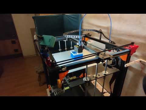 .. onto the front frame profile. Mounting in T-nuts in the groove .. onto the front frame profile. Mounting in T-nuts in the groove |
| Check that it does not touch the table when moving | Next, we prepare the portal for assembly (4 screws m6x30 mm) |
Holes are already pre-drilled and chamfered in the frame. We carefully try on everything and twist it. There is a tool in the kit, I personally use an electric screwdriver (quickly and conveniently). It makes sense to install the screws on the thread lock - this will eliminate loosening, but complicate reverse disassembly. So if you are not going to disassemble it, then you can use it.
This is what the assembled printer looks like. As you can see, it was already checked at the factory, the belts were tightened and set up.
The printable area is 255 x 255 (XY) and 260 mm (vertical). A fairly large size, 20 percent more than the usual Ender-3. The plastic used for the printer is common - you can see it here and here.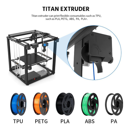
After installation, we check the electrics.
| Connect the engine connector Z | All connectors in the printer are marked (Z1 in the photo) |
| X-Axis Adapter Cable - The PRO version has a special adapter that simplifies connection | This method is much more convenient than the usual "spider". |
In the kit there is a special adhesive pad - it is better to calibrate with it.
| An inductive sensor | is mounted on the head. Screws for adjusting the tilt of the table are visible on the table |
| . The hot part is covered with a casing. | Carriages and brackets with metal rollers |
| The blower is located outside the casing: an impeller with a nozzle | There are stationery clips for fixing the lining.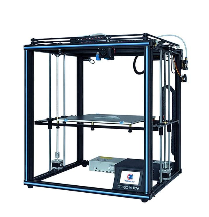 |
On the electronics unit, the manufacturer placed a sticker with information about the model and basic characteristics. There is also a QR code - a link to the official Tronxy group on FB.
The printer has a well-placed electronics and power supply.
| On the photo is the Y end, bracket with motor, bypass roller | Can be controlled via USB, or printed from MicroSD |
| Power is supplied through a standard socket, next to a fuse and a backlit toggle switch. | Extruder simple, plastic, modified for soft plastics |
| Coil is mounted on a bracket on the top bar | Screw on the top Z axis is clamped in the bearing. |
Tronxy printer ready to go.
In principle, it does not take up much space on the table. nine0003
Before starting work, you need to calibrate the level of the table at several points. It works automatically, there is a corresponding menu.
Alignment takes place using an inductive sensor. The head moves along the grid, lowers until the sensor is triggered, and deviations are calculated. When triggered, the red LED lights up.
Large touch screen. With the help of this, it is a pleasure to manage the printer. The menu contains the main functions. The screen starts with the display of 3 icons - settings (System), tools (Tools), printing (Print). nine0003
| At startup, select the desired menu. | In the Tools menu, manual movement, preparation, plastic loading, leveling, fan adjustment, emergency stop and Z level change (for example, when using additional glass) are available warning - check that nothing interferes with the table | 0210 | All three fans are controlled by software. Thermal barrier and model airflow in %, electronics airflow on/off only.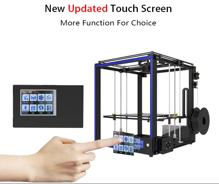 The printer can be made "quieter" The printer can be made "quieter" | The firmware version is fresh. Upgradeable from MicroSD |
| Printer Status Window - Position and Temperatures | Print menu "Print" | |||
| Select a file, start printing. There is a pause for changing the filament | A number of parameters can be adjusted when printing. | |||
The printer is ready to go. We fill the plastic - we press the extruder lever, we push the bar. If you are interested in how extruders differ and how they work, you can read the article about the BMG extruder. nine0003
Please note that there is a filament break (end) sensor in front of the extruder. The plastic is filled - the light is on.
Install the coil on the bracket.
Push the bar through the hot nozzle.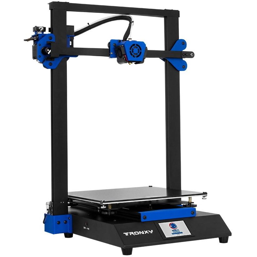 I have red PETG refilled, but you can see that they checked it with blue PLA at the factory.
Before the start, I check the operation of the heating elements - I check the heating of the table and nozzle with a thermal imager.
Slicers are standard, there are no tricks, there are profiles on the USB flash drive, examples of models for the test.
Print test)))
During printing, you can change the parameters on the fly - speed, temperature, etc.
Measures approx. 20 cm.
Battery case.
If you pause during printing, the automatic offers to change the color. So the printer allows you to print in layers in different colors. plus the printer. nine0003
The enlarged working area (255 x 255 mm) makes it possible to print also large parts. The photo shows a detail of a compound bow.
TRONXY XY-2 PRO 3D PRINTER
So, using the printer is easy and convenient. The basic things have already been implemented - the printer is assembled, configured, tested, the belts are tensioned.